US8995515B2 - Dynamically adjusted OFDM channel estimation filtering in OFDM communications - Google Patents
Dynamically adjusted OFDM channel estimation filtering in OFDM communications Download PDFInfo
- Publication number
- US8995515B2 US8995515B2 US13/339,321 US201113339321A US8995515B2 US 8995515 B2 US8995515 B2 US 8995515B2 US 201113339321 A US201113339321 A US 201113339321A US 8995515 B2 US8995515 B2 US 8995515B2
- Authority
- US
- United States
- Prior art keywords
- channel
- raw
- filtering
- channel estimate
- filter
- Prior art date
- Legal status (The legal status is an assumption and is not a legal conclusion. Google has not performed a legal analysis and makes no representation as to the accuracy of the status listed.)
- Active, expires
Links
- 238000004891 communication Methods 0.000 title claims abstract description 49
- 238000001914 filtration Methods 0.000 title claims description 58
- 238000000034 method Methods 0.000 claims abstract description 36
- 238000004590 computer program Methods 0.000 claims description 11
- 125000004122 cyclic group Chemical group 0.000 claims description 7
- 230000006872 improvement Effects 0.000 claims description 7
- 238000012935 Averaging Methods 0.000 claims description 6
- 239000000284 extract Substances 0.000 claims description 3
- 230000001174 ascending effect Effects 0.000 claims description 2
- 238000005259 measurement Methods 0.000 claims 3
- 230000001131 transforming effect Effects 0.000 claims 1
- 230000005540 biological transmission Effects 0.000 description 31
- 239000011159 matrix material Substances 0.000 description 13
- 239000013598 vector Substances 0.000 description 13
- 230000004044 response Effects 0.000 description 12
- 230000008569 process Effects 0.000 description 9
- 230000006870 function Effects 0.000 description 8
- 238000010586 diagram Methods 0.000 description 7
- 230000015654 memory Effects 0.000 description 7
- 238000005516 engineering process Methods 0.000 description 6
- 230000008901 benefit Effects 0.000 description 5
- 230000003287 optical effect Effects 0.000 description 4
- 238000012545 processing Methods 0.000 description 4
- 230000002596 correlated effect Effects 0.000 description 3
- 230000007774 longterm Effects 0.000 description 3
- 238000004364 calculation method Methods 0.000 description 2
- 230000000875 corresponding effect Effects 0.000 description 2
- 230000007423 decrease Effects 0.000 description 2
- 238000009499 grossing Methods 0.000 description 2
- 230000000644 propagated effect Effects 0.000 description 2
- 230000000717 retained effect Effects 0.000 description 2
- 238000013515 script Methods 0.000 description 2
- 230000003595 spectral effect Effects 0.000 description 2
- 239000002699 waste material Substances 0.000 description 2
- 238000013475 authorization Methods 0.000 description 1
- 238000004422 calculation algorithm Methods 0.000 description 1
- 230000003247 decreasing effect Effects 0.000 description 1
- 239000000203 mixture Substances 0.000 description 1
- 238000012986 modification Methods 0.000 description 1
- 230000004048 modification Effects 0.000 description 1
- 230000009467 reduction Effects 0.000 description 1
- 239000004065 semiconductor Substances 0.000 description 1
- 238000004088 simulation Methods 0.000 description 1
- 239000007787 solid Substances 0.000 description 1
- 230000003068 static effect Effects 0.000 description 1
- 239000000758 substrate Substances 0.000 description 1
- 238000012546 transfer Methods 0.000 description 1
Images


Classifications
-
- H—ELECTRICITY
- H04—ELECTRIC COMMUNICATION TECHNIQUE
- H04L—TRANSMISSION OF DIGITAL INFORMATION, e.g. TELEGRAPHIC COMMUNICATION
- H04L25/00—Baseband systems
- H04L25/02—Details ; arrangements for supplying electrical power along data transmission lines
- H04L25/0202—Channel estimation
- H04L25/0212—Channel estimation of impulse response
-
- H—ELECTRICITY
- H04—ELECTRIC COMMUNICATION TECHNIQUE
- H04L—TRANSMISSION OF DIGITAL INFORMATION, e.g. TELEGRAPHIC COMMUNICATION
- H04L25/00—Baseband systems
- H04L25/02—Details ; arrangements for supplying electrical power along data transmission lines
- H04L25/0202—Channel estimation
- H04L25/0224—Channel estimation using sounding signals
-
- H—ELECTRICITY
- H04—ELECTRIC COMMUNICATION TECHNIQUE
- H04L—TRANSMISSION OF DIGITAL INFORMATION, e.g. TELEGRAPHIC COMMUNICATION
- H04L27/00—Modulated-carrier systems
- H04L27/26—Systems using multi-frequency codes
- H04L27/2601—Multicarrier modulation systems
- H04L27/2647—Arrangements specific to the receiver only
Definitions
- This patent document relates to wireless communications, wireless communication devices and wireless communication systems.
- Wireless communication systems use electromagnetic waves to communicate with wireless communication devices located within cells of coverage areas of the systems.
- a radio spectral range or band designated or allocated for a wireless communication service or a particular class of wireless services may be divided into different radio carrier frequencies for generating different communication frequency channels.
- the communication capacity increases as the number of the communication frequency channels increases.
- Two different frequency channels, when placed too close to each other in frequency, can interfere or cross talk with each other to create noise and thus reduce the signal to noise ratio.
- One technique to reduce the minimum frequency spacing between two adjacent channels is to generate different channels within a given band by using the orthogonal frequency division multiplexing (OFDM). This technique generates channel spectral profiles that are orthogonal to one another without interference when different channels are centered at selected equally-spaced frequencies.
- OFDM orthogonal frequency division multiplexing
- the frequency spacing can be smaller than the minimum spacing in conventional frequency channels and hence increase the number of channels within a given band.
- IEEE 806.16x standards support wireless communications under OFDM and orthogonal frequency division multiple access (OFDMA).
- OFDM and OFDMA orthogonal frequency division multiple access
- a wireless communications method includes receiving a plurality of reference signals on a plurality of subcarriers, performing channel estimation to obtain a plurality of raw channel estimates based on the received plurality of reference signals, determining a number of raw channel estimates to be used for a channel estimate refinement and calculating a refined channel estimate using the number of raw channel estimates from the plurality of raw channel estimates.
- a communication system based on orthogonal frequency domain multiplexing can include a network of base stations that are spatially distributed in a service area to form a radio access network for wireless communication devices.
- Each base station includes a receiver module that receives a plurality of reference signals on a plurality of subcarriers; a channel estimation module that performs channel estimation to obtain a plurality of raw channel estimates based on the received plurality of reference signals; a channel estimation filter module that determines a number of raw channel estimates to be used for a channel estimate refinement; and a channel estimation refinement module that provides a refined channel estimate using the number of raw channel estimates from the plurality of raw channel estimates.
- OFDM orthogonal frequency domain multiplexing
- a wireless communications apparatus for performing channel estimation in an orthogonal frequency domain multiplexing (OFDM) communications system.
- the apparatus includes a receiver module for receiving a plurality of reference signals on a plurality of subcarriers, a channel estimation module for performing channel estimation to obtain a plurality of raw channel estimates based on the received plurality of reference signals, a channel estimation filter module for determining a number of raw channel estimates to be used for a channel estimate refinement and a channel estimation refinement module for calculating a refined channel estimate using the number of raw channel estimates from the plurality of raw channel estimates.
- OFDM orthogonal frequency domain multiplexing
- a computer program product comprising a non-volatile computer readable medium having computer executable instructions stored thereon.
- the instructions include code for facilitating receiving a plurality of reference signals on a plurality of subcarriers, performing channel estimation to obtain a plurality of raw channel estimates based on the received plurality of reference signals, determining a number of raw channel estimates to be used for a channel estimate refinement and calculating a refined channel estimate using the number of raw channel estimates from the plurality of raw channel estimates.
- FIG. 1 shows an example of a wireless communication system.
- FIG. 2 shows an example of a radio station architecture.
- FIG. 3 shows an example of a wireless communication system that may implement an OFDM receiver system in accordance with an embodiment.
- FIG. 4 is a diagram illustrating an exemplary OFDM receiver system.
- FIG. 5 is a graph illustrating exemplary SER as a function of data SNR and channel estimation SNR.
- FIG. 6 is a diagram illustrating an exemplary OFDM receiver system in accordance with an embodiment.
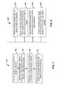
- FIG. 7 is a flowchart representation of a process of wireless communications.
- FIG. 8 is a block diagram representation of a portion of a wireless communication apparatus.
- FIG. 9 is a flowchart representation of a method of obtaining a channel estimate in a receiver.
- FIG. 10 is a flowchart representation of a method of allocating filtering resources in a receiver.
- OFDM receivers often require channel estimation as part of the process of decoding the signal that was transmitted.
- the transmitter is configured to periodically transmit a known reference signal (also known as a pilot signal) on certain subcarriers. By comparing the signal actually received to the signal known to have been transmitted, the receiver can estimate the response of the channel.
- a known reference signal also known as a pilot signal
- LTE OFDMA uplink it is often the case that the reference signal is configured to occupy several adjacent subcarriers. Because the channel response between adjacent subcarriers is highly correlated, the channel response from adjacent or nearby subcarriers can be combined and averaged so as to produce improved channel estimates. This is called channel estimate filtering in the frequency domain.
- LTE Long Term Evolution
- Filtering may be a computationally intensive operation, and in some cases, is not necessary if the signal to noise ratio of the channel estimates is acceptable without any filtering. Utilizing a static or fixed filtering algorithm may waste computational resources when its result would be to produce filtered channel estimates with a signal to noise ratio that exceeds the target performance requirement. In contrast, a dynamic channel estimate filter calculation, which varies filter length L as a function of the signal to noise ratios of the unfiltered and required filtered channel estimates, could better optimize computational resources and permit the receiver to perform channel estimate filtering on more channels at the same time.
- FIG. 1 illustrates an exemplary wireless communication system 100 that uses communication channels at different frequencies under OFDM or OFDMA to provide wireless communication services based in accordance with an embodiment.
- the system 100 may include a network of base stations (BSs) or base station transceivers (BSTs) 120 that are spatially distributed in a service area to form a radio access network for wireless subscribers or wireless subscriber stations (SSs) 110 .
- BSs base stations
- BSTs base station transceivers
- SSs wireless subscriber stations
- a base station 120 may be designed to have directional antennas and to produce two or more directional beams to further divide each cell into different sections.
- Base station controllers (BSCs) 130 are connected, usually with wires or cables, to BSs 120 and control the connected BSs 120 .
- Each BSC 130 is usually connected to and controls two or more designated BSs 120 .
- the wireless system 100 may include a carrier packet network 140 that may be connected to one or more public switched telephone networks (PSTN) 150 and one or more packet data networks 160 (e.g., an IP network).
- PSTN public switched telephone networks
- a mobile switching center (MSC) 152 may be used as an interface between the BSCs 130 and the PSTN 150 .
- MSC mobile switching center
- a packet data serving node 142 may be used to provide an interface between the carrier packet network 140 and the packet data network 160 .
- a carrier packet network manager 144 may be connected to the carrier packet network 140 to provide various network management functions, such as such as an AAA server for authentication, authorization, and accounting (AAA) functions.
- AAA authentication, authorization, and accounting
- Each subscriber station 110 may be a stationary or mobile wireless communication device. Examples of a stationary wireless device may include desktop computers and computer servers. Examples of a mobile wireless device may include mobile wireless phones, Personal Digital Assistants (PDAs), and mobile computers. A subscriber station 110 may be any communication device capable of wirelessly communicating with base stations 120 .
- the system in FIG. 1 may be applied to the communication bands from 2 to 11 GHz under OFDM and OFDMA provided in IEEE 802.16x standards such as IEEE 802.16d (January, 2004).
- OFDM and OFDMA systems the available frequency band is divided into subcarriers at different frequencies that are orthogonal.
- a subchannel is formed from a subset of subcarriers.
- OFDMA a total of 32 sub channels are allocated to each radio cell.
- a base station (BSs) or base station transceiver (BSTs) 120 may include an OFDM receiver.
- OFDM receivers may provide channel estimation as part of the process of decoding the signal that was transmitted.
- the transmitter is configured to periodically transmit a known reference signal (also known as a pilot signal) on certain subcarriers. By comparing the signal actually received to the signal known to have been transmitted, the receiver can estimate the response of the channel.
- a known reference signal also known as a pilot signal
- LTE OFDMA uplink it is often the case that the reference signal is configured to occupy several adjacent subcarriers. Because the channel response between adjacent subcarriers is highly correlated, the channel response from adjacent or nearby subcarriers can be combined and averaged so as to produce improved channel estimates. This is called channel estimate filtering in the frequency domain.
- LTE Long Term Evolution
- FIG. 2 shows a schematic diagram of an exemplary OFDM receiver which performs channel estimate filtering in the frequency domain.
- the exemplary processing shown in system 200 to generate filtered channel estimates may be performed using any combination of hardware and software suitable to implement functionality disclosed herein.
- the hardware may include a digital signal processor, such as a TMS320TCI6616 wireless base station system-on-a-chip from Texas Instruments Incorporated of Dallas, Tex.
- the digital signal processor may be configured with processor executable instructions.
- the processor executable instructions may be stored in random access memory (RAM) within or in communication with the digital signal processor, or non-volatile memory within or in communication with the digital signal processor, such as a read-only memory (ROM), EEPROM (Electrically Erasable and Programmable Read Only Memory), or E-flash (embedded flash).
- RAM random access memory
- ROM read-only memory
- EEPROM Electrically Erasable and Programmable Read Only Memory
- E-flash embedded flash
- the executable instructions that configure the digital signal processor may implement a number of software modules or applications that communicate with one another and with hardware and software inside and outside of base station, in order to implement the functions of an OFDM receiver 200 .
- the received baseband signal 202 is sent into a module 204 which removes the cyclic prefix (CP) from the OFDM symbol (CP removal module).
- the output of the CP removal module 204 is sent into the system DFT module 206 which transforms the signal from the time domain to the frequency domain.
- the signal then goes into a pilot compensation (PC) module 208 which extracts the subcarriers that were used to transmit the reference sequence and also compensates for the known reference signal that was transmitted.
- PC pilot compensation
- H raw ⁇ ( i ) D ⁇ ( i + P 1 ) P ⁇ ( i ) , 0 ⁇ i ⁇ N REF - 1 Equation ⁇ ⁇ ( 1 )
- H raw is the output of the PC module 208
- N REF is the number of the system DFT subcarriers that are actually occupied by reference symbols
- P 1 is the location of the first reference symbol in the output of the system DFT.
- P is a length N REF vector that contains the known reference symbols that were sent from the transmitter (it is assumed that no reference symbol has the value 0). For example, suppose it is known that the transmitter has transmitted 35 reference symbols (vector P) on subcarriers 123 through 157 . In this case, P 1 would be 123 and N REF would be 35 .
- H raw is a vector containing the raw channel estimates.
- H raw would perfectly represent the channel response between the transmitter and the receiver (H actual ).
- noise corrupts the channel estimates and filtering is often used to improve the accuracy of the channel estimates.
- the channel estimate filter (CEF) 210 module attempts to take advantage of the known a-priori auto-correlation properties of the channel response so as to produce refined channel estimates 212 with improved accuracy. Since the channel responses of nearby subcarriers are usually correlated, filtering can be applied so as to combine adjacent channel estimates to produce a final refined channel estimate vector called H filt .
- This filtering operation is often designed so that a filter of length (L) is applied to all of the channel estimates. It may or may not be the case that the same length L filter is applied to all channel estimates.
- M smooth [ c 0 , 0 c 0 , 1 c 0 , 2 c 0 , 3 c 0 , 4 0 0 0 0 0 0 c 1 , 0 c 1 , 1 c 1 , 2 c 1 , 3 c 1 , 4 0 0 0 0 0 0 0 c 2 , 0 c 2 , 1 c 2 , 2 c 2 , 3 c 2 , 4 0 0 0 0 0 0 0 0 c 3 , 0 c 3 , 1 c 3 , 2 c 3 , 3 c 3 , 4 0 0 0 0 0 0 0 0 c 4 , 0 c 4 , 1 c 4 , 2 c 4 , 3 c 4 , 4 0 0 0 0 0 0 0 0 c 4 , 1 c 4 , 2 c 4 ,
- the leftmost L entries of the upper (L+1)/2 rows and the rightmost L entries of the lower (L+1)/2 rows will contain coefficients.
- the coefficient locations of any particular row will be located in the same positions as the non-zero entries of the previous row, but shifted to the right by one position.
- the leftmost L entries of the upper L/2 rows and the rightmost L entries of the lower L/2+1 rows will contain coefficients.
- the coefficient locations of any particular row will be located in the same positions as the non-zero entries of the previous row, but shifted to the right by one position.
- Another manner is to first create the autocorrelation matrix of the channel, R H,L , of size L ⁇ L. Specifically,
- R H , L E ⁇ [ H actual ⁇ ( 0 : L - 1 ) ⁇ H actual H ⁇ ( 0 : L - 1 ) ] ⁇ s 2 Equation ⁇ ⁇ ( 4 )
- the notation A(a:b) indicates that only elements a through b of vector A are to be retained. All other elements are to be discarded
- ⁇ s 2 is the average received power of the channel
- the operator H represents the Hermitian operation.
- M ref,L,SNR ( R H ⁇ 1 +I*SNR ) ⁇ 1 SNR Equation (5) where ⁇ n 2 the average power of the noise introduced by the receiver.
- SNR is the signal to noise ratio or
- d a,b represent the coefficient in row a, column b of M ref,L,SNR
- c a,b d 2,b 2 ⁇ a ⁇ 9 0 ⁇ b ⁇ 4 Equation (7)
- c a,b d a-7,b 10 ⁇ a ⁇ 11 0 ⁇ b ⁇ 4 Equation (8)
- the upper (L+1)/2 rows of M ref,L,SNR are assigned to the upper (L+1)/2 rows of M smooth and the lower (L+1)/2 rows of M ref,L,SNR are assigned to the lower (L+1)/2 rows of M smooth .
- the intermediate rows are all assigned the coefficients of row (L+1)/2 ⁇ 1 of M ref,L,SNR .
- the upper L/2 rows of M ref,L,SNR are assigned to the upper L/2 rows of M smooth and the lower L/2 rows of M ref,L,SNR are assigned to the lower L/2 rows of M smooth .
- the intermediate rows are all assigned the coefficients of row L/2 ⁇ 1 of M ref,L,SNR.
- the larger the value of L the more filtering that is possible on the channel estimates and the more noise that can be eliminated from the channel estimates.
- every increase in L can lead to an increased implementation cost.
- FIG. 3 shows an example of the tradeoff between channel estimation signal to noise ratio (SNR) and data SNR of a particular receiver.
- SNR channel estimation signal to noise ratio
- Different receivers will have different curves and hence the traces 300 in FIG. 3 are presented only as examples.
- different receivers will have different performance targets.
- one receiver's performance target may be a symbol error rate (SER) of 10%. SER rates better (smaller) than 10% do not result in increased performance for the receiver.
- Another receiver's performance target may be a particular block error rate (BLER). Performance better than the target BLER may not result in a system with increased overall performance.
- SER symbol error rate
- BLER block error rate
- the channel estimation SNR SNR CE,required
- SNR CE,raw 5 dB
- Receivers are usually designed to handle the worst case, which, for the current example, is a 5 dB SNR CE,raw and SNR DATA . If SNR CE,raw and SNR DATA were, for example, 4 dB, no amount of channel estimate filtering could ever produce an SER better than 10 ⁇ 1 .
- the filter length, L would be chosen such that even if SNR CE,raw and SNR DATA were 5 dB, the channel estimates would be improved to 11 dB such that reception would be possible.
- filtering resources are wasted. For example, if the SNR CE,raw and SNR DATA were 7 dB, the same length L filter would be applied to the channel estimates thereby improving the SNR of the channel estimates to some value better than 7 dB, perhaps even as much as 12 dB. However, by examining the dotted trace in the figure, one sees that actually, if SNR DATA is 7 dB, the SNR required on the smoothened channel estimates (SNR CE,required ) so as to achieve a 10 ⁇ 1 SER is also 7 dB. Thus, actually, in this case, there is no need to perform any channel estimate filtering at all. Thus, filtering channel estimates would waste resources and would not result in an overall increase in performance.
- FIG. 4 is a diagram illustrating an exemplary OFDM receiver system 400 in accordance with an embodiment.
- the received baseband signal 202 is sent into a module 204 which removes the cyclic prefix (CP) from the OFDM symbol.
- the output of this module 204 is sent into the system DFT 206 which transforms the signal from the time domain to the frequency domain.
- CP cyclic prefix
- the signal then goes into a pilot compensation (PC) module 208 which extracts the subcarriers that were used to transmit the reference sequence and also compensates for the known reference signal that was transmitted.
- PC pilot compensation
- H raw is the output of the PC module 208 .
- N REF is the number of the system DFT subcarriers that are actually occupied by reference symbols.
- P 1 is the location of the first reference symbol in the output of the system DFT 206 .
- P is a length N REF vector that contains the known reference symbols that were sent from the transmitter (it is assumed that no reference symbol has the value 0). For example, suppose it is known that the transmitter has transmitted 35 reference symbols (vector P) on subcarriers 123 through 157 . In this case, P 1 would be 123 and N REF would be 35 .
- H raw is a vector containing the raw channel estimates.
- H raw would perfectly represent the channel response between the transmitter and the receiver (H actual ).
- noise corrupts the channel estimates and filtering is often used to improve the accuracy of the channel estimates.
- the system 400 operates by first estimating the received signal power ⁇ circumflex over ( ⁇ ) ⁇ s 2 and the received noise power ⁇ circumflex over ( ⁇ ) ⁇ n 2 .
- Several techniques are available to estimate the noise power.
- One technique is to take advantage of transmission gaps from the transmitter. If the transmitter stops transmitting for even one OFDM symbol, the signal going through the receiver is composed completely of noise. Hence, the receiver can estimate the total received power during the transmission gap which, in this case, would be equal to the received noise power.
- the receiver may be pre-calibrated and hence the receiver noise power may be known in advance.
- the total received noise may even be a function of temperature and this function may also be known in advance.
- the received signal power can be estimated is by using estimates of the received noise power. If the total noise power has already been estimated, the receiver can then estimate the total received power (including both noise and signal). The received signal power can be extracted by subtracting the received noise power estimate from the received total power estimate.
- the filtered channel estimates from a different transmission from the same transmitter can be used to estimate the received signal power during the previous transmission from that transmitter. If it can be assumed that the current transmission will be received with a signal power similar to the signal power used during the previous transmission, then the previous received signal power can be used as an estimate of the received signal power for the current transmission.
- the system 400 may construct various filters 602 that will be used to smooth the raw channel estimates as to produce refined channel estimates 604 with improved accuracy.
- these filters may be represented as matrices.
- the system 400 may be able to construct the matrix M L,S which is the matrix to be used to filter the channel estimates when the SNR is equal to S.
- L represents the number of multiplications used per filtered channel estimate.
- the M L,S matrix may have the form shown in the equation below. In other words, each row may have at most L non-zero coefficients arranged in a mostly diagonal pattern, as shown below.
- coefficient locations of any particular row may be located in the same positions as the non-zero entries of the previous row, but shifted to the right by one position.
- the leftmost L entries of the upper L/2 rows and the rightmost L entries of the lower L/2+1 rows may contain coefficients.
- the coefficient locations of any particular row may be located in the same positions as the non-zero entries of the previous row, but shifted to the right by one position.
- Another manner is to first create the autocorrelation matrix of the channel, R H,L , of size L ⁇ L. Specifically,
- R H , L E ⁇ [ H actual ⁇ ( 0 : L - 1 ) ⁇ H actual H ⁇ ( 0 : L - 1 ) ] ⁇ s 2 Equation ⁇ ⁇ ( 11 ) where the notation A(a:b) indicates that only elements a through b of vector A are to be retained. All other elements are to be discarded. ⁇ s 2 is the average received power of the channel.
- M ref,L,SNR ( R H ⁇ 1 +I*SNR ) ⁇ 1 SNR Equation (12) where ⁇ n 2 is the average power of the noise introduced by the receiver. SNR is the signal to noise ratio or
- c a,b d a,b 0 ⁇ a ⁇ 1 0 ⁇ b ⁇ 4 Equation (13)
- c a,b d 2,b 2 ⁇ a ⁇ 9 0 ⁇ b ⁇ 4 Equation (14)
- c a,b d a-7,b 10 ⁇ a ⁇ 11 0 ⁇ b ⁇ 4 Equation (15)
- the upper (L+1)/2 rows of M ref,L,SNR are assigned to the upper (L+1)/2 rows of M smooth and the lower (L+1)/2 rows of M ref,L,SNR are assigned to the lower (L+1)/2 rows of M smooth .
- the intermediate rows are all assigned the coefficients of row (L+1)/2 ⁇ 1 of M ref,L,SNR .
- the upper L/2 rows of M ref,L,SNR are assigned to the upper L/2 rows of M smooth and the lower L/2 rows of M ref,L,SNR are assigned to the lower L/2 rows of M smooth .
- the intermediate rows are all assigned the coefficients of row L/2 ⁇ 1 of M ref,L,SNR.
- the system 200 may determine how much of a channel estimation SNR improvement may be produced by that particular matrix. This is represented by the variable G L,S .
- G L,S For example, for M 5,10 dB it may be that G 5,10 dB is equal to 5 dB. This means that if raw channel estimates are received with an SNR CE,raw of 10 dB and these channel estimates are filtered using 5 coefficients per filtered channel estimate according to matrix M 5,10 dB , the SNR of the channel estimates after filtering (SNR CE,smooth ) is improved by 5 dB. In this case, the channel estimates has a SNR CE,smooth of 15 dB.
- G L,S constants may be calculated through the use of simulations. However, these constants may be monotonically non-decreasing in the parameter L as long as S is held constant. That is, for a particular received SNR value, as L is increased and more and more raw channel estimates are combined to produce a filtered channel estimate, the filtered channel estimate may have better and better noise properties. It is also expected, however, that the benefits of increasing L may decrease as L becomes bigger and bigger. For example, if L changes from 1 to 4, it is expected that G L,S may increase much more than if L changes from 11 to 14.
- the receiver knows the modulation that is used, the coding rate that is used, the number of subcarriers that are used, and the offset between the power of the reference symbols and the power of the data.
- the receiver can generate plots similar to those in FIG. 5 .
- one plot can be created that relates SNR CE,raw and SNR DATA to some required system performance metric.
- the plots in FIG. 5 indicate the SER for a particular combination of SNR CE,raw and SNR DATA for a particular configuration of the key transmission parameters.
- Different systems have different performance metrics. For example, some systems may have a performance metric measured as the BLER. In most communications systems, there is a minimum performance requirement and there is no need for the system to perform better than this minimum requirement.
- the system 400 may examine the performance data, such as plots, and determine the SNR CE,required that satisfies the performance requirements of the receiver.
- the system 400 may then compare the SNR CE,required with the SNR CE,raw If SNR CE,raw exceeds SNR CE,required , there is nothing to be done and no channel estimate filtering is performed. In this case, even without performing any filtering on the channel estimates, the receiver can meet the performance target.
- the system 200 may then examine the G L,S curve and attempt to find the minimum value of L such that the SNR after filtering (SNR CE,smooth ) is sufficient to satisfy the performance requirements of the receiver.
- SNR CE,raw is so low that no amount of filtering will allow the receiver to properly receive the signal.
- the best strategy may be to simply give up and not even bother attempting to demodulate the data.
- the system 400 may only use resources as necessary to filter the channel estimates. In cases where the received signal has a high SNR, this system 400 uses relatively few resources to demodulate the transmitted data. As the SNR decreases, the system 400 uses progressively more and more resources to demodulate the data, but never more resources than are necessary. This is a clear improvement over a receiver that always filters the channel estimates with a fixed length filter. Such a receiver would often perform more filtering than was absolutely necessary, thereby wasting resources.
- Another embodiment is applicable when multiple transmitters share the same OFDM link with a single receiver.
- the transmitters are usually separated in the frequency domain where different transmitters are scheduled to transmit on different subcarriers.
- this embodiment first treats each transmitter independently according to the previous embodiment. For example, if 3 transmitters T 1 , T 2 , and T 3 are being received during a particular OFDM symbol, the optimal matrix M L,S is chosen for each transmitter based on the previously described embodiment. This results in three matrices M L 1 ,S 1 , M L 2 ,S 2 , and M L 3 ,S 3 to be used to smooth the channel estimates received from each transmitter.
- L 1 , L 2 , and L 3 may have different values.
- An OFDM receiver may often have a fixed amount of resources dedicated to channel estimation filtering for all transmitters for each OFDM symbol. It may be that during a particular OFDM symbol, the number of resources available are sufficient to perform filtering with all 3 matrices.
- a resource scheduler can be used to decide how many resources to allocate to the smoothing of the channel estimates for each transmitter.
- one strategy may be to reduce the L values of all the transmitters thereby reducing the total amount of resources required to filter all the estimates from all the transmitters. For example, one can reduce the L values by 10% (while still making sure that no L value goes below 1), and see if enough resources are available to filter the channel estimates with the new L values. If not, the L values can be reduced by another 10% to see if the resource requirements have been sufficiently reduced. This process can continue until the resource requirements have been reduced to the point that the available resources would be sufficient.
- the drawback with the above resource scheduling strategy is that by reducing the L values, the performance metric of all the transmissions may drop below the minimum performance requirement of the receiver. For example, if a set of L values has been chosen so as to result in a 10% SER for all transmitters, any reduction in L values may result in all transmitters having a performance worse than 10% SER.
- An alternative strategy is to simply drop one of the transmissions. If the available resources are not sufficient to allow every transmission to have an adequate performance metric, then, one can simply discard one of the transmissions. In this situation, the discarded transmission may not be received but the remaining transmissions may all be able to satisfy the minimum performance requirement of the receiver.
- One strategy is to drop the transmission with the smallest resource requirements. Transmissions may be dropped continuously until the required amount of resources is lower than the available amount of resources.
- a priority can be assigned to each transmission. For example, emergency transmissions can be assigned a high priority and other types of transmissions can be assigned lower priorities. The lowest priority transmissions may be dropped first. Transmissions may be dropped continuously until the required amount of resources is lower than the available amount of resources.
- FIG. 5 shows an example of a wireless communication system.
- a wireless communication system can include one or more base stations (BSs) 505 a , 505 b , one or more wireless devices 510 and an access network 525 .
- a base stations 505 can provide wireless service to wireless devices 510 in one or more wireless sectors.
- a base station 505 a , 505 b includes directional antennas to produce two or more directional beams to provide wireless coverage in different sectors.
- the access network 525 can communicate with one or more base stations 505 , 505 b .
- the access network 525 includes one or more base stations 505 , 505 b .
- the access network 525 is in communication with a core network (not shown in FIG. 5 ) that provides connectivity with other wireless communication systems and wired communication systems.
- the core network may include one or more service subscription databases to store information related to the subscribed wireless devices 510 .
- a first base station 505 can provide wireless service based on a first radio access technology, whereas a second base station 505 can provide wireless service based on a second radio access technology.
- the base stations 505 may be co-located or may be separately installed in the field according to the deployment scenario.
- the access network 525 can support multiple different radio access technologies.
- wireless communication systems and access networks that can implement the present techniques and systems include, among others, wireless communication systems based Code Division Multiple Access (CDMA) such as CDMA2000 1x, High Rate Packet Data (HRPD), evolved HRPD (eHRPD), Universal Mobile Telecommunications System (UMTS), Universal Terrestrial Radio Access Network (UTRAN), Evolved UTRAN (E-UTRAN), Long-Term Evolution (LTE), and Worldwide Interoperability for Microwave Access (WiMAX).
- a wireless communication system can include multiple networks using different wireless technologies.
- a dual-mode or multi-mode wireless device includes two or more wireless technologies that could be used to connect to different wireless networks.
- a wireless device can support Simultaneous Voice-Data Operation (SV-DO).
- SV-DO Simultaneous Voice-Data Operation
- FIG. 6 is a block diagram representation of a portion of a radio station 605 .
- a radio station 605 such as a base station or a wireless device can include processor electronics 610 such as a microprocessor that implements one or more of the wireless techniques presented in this document.
- the radio station 605 can include transceiver electronics 615 to send and/or receive wireless signals over one or more communication interfaces such as antenna 620 .
- the radio station 605 can include other communication interfaces for transmitting and receiving data.
- Radio station 605 can include one or more memories configured to store information such as data and/or instructions.
- the processor electronics 610 can include at least a portion of the transceiver electronics 615 .
- FIG. 7 is a flow chart representation of a wireless communications process 700 .
- the process may be implemented in an OFDM receiver, such as a UE or a base station.
- a plurality of reference signals is received on a plurality of subcarriers.
- channel estimation is performed to obtain a plurality of raw channel estimates, based on the received plurality of reference signals.
- a number of raw channel estimates to be used for channel estimate refinement is determined.
- a refined channel estimate is calculated using the number of raw channel estimates from the plurality of raw channel estimates.
- the operation of determining the number of raw channel estimates includes determining the number using an SNR criterion.
- a priori calculations are performed to establish a relation between the number of raw channel estimates and an SNR improvement that can be obtained when that number of raw channel estimates are used in the refinement operation.
- the number of raw channel estimates are filtered (e.g., using a linear averaging filter) to obtain refined channel estimates.
- FIG. 8 is a block diagram representation of a portion of a wireless communications apparatus 800 .
- the module 802 e.g., a receiver module
- the module 804 e.g., a channel estimation module
- the module 806 is for determining a number of raw channel estimates to be used for a channel estimate refinement.
- the module 808 e.g., a channel estimation refinement module
- the apparatus 800 and modules 802 , 804 , 806 and 808 may further be configured to implement one or more techniques discussed in this patent document.
- FIG. 9 is a flow chart representation of a method 900 of obtaining a channel estimate in a receiver.
- a baseband signal having a cycle prefix and corresponding to a channel is received.
- the cyclic prefix is removed from the baseband signal.
- the baseband signal is transformed from a time domain to a frequency domain to yield a baseband signal in the frequency domain.
- a subcarrier used to transmit the baseband signal is extracted from the baseband signal in the frequency domain to yield a raw channel estimate.
- a required signal to noise ratio for a filtered channel estimate is determined.
- a minimum number of filter multiplications per raw channel estimate is determined, which is required to achieve a required signal to noise ratio for the filtered channel estimate.
- the minimum number of multiplications per filtered channel corresponds to a determined filter length.
- the raw channel estimate is filtered with a filter of the determined filter length to yield the filtered channel estimate.
- FIG. 10 is a flow chart representation of a method 1000 of allocating filtering resources in a receiver.
- a required signal to noise ratio for a filtered channel estimate corresponding to the channel is determined.
- a minimum number of filter multiplications per raw channel estimate is determined, which is required to achieve a required signal to noise ratio for the filtered channel estimate, wherein the minimum number of multiplications per filtered channel corresponds to a determined filter length.
- available filtering resources of a receiver are allocated in an ascending order of determined filter lengths required for each channel.
- the raw channel estimate is filtered with a filter of the determined filter length to yield the filtered channel estimate.
- the number of subcarrier raw channel estimates, that may be used to calculate a refined channel estimate is determined using operations conditions such as signal and noise powers.
- raw channel estimates obtained in the frequency band of each individual subcarrier may be linearly combined (e.g., averaging) to obtain a refined channel estimate.
- the disclosed and other embodiments, modules and the functional operations described in this document can be implemented in digital electronic circuitry, or in computer software, firmware, or hardware, including the structures disclosed in this document and their structural equivalents, or in combinations of one or more of them.
- the disclosed and other embodiments can be implemented as one or more computer program products, i.e., one or more modules of computer program instructions encoded on a computer readable medium for execution by, or to control the operation of, data processing apparatus.
- the computer readable medium can be a machine-readable storage device, a machine-readable storage substrate, a memory device, a composition of matter effecting a machine-readable propagated signal, or a combination of one or more them.
- data processing apparatus encompasses all apparatus, devices, and machines for processing data, including by way of example a programmable processor, a computer, or multiple processors or computers.
- the apparatus can include, in addition to hardware, code that creates an execution environment for the computer program in question, e.g., code that constitutes processor firmware, a protocol stack, a database management system, an operating system, or a combination of one or more of them.
- a propagated signal is an artificially generated signal, e.g., a machine-generated electrical, optical, or electromagnetic signal, that is generated to encode information for transmission to suitable receiver apparatus.
- a computer program (also known as a program, software, software application, script, or code) can be written in any form of programming language, including compiled or interpreted languages, and it can be deployed in any form, including as a stand alone program or as a module, component, subroutine, or other unit suitable for use in a computing environment.
- a computer program does not necessarily correspond to a file in a file system.
- a program can be stored in a portion of a file that holds other programs or data (e.g., one or more scripts stored in a markup language document), in a single file dedicated to the program in question, or in multiple coordinated files (e.g., files that store one or more modules, sub programs, or portions of code).
- a computer program can be deployed to be executed on one computer or on multiple computers that are located at one site or distributed across multiple sites and interconnected by a communication network.
- the processes and logic flows described in this document can be performed by one or more programmable processors executing one or more computer programs to perform functions by operating on input data and generating output.
- the processes and logic flows can also be performed by, and apparatus can also be implemented as, special purpose logic circuitry, e.g., an FPGA (field programmable gate array) or an ASIC (application specific integrated circuit).
- processors suitable for the execution of a computer program include, by way of example, both general and special purpose microprocessors, and any one or more processors of any kind of digital computer.
- a processor will receive instructions and data from a read only memory or a random access memory or both.
- the essential elements of a computer are a processor for performing instructions and one or more memory devices for storing instructions and data.
- a computer will also include, or be operatively coupled to receive data from or transfer data to, or both, one or more mass storage devices for storing data, e.g., magnetic, magneto optical disks, or optical disks.
- mass storage devices for storing data, e.g., magnetic, magneto optical disks, or optical disks.
- a computer need not have such devices.
- Computer readable media suitable for storing computer program instructions and data include all forms of non volatile memory, media and memory devices, including by way of example semiconductor memory devices, e.g., EPROM, EEPROM, and flash memory devices; magnetic disks, e.g., internal hard disks or removable disks; magneto optical disks; and CD ROM and DVD-ROM disks.
- semiconductor memory devices e.g., EPROM, EEPROM, and flash memory devices
- magnetic disks e.g., internal hard disks or removable disks
- magneto optical disks e.g., CD ROM and DVD-ROM disks.
- the processor and the memory can be supplemented by, or incorporated in, special purpose logic circuitry.
Landscapes
- Engineering & Computer Science (AREA)
- Power Engineering (AREA)
- Computer Networks & Wireless Communication (AREA)
- Signal Processing (AREA)
- Mobile Radio Communication Systems (AREA)
Priority Applications (1)
| Application Number | Priority Date | Filing Date | Title |
|---|---|---|---|
| US13/339,321 US8995515B2 (en) | 2010-12-29 | 2011-12-28 | Dynamically adjusted OFDM channel estimation filtering in OFDM communications |
Applications Claiming Priority (2)
| Application Number | Priority Date | Filing Date | Title |
|---|---|---|---|
| US201061428219P | 2010-12-29 | 2010-12-29 | |
| US13/339,321 US8995515B2 (en) | 2010-12-29 | 2011-12-28 | Dynamically adjusted OFDM channel estimation filtering in OFDM communications |
Publications (2)
| Publication Number | Publication Date |
|---|---|
| US20120170635A1 US20120170635A1 (en) | 2012-07-05 |
| US8995515B2 true US8995515B2 (en) | 2015-03-31 |
Family
ID=45507329
Family Applications (1)
| Application Number | Title | Priority Date | Filing Date |
|---|---|---|---|
| US13/339,321 Active 2032-12-31 US8995515B2 (en) | 2010-12-29 | 2011-12-28 | Dynamically adjusted OFDM channel estimation filtering in OFDM communications |
Country Status (4)
| Country | Link |
|---|---|
| US (1) | US8995515B2 (fr) |
| EP (1) | EP2472805B1 (fr) |
| CN (1) | CN102638424B (fr) |
| HK (1) | HK1173869A1 (fr) |
Families Citing this family (10)
| Publication number | Priority date | Publication date | Assignee | Title |
|---|---|---|---|---|
| US9258150B2 (en) | 2010-12-29 | 2016-02-09 | Zte Wistron Telecom Ab | Channel estimation filtering |
| WO2014018467A1 (fr) * | 2012-07-23 | 2014-01-30 | Apple Inc. | Dans un groupe de transmissions multipoints coordonnées, procédés et systèmes s'appliquant à une sélection sens descendant ancrée |
| CN103701575B (zh) * | 2013-06-03 | 2016-10-12 | 南通大学 | 一种基于网络编码的ofdm子载波信道组合方法 |
| WO2015050421A1 (fr) * | 2013-10-04 | 2015-04-09 | 삼성전자 주식회사 | Procédé et dispositif d'estimation de canal dans un système de communication sans fil |
| DE102015109752B4 (de) * | 2015-06-18 | 2019-05-23 | Intel IP Corporation | Vorrichtung und Verfahren zum Erzeugen von Kanalschätzungskoeffizienten zur Kanalschätzungsfilterung |
| EP3394631A1 (fr) * | 2015-12-23 | 2018-10-31 | Ascentia Imaging, Inc. | Système de localisation et procédé associé |
| JP6626028B2 (ja) * | 2017-03-17 | 2019-12-25 | 株式会社東芝 | 無線通信装置、及び、無線通信方法 |
| CN108809868B (zh) * | 2018-04-23 | 2020-07-07 | 中国科学院自动化研究所 | 一种基于5g通信网络的信道估计方法及系统 |
| CN111162822B (zh) * | 2019-12-05 | 2021-01-26 | 东南大学 | 大规模mimo波束域统计信道信息获取方法与系统 |
| CN116055263B (zh) * | 2023-03-06 | 2023-06-13 | 南京创芯慧联技术有限公司 | 信道估计方法、装置、通信设备及存储介质 |
Citations (8)
| Publication number | Priority date | Publication date | Assignee | Title |
|---|---|---|---|---|
| CN1890935A (zh) | 2003-12-03 | 2007-01-03 | 澳大利亚电信合作研究中心 | Ofdm系统的信道评估 |
| US20080137788A1 (en) | 2006-12-08 | 2008-06-12 | Electronics And Telecommunications Research Institute | Apparatus and method of estimating channel based on channel delay spread in mobile communication system |
| CN101325568A (zh) | 2007-06-12 | 2008-12-17 | 华为技术有限公司 | 基于正交频分复用系统的信道估计方法及其装置 |
| US20090252026A1 (en) | 2008-04-04 | 2009-10-08 | Newport Media, Inc. | Timing and frequency acquisition for mediaflo systems |
| US20100309958A1 (en) | 2009-06-08 | 2010-12-09 | Ismail Lakkis | Method and apparatus for continuous phase modulation preamble encoding and decoding |
| US20110026619A1 (en) * | 2009-07-28 | 2011-02-03 | Mark Kent | method and system for doppler spread and delay spread matching with channel estimation by circular convolution in ofdm communication networks |
| US20110051618A1 (en) * | 2005-04-07 | 2011-03-03 | Qualcomm Incorporated | Adaptive time-filtering for channel estimation in ofdm system |
| US20120170630A1 (en) | 2010-12-29 | 2012-07-05 | Zte Wistron Telecom Ab | Channel estimation filtering |
-
2011
- 2011-12-28 US US13/339,321 patent/US8995515B2/en active Active
- 2011-12-29 CN CN201110452962.7A patent/CN102638424B/zh active Active
- 2011-12-29 EP EP11010290.2A patent/EP2472805B1/fr not_active Not-in-force
-
2013
- 2013-01-21 HK HK13100893.3A patent/HK1173869A1/zh not_active IP Right Cessation
Patent Citations (9)
| Publication number | Priority date | Publication date | Assignee | Title |
|---|---|---|---|---|
| CN1890935A (zh) | 2003-12-03 | 2007-01-03 | 澳大利亚电信合作研究中心 | Ofdm系统的信道评估 |
| US20070110172A1 (en) | 2003-12-03 | 2007-05-17 | Australian Telecommunications Cooperative Research | Channel estimation for ofdm systems |
| US20110051618A1 (en) * | 2005-04-07 | 2011-03-03 | Qualcomm Incorporated | Adaptive time-filtering for channel estimation in ofdm system |
| US20080137788A1 (en) | 2006-12-08 | 2008-06-12 | Electronics And Telecommunications Research Institute | Apparatus and method of estimating channel based on channel delay spread in mobile communication system |
| CN101325568A (zh) | 2007-06-12 | 2008-12-17 | 华为技术有限公司 | 基于正交频分复用系统的信道估计方法及其装置 |
| US20090252026A1 (en) | 2008-04-04 | 2009-10-08 | Newport Media, Inc. | Timing and frequency acquisition for mediaflo systems |
| US20100309958A1 (en) | 2009-06-08 | 2010-12-09 | Ismail Lakkis | Method and apparatus for continuous phase modulation preamble encoding and decoding |
| US20110026619A1 (en) * | 2009-07-28 | 2011-02-03 | Mark Kent | method and system for doppler spread and delay spread matching with channel estimation by circular convolution in ofdm communication networks |
| US20120170630A1 (en) | 2010-12-29 | 2012-07-05 | Zte Wistron Telecom Ab | Channel estimation filtering |
Non-Patent Citations (9)
| Title |
|---|
| Anna Engelbert; Carl Hallqvist; "Digital filters, Computable efficient recursive filters," Master of Science Thesis in Signal Processing, Department of Signal and systems, Chalmers University of Technology, Gothenburg, Sweden, 2008, Report No. EX057/2008. * |
| Extended Search Report dated Mar. 30, 2012 from European Patent Application No. 11010290.2, filed on Dec. 29, 2011 (7 pages). |
| Extended Search Report dated May 8, 2012 from European Patent Application No. 11010291.0, filed on Dec. 29, 2011 (8 pages). |
| Mehlfuhrer, C., et al., "An Accurate and Low Complex Channel Estimator for OFDM WiMAX," ISCCSP 2008, 3rd International Symposium on Communications, Control and Signal Processing, pp. 922-926, Mar. 12-14, 2008. |
| Noh, M., et al., "Low complexity LMMSE channel estimation for OFDM," IEE Proceedings Communications, 153 (5):645-650, Oct. 2006. |
| Office Action dated Mar. 10, 2014 from Chinese Patent Application No. 201110452499.6, filed on Dec. 29, 2011 (6 pages). |
| Office Action dated Mar. 26, 2014 from Chinese Patent Application No. 201110452962.7, filed on Dec. 29, 2011 (13 pages). |
| Vigelis, R.F., et al., "A QR Factorization Based Algorithm for Pilot Assisted Channel Estimation in OFDM Systems," ICASSP 2007, IEEE International Conference on Acoustics, Speech and Signal Processing, vol. 3, pp. 305-308, Apr. 15-20, 2007. |
| Yuanjin, Z., "A Novel Channel Estimation and Tacking Method for Wireless OFDM Systems Based on Pilots and Kalman Filtering," IEEE Transactions on Consumer Electronics, 49(2):275-283, May 2003. |
Also Published As
| Publication number | Publication date |
|---|---|
| HK1173869A1 (zh) | 2013-05-24 |
| CN102638424A (zh) | 2012-08-15 |
| CN102638424B (zh) | 2016-01-13 |
| EP2472805B1 (fr) | 2019-10-16 |
| EP2472805A1 (fr) | 2012-07-04 |
| US20120170635A1 (en) | 2012-07-05 |
Similar Documents
| Publication | Publication Date | Title |
|---|---|---|
| US8995515B2 (en) | Dynamically adjusted OFDM channel estimation filtering in OFDM communications | |
| EP3451571B1 (fr) | Procédé d'émission de signaux de découverte et procédé de reception de signaux de découverte | |
| CN108476188B (zh) | 在波束形成通信系统中发送或接收参考信号的方法和装置 | |
| EP2578051B1 (fr) | Étalonnage d'une station de base | |
| CN109150444B (zh) | 资源单元的设置、传输方法及装置 | |
| US8160164B2 (en) | Wireless communication unit and method for channel estimation | |
| EP2031790B1 (fr) | Estimation d'un rapport signal sur interférence dans un récepteur d'un système de communications sans fil | |
| US9210004B2 (en) | Radio channel estimation | |
| US9258150B2 (en) | Channel estimation filtering | |
| EP3565165A1 (fr) | Dispositif de communication et procédé d'envoi de signal de référence | |
| WO2009137250A2 (fr) | Procédé et appareil pour une annulation d'interférence dans un système de communication sans fil | |
| CN110024342B (zh) | 基于参数集选择的发射方法、装置和计算机可读存储介质 | |
| US20150094108A1 (en) | Receiver and a method for mobile communications | |
| WO2013055268A1 (fr) | Procédé et nœud ayant trait à l'estimation de canal | |
| CN106063163B (zh) | 用于测量参考信号接收功率的技术 | |
| US9439157B2 (en) | Radio base station and method for controlling transmission power in radio base station | |
| KR101766702B1 (ko) | 무선 통신 시스템에서 신호대 잡음비 추정 방법 및 장치 | |
| WO2020177610A1 (fr) | Appareil et procédé pour l'estimation et la compensation d'une avance temporelle | |
| CN116828582A (zh) | Ta估计方法、网络设备、装置及存储介质 |
Legal Events
| Date | Code | Title | Description |
|---|---|---|---|
| AS | Assignment |
Owner name: ZTE WISTRON TELECOM AB, SWEDEN Free format text: ASSIGNMENT OF ASSIGNORS INTEREST;ASSIGNOR:PEROULAS, JAMES;REEL/FRAME:027865/0047 Effective date: 20120130 |
|
| STCF | Information on status: patent grant |
Free format text: PATENTED CASE |
|
| CC | Certificate of correction | ||
| MAFP | Maintenance fee payment |
Free format text: PAYMENT OF MAINTENANCE FEE, 4TH YEAR, LARGE ENTITY (ORIGINAL EVENT CODE: M1551); ENTITY STATUS OF PATENT OWNER: LARGE ENTITY Year of fee payment: 4 |
|
| MAFP | Maintenance fee payment |
Free format text: PAYMENT OF MAINTENANCE FEE, 8TH YEAR, LARGE ENTITY (ORIGINAL EVENT CODE: M1552); ENTITY STATUS OF PATENT OWNER: LARGE ENTITY Year of fee payment: 8 |
|
| AS | Assignment |
Owner name: ZTE CORPORATION, CHINA Free format text: ASSIGNMENT OF ASSIGNORS INTEREST;ASSIGNOR:ZTE WISTRON TELECOM AB;REEL/FRAME:064699/0122 Effective date: 20230705 |