US8994535B2 - Hanger including depending elongate member foldable on itself to form flat bottom spacer - Google Patents
Hanger including depending elongate member foldable on itself to form flat bottom spacer Download PDFInfo
- Publication number
- US8994535B2 US8994535B2 US13/521,867 US201113521867A US8994535B2 US 8994535 B2 US8994535 B2 US 8994535B2 US 201113521867 A US201113521867 A US 201113521867A US 8994535 B2 US8994535 B2 US 8994535B2
- Authority
- US
- United States
- Prior art keywords
- elongate member
- hanger
- tag
- engaging portion
- loop
- Prior art date
- Legal status (The legal status is an assumption and is not a legal conclusion. Google has not performed a legal analysis and makes no representation as to the accuracy of the status listed.)
- Active, expires
Links
- 125000006850 spacer group Chemical group 0.000 title claims description 11
- 230000002787 reinforcement Effects 0.000 claims description 7
- 239000002184 metal Substances 0.000 claims description 5
- 238000000034 method Methods 0.000 claims description 5
- 238000005516 engineering process Methods 0.000 claims description 3
- 239000000463 material Substances 0.000 description 8
- 238000010276 construction Methods 0.000 description 6
- 229920003023 plastic Polymers 0.000 description 5
- 239000004033 plastic Substances 0.000 description 5
- 238000004519 manufacturing process Methods 0.000 description 3
- 230000000284 resting effect Effects 0.000 description 3
- 235000001674 Agaricus brunnescens Nutrition 0.000 description 2
- 230000000717 retained effect Effects 0.000 description 2
- 229910000831 Steel Inorganic materials 0.000 description 1
- 239000000853 adhesive Substances 0.000 description 1
- 230000001070 adhesive effect Effects 0.000 description 1
- 238000001514 detection method Methods 0.000 description 1
- 230000000694 effects Effects 0.000 description 1
- 238000012986 modification Methods 0.000 description 1
- 230000004048 modification Effects 0.000 description 1
- 230000003014 reinforcing effect Effects 0.000 description 1
- 238000007789 sealing Methods 0.000 description 1
- 239000010959 steel Substances 0.000 description 1
- 238000005406 washing Methods 0.000 description 1
Images


Classifications
-
- A—HUMAN NECESSITIES
- A47—FURNITURE; DOMESTIC ARTICLES OR APPLIANCES; COFFEE MILLS; SPICE MILLS; SUCTION CLEANERS IN GENERAL
- A47G—HOUSEHOLD OR TABLE EQUIPMENT
- A47G25/00—Household implements used in connection with wearing apparel; Dress, hat or umbrella holders
- A47G25/14—Clothing hangers, e.g. suit hangers
- A47G25/24—Clothing hangers, e.g. suit hangers made of wire
- A47G25/26—Clothing hangers, e.g. suit hangers made of wire specially adapted to prevent slipping-off of the clothes, e.g. with non-slip surfaces
-
- A—HUMAN NECESSITIES
- A47—FURNITURE; DOMESTIC ARTICLES OR APPLIANCES; COFFEE MILLS; SPICE MILLS; SUCTION CLEANERS IN GENERAL
- A47F—SPECIAL FURNITURE, FITTINGS, OR ACCESSORIES FOR SHOPS, STOREHOUSES, BARS, RESTAURANTS OR THE LIKE; PAYING COUNTERS
- A47F7/00—Show stands, hangers, or shelves, adapted for particular articles or materials
- A47F7/19—Show stands, hangers, or shelves, adapted for particular articles or materials for garments
-
- A—HUMAN NECESSITIES
- A47—FURNITURE; DOMESTIC ARTICLES OR APPLIANCES; COFFEE MILLS; SPICE MILLS; SUCTION CLEANERS IN GENERAL
- A47F—SPECIAL FURNITURE, FITTINGS, OR ACCESSORIES FOR SHOPS, STOREHOUSES, BARS, RESTAURANTS OR THE LIKE; PAYING COUNTERS
- A47F5/00—Show stands, hangers, or shelves characterised by their constructional features
-
- A—HUMAN NECESSITIES
- A47—FURNITURE; DOMESTIC ARTICLES OR APPLIANCES; COFFEE MILLS; SPICE MILLS; SUCTION CLEANERS IN GENERAL
- A47G—HOUSEHOLD OR TABLE EQUIPMENT
- A47G25/00—Household implements used in connection with wearing apparel; Dress, hat or umbrella holders
- A47G25/005—Shoe hangers
-
- A—HUMAN NECESSITIES
- A47—FURNITURE; DOMESTIC ARTICLES OR APPLIANCES; COFFEE MILLS; SPICE MILLS; SUCTION CLEANERS IN GENERAL
- A47G—HOUSEHOLD OR TABLE EQUIPMENT
- A47G25/00—Household implements used in connection with wearing apparel; Dress, hat or umbrella holders
- A47G25/14—Clothing hangers, e.g. suit hangers
- A47G25/1442—Handling hangers, e.g. stacking, dispensing
-
- A—HUMAN NECESSITIES
- A47—FURNITURE; DOMESTIC ARTICLES OR APPLIANCES; COFFEE MILLS; SPICE MILLS; SUCTION CLEANERS IN GENERAL
- A47G—HOUSEHOLD OR TABLE EQUIPMENT
- A47G25/00—Household implements used in connection with wearing apparel; Dress, hat or umbrella holders
- A47G25/14—Clothing hangers, e.g. suit hangers
- A47G25/28—Hangers characterised by their shape
- A47G25/30—Hangers characterised by their shape to prevent slipping-off of the clothes
-
- A—HUMAN NECESSITIES
- A47—FURNITURE; DOMESTIC ARTICLES OR APPLIANCES; COFFEE MILLS; SPICE MILLS; SUCTION CLEANERS IN GENERAL
- A47G—HOUSEHOLD OR TABLE EQUIPMENT
- A47G25/00—Household implements used in connection with wearing apparel; Dress, hat or umbrella holders
- A47G25/74—Necktie holders ; Belt holders
- A47G25/743—Necktie holders ; Belt holders of the clothes hanger-type
-
- B—PERFORMING OPERATIONS; TRANSPORTING
- B65—CONVEYING; PACKING; STORING; HANDLING THIN OR FILAMENTARY MATERIAL
- B65D—CONTAINERS FOR STORAGE OR TRANSPORT OF ARTICLES OR MATERIALS, e.g. BAGS, BARRELS, BOTTLES, BOXES, CANS, CARTONS, CRATES, DRUMS, JARS, TANKS, HOPPERS, FORWARDING CONTAINERS; ACCESSORIES, CLOSURES, OR FITTINGS THEREFOR; PACKAGING ELEMENTS; PACKAGES
- B65D73/00—Packages comprising articles attached to cards, sheets or webs
- B65D73/0064—Packages comprising articles attached to cards, sheets or webs the articles being supported by or suspended from a tag-like element
-
- Y—GENERAL TAGGING OF NEW TECHNOLOGICAL DEVELOPMENTS; GENERAL TAGGING OF CROSS-SECTIONAL TECHNOLOGIES SPANNING OVER SEVERAL SECTIONS OF THE IPC; TECHNICAL SUBJECTS COVERED BY FORMER USPC CROSS-REFERENCE ART COLLECTIONS [XRACs] AND DIGESTS
- Y10—TECHNICAL SUBJECTS COVERED BY FORMER USPC
- Y10T—TECHNICAL SUBJECTS COVERED BY FORMER US CLASSIFICATION
- Y10T29/00—Metal working
- Y10T29/49—Method of mechanical manufacture
- Y10T29/49826—Assembling or joining
Definitions
- This invention relates to a hanger.
- Existing hangers for garments generally comprise a base member that is generally horizontal, when in use, and this mimics shoulders in the case of tops and jackets.
- the horizontal base member is used to support trousers, skirts and shorts either at the waist band, often supported by a clip mechanism, or by folding the garment and resting it on the member, especially in the case of trousers.
- the neck of a top may be sufficiently wide for the garment to slip off the hanger, especially if the garment is not put perfectly in the middle of the base member. Therefore, various different lengths of horizontal member are required and the right size must be chosen to avoid the garment falling off the hanger.
- fashion dictates some lower-body garments are not enhanced by having fold lines, especially in the case of jeans or casual trousers. Therefore, it becomes a disadvantage to have to hang such garments in a way that creases may be formed. Also, if the user folds lower body garments badly before resting them on the hanger in a folded position, a double crease may form in the garment which is unsightly.
- a further problem with existing systems is that the security tags often result in putting a hole in the item, albeit a small one, which may damage the item. Also, the security tag can catch on shelving or on people and their accessories and cause further damage to the item, especially when a potential customer is trying the item on.
- High-end fashion items can be of considerable value and therefore it is desirable to avoid putting security tags on the clothing. However, should these items be stolen from a store, the losses may be significant.
- the present invention provides a device for hanging an item comprising a support-engaging portion and a deformable elongate member, the elongate member comprising a connection mechanism such that the elongate member can be deformed back upon itself and connected to itself to form a loop in such a way that when the elongate member is in its deformed state, a substantially flat spacer is defined at the intended lower end of the loop so that the item rests upon the flat spacer when in use.
- the connecting member forms a loop that becomes substantially held in place.
- Many items of clothing, especially garments intended for the lower body comprise loops, often in the form of belt-loops.
- many items of clothing, especially garments intended for the lower body comprise loops, often in the form of belt-loops.
- Clothes including many jackets and coats, often comprise a hanging loop for hanging the garment on a coat peg or coat stand.
- the present invention may be threaded through such a loop and the garment hung using that loop.
- the washing instructions label or ‘size’ label is often positioned at the back of neck on jumpers and other tops.
- the hanger may be threaded through those labels if there is not an intended hanging loop.
- sheets, cloths, gloves, hats, shoes, scarves and other items can be hung from the hanger.
- the garment can rest on the spacer without deforming the material of the garment.
- a belt loop can lay flat on the spacer, thereby reducing the risk of the loop deforming and damaging the material.
- Such a device, or hanger can be attached to clothing articles during manufacture, thereby reducing the amount of labour required by staff in a clothes store, because there is no need for them to attach hangers because as they unpack the clothing and put them directly on the shelves or rails using the pre-attached hanger.
- the attachment portion may be connected to the support engaging portion via a body portion.
- a body portion By connecting the attachment portion to the support engagement portion via a body portion, space is provided on the hanger for application of a logo or an indication of the size of the item. Also, the hanger is more robust and aesthetically appealing when a body portion is present.
- the elongate member comprises at least one pre-determined weakened region.
- pre-determined weakened regions the elongate member may be deformed in a particular way so as to form, for example a triangular loop, on which garments may be hung.
- the weakened regions make the loop easier to deform, thereby requiring less effort by the user.
- the flat spacer can be more readily be formed when the elongate member is provided with pre-determined weakened regions.
- the shape of the loop may be designed to relieve pressure on the connection member by forming a loop of a particular shape.
- the engaging portion is in the form of a hook. Hooks are particularly compatible with standard retail clothing rails, and make putting the hanger on a rail or peg relatively easily.
- the engaging portion may be in the form of a loop. Hotels reduce the risk of hangers from being removed from the room by connecting a loop to a rail and having a detachable hanging part. By using a hanger according to the present invention and having a loop, the hanger does not necessarily need to be disconnected from the rail in order to hang a garment.
- the device further comprises at least one security tag. Because the device attaches to an item in a non-releasable fashion, incorporating a security tag within the device allows for the device to be used in existing clothing stores to reduce the risk of items being stolen. Additionally, the amount of labour required to put clothing out for sale is reduced by allowing for the hanger and security device to be attached at once, rather than having to attach them separately. Indeed, the security device and hanger may be applied by the clothing manufacturer, as mentioned above. Furthermore, there is no need to put a hole in the garment in order to attach the security device, thereby reducing the risk of the garment being damaged during application and removal of the security tag.
- the security tag is attached to, or at least partially embedded in, the Hanger.
- a security tag can be attached using adhesive.
- a recess may be left in the device to allow the security tag to be partially embedded and ‘centred’ so that the security tag is always in a predetermined location on the device,
- the security tag is wholly embedded within the device. This prevents parties from physically tampering with the device. Furthermore, by wholly embedding the security tag, the tag is hidden from view and one might assume that there is no security tag on the device. If the device is moulded from plastics materials, the security tag may be moulded into the device during manufacture.
- the security tag is part of an electronic article surveillance system and wherein the type of tag is selected from a list comprising: magnetic (or magneto-harmonic) tag; acousto-magnetic (magnetostrictive) tag; radio-frequency tag; and microwave tag.
- the security tag is microchip.
- the device can provide more information, for example, the name of the owner of the hanger.
- the device may be adapted to be tracked by CPS technology to determine its location.
- CPS technology For high-cost items it is desirable to be able to track the location of the hanger that is attached, in case the item is lost or stolen.
- GPS technology By using known GPS technology, the device can be located.
- the attachment portion comprises reinforcement means to resist severing of the attachment portion.
- reinforcement means can be used. By using reinforcement means, the likelihood of the device being removed in-store is reduced as a customer will have more difficulty in removing the device.
- the reinforcement means comprises metal wire embedded within the attachment portion.
- Metal wire for example steel wire, is a cost effective method of reinforcing the device. Scissors are less likely to be able to cut through the device, thereby making it more resistant to removal by a thief.
- connection mechanism is a substantially releasable connection, and, advantageously, the releasable connection is a snap-fit connector. It is preferable that the releasable connection is a snap-fit connector.
- connection mechanism may comprise a substantially unreleasable, nr permanent, connection.
- the connecting member comprises a split-click fastener mechanism.
- the mechanism may be a hemi-spherical, or ‘mushroom’ topped, click-fastener with a split through the middle the hemi-spherical top.
- the top of the click-fastener is compressed together as an aperture is threaded onto the fastener.
- the ‘head’ or top expands outwardly again, preventing the aperture from passing back over the fastener, thereby making it substantially non-releasable.
- the head of the fastener may then be covered or concealed to prevent one from being able to readily attempt to compress the fastener and pass the aperture over the top once more.
- the connecting member comprises a ratchet mechanism.
- a ‘cable-tie’ or ratchet mechanism provides a cost-effective and simple to operate one-way connecting member.
- the receiving portion may be concealed to prevent one from attempting to release the teeth and reverse the connection.
- the device may comprise a plurality of elongate members. By having more than one elongate member, multiple garments may be hung from a single hanger. In a construction having two elongate members, the members may be in the form of an inverted ‘Y’ shape, with the two elongate members having an appreciable gap between them.
- a hanger may be used to hang a single garment, for example by being threaded through two belt loops of a pair of jeans. The garment is then more secure and can be better displayed, but, when the connection mechanism is substantially releasable, the garment remains readily releasable from the hanger.
- the invention extends to a method of hanging a garment comprising the steps of:
- FIG. 1 shows a front view of a hanger according to the present invention
- FIG. 2 shows a back view of the hanger of FIG. 1 ;
- FIG. 3 shows a side view of the hanger of FIG. 1 ;
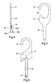
- FIG. 4 shows a side view of the hanger of FIG. 1 , when in use
- FIG. 5 shows a second embodiment of the present invention.
- FIG. 6 shows a front view of a third embodiment of the present invention.
- FIGS. 1 to 6 show a hanger 10 having a hook portion 12 connected to an intended upper end of a body portion 14 , and an elongate member 16 connected to an intended lower end of the body portion 14 .
- the length of the elongate member 16 is approximately the same as the length of the combined body portion 14 and hook portion 12 .
- the elongate member 16 has a male part of a one-way ‘snap-fit’ connector 18 at the end 20 , nearest the body portion 14 .
- the end 22 farthest from the body 10 of the elongate member 16 has an aperture 24 , which is designed to cooperate with the ‘one-way’ snap-fit connector 18 .
- the elongate member 16 is weakened in a transverse direction in three positions 26 a , 26 b and 26 c .
- the hanger 10 further comprises a region 28 on the body portion 14 on which a logo or identifying means can be printed or written.
- the hanger 10 is bevelled at both the end of the hook portion 12 and the end of the elongate member 16 .
- the hanger 10 is constructed from a plastics material.
- the elongate member 16 of the hanger 10 When in use, the elongate member 16 of the hanger 10 is threaded through a belt-loop of a pair of jeans (not shown). As shown in FIG. 4 , the elongate member 16 is then folded inwardly at weakened positions 26 a and 26 b and outwardly at 26 c , so that the aperture 24 is in line with the connector 18 . The section between weakened positions 26 a and 26 b defines a flat spacer 27 . The aperture 24 is pushed onto and engages the male snap-fit connector 18 . The male snap-fit connector 18 yields while the aperture 24 is pushed onto it due to the split in the top of the snap-fit connector 18 .
- the plastics material returns to its original position and the aperture 24 is prevented from passing back over the snap fit connector 18 . Therefore, the aperture 24 and the snap-fit connector 18 make a non-releasable connection such that the jeans are held securely on the hanger 10 and the ‘loop’ formed by the elongate member 16 hanger cannot be readily uncoupled.
- the hook portion 12 of the hanger 10 can then engage a hanging rail (not shown), with the item to be hung resting upon the spacer 27 .
- the elongate member 16 must be cut, preferably along one of the weakened regions 26 A 26 b 26 c.
- FIG. 5 shows a hanger 10 having the features shown in the first embodiment in FIGS. 1 to 4 , with the additional feature of a recessed area 30 of the body 14 opposite the arc of the hook portion 12 .
- the hook portion 12 engages a rail and the recessed area 30 reduces the risk of inadvertent disengagement of the hanger 10 .
- the hanger 10 is raised in order to be disengaged from the rail (not show), the user must draw the hanger 10 away from the rail in order to effect disengagement. If the user does not draw the hanger 10 away from the rail and continues raising the hanger 10 , the recessed area 30 will engage the rail and make it more difficult to remove the hanger 10 from the rail. Therefore, if the hanger 10 is unintentionally raised with respect to the rail, recessed area 30 will reduce the risk of disengagement of the hanger 10 .
- FIG. 6 shows a further embodiment of the present invention, wherein a split snap-fit connector 18 is positioned on the body portion 14 of the hanger 10 .
- a loop of metallic wire 32 is provided within the hanger 10 to reduce the likelihood of the hanger being easily removed from the item to which it is attached.
- a removal device (not shown), such as a guillotine, is used to cut the plastics material, preferably at 26 a or 26 b , allowing the hanger 10 to be removed from the item.
- the removal device may melt the plastics material of the hanger 10 and any reinforcement material so that the hanger 10 can be removed from the item.
- the removal device may be mounted to a surface near a cashier's desk so that once an item has been paid for, the hanger 10 and integral security device can be removed prior to the customer leaving the store. By using a surface mounted device for the removal of the hanger, the likelihood of a thief removing the hanger in-store is reduced.
- a security tag 34 is moulded into the hanger during manufacture and is wholly embedded within the body portion, thereby sealing it within the hanger.
- the connector 18 shown in the Figures may be releasable, or ‘two-way’, rather than unreleasable.
- the hanger can then be reused and is suitable for use domestically.
- the connector 18 is a releasable connector
- the item is removed from the hanger by releasing the connection and removing the elongate member 16 from the item.
- the hook portion 12 may be replaced with a closed aperture so that the hanger can be threaded onto a rail and retained on the rail.
- Such a construction may be useful in a hotel, where clothes hangers are often retained on a hanging rail to prevent theft of the hangers.
- the body portion 14 may comprise a magnetic portion, either in addition to or in place of the region 28 , so that a metal plate can be attached to the hanger 10 .
- the magnetic plate may contain a name, address, or an identifying number. Such a construction may be useful for identifying garments, for example coats in a cloakroom or garments in a dry-cleaner.
- a magnetic plate may be used on a metal hanger. This allows items to be identified quickly and easily from a rail and is more easily read than a label attached to the hanger either by sticky tape or string.
- connection members may be used in place of a snap-fit connector, for example, a hook and eye fastener, a ‘popper’ a button and hole, etc.
- the wire in FIG. 6 of may be a length that passes from the snap-fit connection member 18 to the aperture 24 , rather than a loop. This maintains the resistance of the elongate member against being cut, but requires a shorter length of wire.
- Loop is intended to mean a closed circuit but not necessarily a circle.
- EAS Electronic article surveillance
Landscapes
- Engineering & Computer Science (AREA)
- Mechanical Engineering (AREA)
- Holders For Apparel And Elements Relating To Apparel (AREA)
- Supports Or Holders For Household Use (AREA)
- Vehicle Step Arrangements And Article Storage (AREA)
Abstract
Description
Claims (18)
Applications Claiming Priority (5)
| Application Number | Priority Date | Filing Date | Title |
|---|---|---|---|
| GB1000483A GB2474314B (en) | 2010-01-13 | 2010-01-13 | Hanger |
| GB1000483.6 | 2010-01-13 | ||
| GB1015123A GB2474329B (en) | 2010-01-13 | 2010-09-10 | Hanger |
| GB1015123.1 | 2010-09-10 | ||
| PCT/GB2011/050046 WO2011086376A1 (en) | 2010-01-13 | 2011-01-13 | Hanger |
Related Parent Applications (1)
| Application Number | Title | Priority Date | Filing Date |
|---|---|---|---|
| PCT/GB2011/050046 A-371-Of-International WO2011086376A1 (en) | 2010-01-13 | 2011-01-13 | Hanger |
Related Child Applications (1)
| Application Number | Title | Priority Date | Filing Date |
|---|---|---|---|
| US14/639,472 Continuation US9820589B2 (en) | 2010-01-13 | 2015-03-05 | Hanger |
Publications (2)
| Publication Number | Publication Date |
|---|---|
| US20130015215A1 US20130015215A1 (en) | 2013-01-17 |
| US8994535B2 true US8994535B2 (en) | 2015-03-31 |
Family
ID=42028275
Family Applications (2)
| Application Number | Title | Priority Date | Filing Date |
|---|---|---|---|
| US13/521,867 Active 2031-08-07 US8994535B2 (en) | 2010-01-13 | 2011-01-13 | Hanger including depending elongate member foldable on itself to form flat bottom spacer |
| US14/639,472 Active US9820589B2 (en) | 2010-01-13 | 2015-03-05 | Hanger |
Family Applications After (1)
| Application Number | Title | Priority Date | Filing Date |
|---|---|---|---|
| US14/639,472 Active US9820589B2 (en) | 2010-01-13 | 2015-03-05 | Hanger |
Country Status (9)
| Country | Link |
|---|---|
| US (2) | US8994535B2 (en) |
| EP (2) | EP2965667B1 (en) |
| CA (1) | CA2840830C (en) |
| DK (2) | DK2523581T3 (en) |
| ES (2) | ES2552430T3 (en) |
| GB (3) | GB2474314B (en) |
| PL (2) | PL2523581T3 (en) |
| PT (2) | PT2523581E (en) |
| WO (1) | WO2011086376A1 (en) |
Cited By (4)
| Publication number | Priority date | Publication date | Assignee | Title |
|---|---|---|---|---|
| US20150173532A1 (en) * | 2010-01-13 | 2015-06-25 | The Janger Limited | Hanger |
| US20180037385A1 (en) * | 2016-08-03 | 2018-02-08 | Balanced Act LLC | Hair accessory holder |
| US20220406156A1 (en) * | 2019-11-01 | 2022-12-22 | Sekura Global Ip Llp | Security tag |
| US20230000271A1 (en) * | 2019-11-29 | 2023-01-05 | The Janger Limited | A hanger arrangement |
Families Citing this family (30)
| Publication number | Priority date | Publication date | Assignee | Title |
|---|---|---|---|---|
| GB2507323B (en) * | 2012-10-26 | 2014-11-12 | Mainetti Uk Ltd | A garment hanger |
| EP2784714B1 (en) * | 2013-03-28 | 2021-04-28 | Alcatel Lucent | Method of preventing access to sensitive data of a computing device |
| US9159256B2 (en) | 2013-10-12 | 2015-10-13 | Girard Jones | Apparatus for marketing a brand |
| GB2520653C (en) * | 2014-01-14 | 2018-12-26 | The Janger Ltd | A hanging device |
| USD767289S1 (en) * | 2014-08-11 | 2016-09-27 | The Janger Limited | Clothes hanger |
| AT517615B1 (en) * | 2016-01-21 | 2017-03-15 | Harald Malzahn Kunststoffverarbeitungs Gmbh | Hanger for hanging a product on a presentation display |
| US9975682B2 (en) * | 2016-03-07 | 2018-05-22 | B&G Plastics, Inc. | Jewelry display hanger with security tag |
| US20170355495A1 (en) | 2016-06-08 | 2017-12-14 | N2 Packaging Systems, Llc | Child resistant and senior friendly can lid |
| USD811755S1 (en) * | 2016-11-10 | 2018-03-06 | The Janger Limited | Clothes hanger |
| US11834237B2 (en) | 2017-06-07 | 2023-12-05 | N2 Packaging Systems, Llc | Child resistant double seam container lid adapter ring |
| US11958666B2 (en) | 2017-06-07 | 2024-04-16 | N2 Packaging Systems, Llc | Child resistant double seam container lid |
| CA179784S (en) * | 2017-08-17 | 2018-12-17 | The Janger Ltd | Hanger |
| WO2019147299A2 (en) * | 2018-01-29 | 2019-08-01 | N2 Packaging Systems, Llc | Re-sealable container for a controlled substance having a child resistant lid |
| CA182653S (en) * | 2018-01-29 | 2019-05-28 | The Janger Ltd | Clothes hanger |
| US11142930B2 (en) | 2018-02-02 | 2021-10-12 | B&G Plastics, Inc. | Earring security display hanger configured to secure dangle earrings and stud earrings |
| WO2020222708A2 (en) * | 2019-02-28 | 2020-11-05 | Yegenoglu Suendues Bennur | Practical ironing board with a hanger unit |
| WO2021011734A1 (en) | 2019-07-16 | 2021-01-21 | DriFlower, LLC | Vegetation hanger |
| CA3149878A1 (en) | 2019-09-30 | 2021-04-08 | Todd Chandler LARKINS | Hang harvesting system |
| US11937552B2 (en) | 2019-10-09 | 2024-03-26 | DriFlower, LLC | Vegetation hanger |
| USD956554S1 (en) * | 2019-12-13 | 2022-07-05 | House of Atlas, LLC | Hanger |
| USD905977S1 (en) * | 2020-01-10 | 2020-12-29 | Loluemade, Inc | Closet organizer |
| USD946289S1 (en) * | 2020-01-20 | 2022-03-22 | The Janger Limited | Clothes hanger |
| MX2022009152A (en) * | 2020-01-23 | 2023-03-10 | All Tag Corp | Electronic article surveillance devices. |
| US11930929B2 (en) | 2021-03-03 | 2024-03-19 | DriFlower, LLC | Vegetation hanging and drying system |
| CA3151193A1 (en) | 2021-03-16 | 2022-09-16 | DriFlower, LLC | System for hang harvesting vegetation |
| US12239224B2 (en) | 2021-04-06 | 2025-03-04 | DriFlower, LLC | Vegetation hanging and drying system and brackets thereof |
| US11910758B2 (en) | 2022-01-24 | 2024-02-27 | DriFlower, LLC | Vegetation hanger |
| USD1030426S1 (en) | 2022-01-24 | 2024-06-11 | DriFlower, LLC | Vegetation hanger |
| US11871704B2 (en) | 2022-04-20 | 2024-01-16 | DriFlower, LLC | Bracket assemblies of vegetation hanging and drying systems |
| USD1037799S1 (en) | 2022-09-26 | 2024-08-06 | DriFlower, LLC | Vegetation hanger |
Citations (7)
| Publication number | Priority date | Publication date | Assignee | Title |
|---|---|---|---|---|
| US5222638A (en) | 1992-01-07 | 1993-06-29 | B&G Plastics, Inc. | Hanger for dual prong belts |
| FR2714103A1 (en) | 1993-12-21 | 1995-06-23 | Mariotti Alain Gerard | Adjustable anti-theft hanger for displaying belts in shops |
| EP0771922A2 (en) | 1995-11-03 | 1997-05-07 | PLASTI-MAX SpA | Multi-purpose tag for irreversible fixing to objects displayed for sale |
| US6299039B1 (en) | 2000-09-18 | 2001-10-09 | Hung-Cheng Hsu | Article hanger |
| US20040217249A1 (en) | 2003-04-17 | 2004-11-04 | Eisenbraun Kenneth D. | Merchandising hanger |
| US20050099303A1 (en) | 2003-11-11 | 2005-05-12 | Zuckerman Andrew M. | Injection molded garment hanger |
| US7015815B1 (en) | 2003-11-19 | 2006-03-21 | Display Technologies, Inc. | Anti-theft hanger |
Family Cites Families (19)
| Publication number | Priority date | Publication date | Assignee | Title |
|---|---|---|---|---|
| US1510915A (en) * | 1922-09-28 | 1924-10-07 | Bartholdi Amlo | Garment hanger |
| GB232141A (en) * | 1924-12-17 | 1925-04-16 | Henry Collings | Improvements in appliances for facilitating the putting-on of garments |
| US3592343A (en) * | 1969-07-16 | 1971-07-13 | Dart Ind Inc | Travel tie hanger |
| US3685189A (en) * | 1969-11-24 | 1972-08-22 | David L Conger | Combination ski pants hanger and sales information display device |
| US3790045A (en) * | 1972-08-11 | 1974-02-05 | Y Rigel | Tie holder |
| US4023762A (en) * | 1976-01-09 | 1977-05-17 | John Thomas Batts, Inc. | Article suspension device |
| US4153189A (en) * | 1978-01-03 | 1979-05-08 | Hughes Allan F | Carrier for clothes hangers |
| US4212403A (en) * | 1978-02-27 | 1980-07-15 | Zeigler Bert A | Drapery hanger |
| GB8903582D0 (en) * | 1989-02-16 | 1989-04-05 | Leisuretime Products Limited | Goods hanging strap |
| US5584455A (en) * | 1992-07-03 | 1996-12-17 | Artemi; Paul | Device for holding garment hangers |
| FR2702353B1 (en) * | 1993-03-12 | 1995-06-02 | Patrick Lamy | Anti-theft device for glasses. |
| US5429284A (en) * | 1993-03-30 | 1995-07-04 | B&G Plastics, Inc. | Garment hanger for ties with plural openings |
| US5615810A (en) * | 1996-01-11 | 1997-04-01 | B&G Plastics, Inc. | Hanger for suspenders with trouser waistband snaps |
| US5988462A (en) * | 1998-10-19 | 1999-11-23 | B&G Plastics, Inc. | Security garment hanger |
| US6398086B1 (en) * | 1999-10-10 | 2002-06-04 | Erith L. Bennett | Modified apparel accessories rack |
| US7500586B2 (en) * | 2005-12-01 | 2009-03-10 | Danver Llc | Hanger for headbands and elastic ponytail loops |
| CN201260583Y (en) * | 2008-08-29 | 2009-06-24 | 陈正识 | Anti-dropping clothe hanger with wind-proof string |
| GB2474314B (en) * | 2010-01-13 | 2011-10-05 | May Trading | Hanger |
| US20150245724A1 (en) * | 2014-03-03 | 2015-09-03 | Kimberly Sut | Multifunctional clothing hanger |
-
2010
- 2010-01-13 GB GB1000483A patent/GB2474314B/en not_active Expired - Fee Related
- 2010-09-10 GB GB1015123A patent/GB2474329B/en active Active
-
2011
- 2011-01-13 CA CA2840830A patent/CA2840830C/en active Active
- 2011-01-13 ES ES11701550.3T patent/ES2552430T3/en active Active
- 2011-01-13 EP EP15179734.7A patent/EP2965667B1/en active Active
- 2011-01-13 ES ES15179734.7T patent/ES2684101T3/en active Active
- 2011-01-13 DK DK11701550.3T patent/DK2523581T3/en active
- 2011-01-13 EP EP11701550.3A patent/EP2523581B1/en active Active
- 2011-01-13 PL PL11701550T patent/PL2523581T3/en unknown
- 2011-01-13 PT PT117015503T patent/PT2523581E/en unknown
- 2011-01-13 PL PL15179734T patent/PL2965667T3/en unknown
- 2011-01-13 DK DK15179734.7T patent/DK2965667T3/en active
- 2011-01-13 US US13/521,867 patent/US8994535B2/en active Active
- 2011-01-13 WO PCT/GB2011/050046 patent/WO2011086376A1/en not_active Ceased
- 2011-01-13 PT PT15179734T patent/PT2965667T/en unknown
- 2011-07-07 GB GB1111662.1A patent/GB2492589A/en not_active Withdrawn
-
2015
- 2015-03-05 US US14/639,472 patent/US9820589B2/en active Active
Patent Citations (7)
| Publication number | Priority date | Publication date | Assignee | Title |
|---|---|---|---|---|
| US5222638A (en) | 1992-01-07 | 1993-06-29 | B&G Plastics, Inc. | Hanger for dual prong belts |
| FR2714103A1 (en) | 1993-12-21 | 1995-06-23 | Mariotti Alain Gerard | Adjustable anti-theft hanger for displaying belts in shops |
| EP0771922A2 (en) | 1995-11-03 | 1997-05-07 | PLASTI-MAX SpA | Multi-purpose tag for irreversible fixing to objects displayed for sale |
| US6299039B1 (en) | 2000-09-18 | 2001-10-09 | Hung-Cheng Hsu | Article hanger |
| US20040217249A1 (en) | 2003-04-17 | 2004-11-04 | Eisenbraun Kenneth D. | Merchandising hanger |
| US20050099303A1 (en) | 2003-11-11 | 2005-05-12 | Zuckerman Andrew M. | Injection molded garment hanger |
| US7015815B1 (en) | 2003-11-19 | 2006-03-21 | Display Technologies, Inc. | Anti-theft hanger |
Non-Patent Citations (1)
| Title |
|---|
| International Search Report for corresponding patent application No. PCT/GB2011/050046 dated Apr. 13, 2011. |
Cited By (7)
| Publication number | Priority date | Publication date | Assignee | Title |
|---|---|---|---|---|
| US20150173532A1 (en) * | 2010-01-13 | 2015-06-25 | The Janger Limited | Hanger |
| US9820589B2 (en) * | 2010-01-13 | 2017-11-21 | The Janger Limited | Hanger |
| US20180037385A1 (en) * | 2016-08-03 | 2018-02-08 | Balanced Act LLC | Hair accessory holder |
| US9957094B2 (en) * | 2016-08-03 | 2018-05-01 | Balanced Act LLC | Hair accessory holder |
| US20220406156A1 (en) * | 2019-11-01 | 2022-12-22 | Sekura Global Ip Llp | Security tag |
| US20230000271A1 (en) * | 2019-11-29 | 2023-01-05 | The Janger Limited | A hanger arrangement |
| US12262827B2 (en) * | 2019-11-29 | 2025-04-01 | The Janger Limited | Hanger arrangement |
Also Published As
| Publication number | Publication date |
|---|---|
| US20150173532A1 (en) | 2015-06-25 |
| PL2523581T3 (en) | 2016-01-29 |
| GB201000483D0 (en) | 2010-03-03 |
| ES2684101T3 (en) | 2018-10-01 |
| EP2965667A1 (en) | 2016-01-13 |
| EP2523581B1 (en) | 2015-08-05 |
| DK2523581T3 (en) | 2015-11-16 |
| GB2474329B (en) | 2011-10-12 |
| PL2965667T3 (en) | 2018-12-31 |
| EP2523581A1 (en) | 2012-11-21 |
| GB201015123D0 (en) | 2010-10-27 |
| GB2474329A (en) | 2011-04-13 |
| CA2840830C (en) | 2018-10-09 |
| US20130015215A1 (en) | 2013-01-17 |
| CA2840830A1 (en) | 2011-07-21 |
| EP2965667B1 (en) | 2018-05-16 |
| PT2965667T (en) | 2018-10-09 |
| GB2492589A (en) | 2013-01-09 |
| GB2474314A (en) | 2011-04-13 |
| ES2552430T3 (en) | 2015-11-27 |
| PT2523581E (en) | 2015-11-19 |
| WO2011086376A1 (en) | 2011-07-21 |
| US9820589B2 (en) | 2017-11-21 |
| GB201111662D0 (en) | 2011-08-24 |
| GB2474314B (en) | 2011-10-05 |
| DK2965667T3 (en) | 2018-08-27 |
Similar Documents
| Publication | Publication Date | Title |
|---|---|---|
| US8994535B2 (en) | Hanger including depending elongate member foldable on itself to form flat bottom spacer | |
| CN203825751U (en) | Multi-attachment reusable tag | |
| EP3582659B1 (en) | Garment hanger | |
| CN1168412C (en) | safety clothes rack | |
| JP2012519898A (en) | Security hard tag with attachment clip and attachment / detachment method | |
| US6036064A (en) | Hanger for garments and accessories | |
| JP2006280957A (en) | Two piece design of coordinate loop hangers | |
| US20090272771A1 (en) | Compact hanging clothing assembly | |
| CN106102521A (en) | Suspension arrangement and assembly | |
| US20190365131A1 (en) | Collapsible Hanger | |
| WO2018229106A1 (en) | Security tag | |
| US7318540B1 (en) | Indicator for garment hanger | |
| JPH1057206A (en) | Merchandise exhibition hanger | |
| EP3357374A1 (en) | Merchandising display element | |
| GB2090520A (en) | Anti-theft clothes hanger | |
| ITVI20010175A1 (en) | TIE HOLDER AND SIMILAR EQUIPPED WITH ANTI-THEFT MARKING |
Legal Events
| Date | Code | Title | Description |
|---|---|---|---|
| AS | Assignment |
Owner name: DELRAY DESIGN LIMITED, UNITED KINGDOM Free format text: ASSIGNMENT OF ASSIGNORS INTEREST;ASSIGNOR:COOTE, JOHN;REEL/FRAME:028960/0038 Effective date: 20120724 |
|
| AS | Assignment |
Owner name: THE JANGER LIMITED, UNITED KINGDOM Free format text: CHANGE OF NAME;ASSIGNOR:DELRAY DESIGN LIMITED;REEL/FRAME:031237/0028 Effective date: 20130424 |
|
| STCF | Information on status: patent grant |
Free format text: PATENTED CASE |
|
| MAFP | Maintenance fee payment |
Free format text: PAYMENT OF MAINTENANCE FEE, 4TH YR, SMALL ENTITY (ORIGINAL EVENT CODE: M2551); ENTITY STATUS OF PATENT OWNER: SMALL ENTITY Year of fee payment: 4 |
|
| AS | Assignment |
Owner name: IRWIN MITCHELL LLP, UNITED KINGDOM Free format text: SECURITY INTEREST;ASSIGNOR:THE JANGER LIMITED;REEL/FRAME:055126/0510 Effective date: 20201023 |
|
| MAFP | Maintenance fee payment |
Free format text: PAYMENT OF MAINTENANCE FEE, 8TH YR, SMALL ENTITY (ORIGINAL EVENT CODE: M2552); ENTITY STATUS OF PATENT OWNER: SMALL ENTITY Year of fee payment: 8 |
|
| AS | Assignment |
Owner name: THE JANGER LIMITED, ENGLAND AND WALES Free format text: RELEASE BY SECURED PARTY;ASSIGNOR:IRWIN MITCHELL LLP;REEL/FRAME:064842/0096 Effective date: 20201023 |