US8992357B2 - Segmented receiving housing hole, sliding core, tensioning device and traction mechanism drive - Google Patents
Segmented receiving housing hole, sliding core, tensioning device and traction mechanism drive Download PDFInfo
- Publication number
- US8992357B2 US8992357B2 US13/489,636 US201213489636A US8992357B2 US 8992357 B2 US8992357 B2 US 8992357B2 US 201213489636 A US201213489636 A US 201213489636A US 8992357 B2 US8992357 B2 US 8992357B2
- Authority
- US
- United States
- Prior art keywords
- opening
- segments
- receiving housing
- longitudinal axis
- traction mechanism
- Prior art date
- Legal status (The legal status is an assumption and is not a legal conclusion. Google has not performed a legal analysis and makes no representation as to the accuracy of the status listed.)
- Expired - Fee Related, expires
Links
Images


Classifications
-
- F—MECHANICAL ENGINEERING; LIGHTING; HEATING; WEAPONS; BLASTING
- F16—ENGINEERING ELEMENTS AND UNITS; GENERAL MEASURES FOR PRODUCING AND MAINTAINING EFFECTIVE FUNCTIONING OF MACHINES OR INSTALLATIONS; THERMAL INSULATION IN GENERAL
- F16H—GEARING
- F16H7/00—Gearings for conveying rotary motion by endless flexible members
- F16H7/08—Means for varying tension of belts, ropes, or chains
- F16H2007/0802—Actuators for final output members
- F16H2007/0806—Compression coil springs
-
- F—MECHANICAL ENGINEERING; LIGHTING; HEATING; WEAPONS; BLASTING
- F16—ENGINEERING ELEMENTS AND UNITS; GENERAL MEASURES FOR PRODUCING AND MAINTAINING EFFECTIVE FUNCTIONING OF MACHINES OR INSTALLATIONS; THERMAL INSULATION IN GENERAL
- F16H—GEARING
- F16H7/00—Gearings for conveying rotary motion by endless flexible members
- F16H7/08—Means for varying tension of belts, ropes, or chains
- F16H2007/0802—Actuators for final output members
- F16H2007/0812—Fluid pressure
-
- Y—GENERAL TAGGING OF NEW TECHNOLOGICAL DEVELOPMENTS; GENERAL TAGGING OF CROSS-SECTIONAL TECHNOLOGIES SPANNING OVER SEVERAL SECTIONS OF THE IPC; TECHNICAL SUBJECTS COVERED BY FORMER USPC CROSS-REFERENCE ART COLLECTIONS [XRACs] AND DIGESTS
- Y10—TECHNICAL SUBJECTS COVERED BY FORMER USPC
- Y10T—TECHNICAL SUBJECTS COVERED BY FORMER US CLASSIFICATION
- Y10T29/00—Metal working
- Y10T29/49—Method of mechanical manufacture
- Y10T29/4998—Combined manufacture including applying or shaping of fluent material
- Y10T29/49988—Metal casting
- Y10T29/49989—Followed by cutting or removing material
Definitions
- the invention relates to a receiving housing of a hydraulic tensioning device for a traction mechanism drive in an internal combustion engine, having an opening that extends along a longitudinal axis for receiving a piston that is actuated for deflecting a tensioning rail of the traction mechanism drive, wherein the receiving housing that surrounds the opening is a cast component, wherein moreover the opening comprises an inner contour having an inner surface that comprises at least first segments, and inclines for removing the workpiece from the mold are provided in the opening.
- Receiving housings of this type are used in traction mechanism drive, in which a traction mechanism, such as a chain or a belt, is deflected by a tensioning device that acts on a tensioning rail.
- the tensioning device is embodied in such a manner that it can push a piston out of an opening by hydraulic action.
- the opening receives a piston.
- Traction mechanism drives of this type are used in internal combustion engines, in particular in motor vehicles. Traction mechanism drives of this type are in use in particular in the area of timing assemblies. The traction mechanism transmits the torque of a crank shaft to a cam shaft and/or shafts of ancillary units.
- Tensioning devices are available that use the mechanical action method, whilst others use the hydraulic action method.
- a receiving housing is generally provided, out of which a piston is pushed as a result of a hydraulically provided force.
- Traction mechanism drives of this type are known for example from DE 10 2010 045 874 A1.
- Hydraulic tensioning devices are also known from DE 10 2008 033 260 A1.
- a hydraulic tensioning element is disclosed that is used in tensioning systems of traction mechanism drives, in particular chain drives in internal combustion engines, with this hydraulic tensioning element comprising a tensioning device housing with a blind hole that comprises on a side facing a traction mechanism an opening and on an opposite-lying side a base that comprises a through-going opening with a small diameter, wherein a pressure-loaded piston arranged in an axially displaceable manner and a hollow cylinder inserted in the piston are arranged inside the blind hole, wherein a device for securing purposes during transportation can be arranged between the tensioning device housing and piston.
- This tensioning element is characterized in that an oil discharge opening is arranged in the tensioning device housing to receive a pin for securing purposes during transportation, which opening is disposed at a shorter distance with respect to the base than with respect to the opening of the
- Hydraulic tensioning devices of this type having a receiving housing are used in the case of chain drive systems and belt drive systems for tensioning a traction mechanism in internal combustion engines.
- the object of the present invention is to prevent the previously known disadvantages and to offer an improvement, in which the receiving housing as far as possible does not require further machining.
- the two segments comprise surfaces that are directed into the inside of the opening and are aligned in parallel with the longitudinal axis.
- function-important and so-called function-unimportant segments are thus provided.
- the function-important segments are defined with respect to their relevant property as being important for removing a sliding core from the mold, namely during the primary shaping of a receiving housing.
- the function-unimportant segments however, have an important function when guiding the piston.
- a shape is achieved whereby the receiving bore is constructed such that this is subdivided into segments, which have primary function-important segments for removing the workpiece from the mold without or with extremely small inclines for removing the workpiece from the mold and secondary, function-unimportant segments that are of no importance as far as the function for removing the workpiece from the mold is concerned but are relevant for guiding the piston are provided.
- the receiving housing is cast from a metal material, such as aluminum or steel, or injection molded from a synthetic material. As the material sets, it shrinks in the region of the opening, which can also be described as a receiving bore, onto a core, such as a sliding core, contained therein.
- a core such as a sliding core
- the opening is embodied as a substantially cylindrical hole, approximately in the manner of a blind hole.
- a region can then be provided, into which hydraulic medium can flow and, provided that it is subjected to pressure, push out a piston inserted into the opening.
- the first segments comprise surfaces that are directed into the inside of the opening, are arranged in an inclined manner with respect to the longitudinal axis and form the inclines for removing the workpiece from the mold.
- These inclines for removing the workpiece from the mold comprise a gradient of from 1 to 10° with respect to the longitudinal axis of the hole.
- first segments and/or second segments extend longitudinally from an outer edge of the hole as far as a closed base of the hole.
- the radial extent of a first segment is greater than the radial extent of a second segment, preferably twice as large, three times as large or four times as large. In this manner, a particularly favorable balance of forces is achieved.
- a further exemplary embodiment is characterized in that the first segments are arranged alternately with the second segments along the periphery of the opening.
- a first segment follows a second segment that in turn is followed by a first segment as seen in the direction of the periphery of the opening.
- the invention relates also to a sliding core that comprises an outer contour that is complementary to the inner contour of the opening of the receiving housing in accordance with the invention and fits into the opening.
- the invention relates to a tensioning device having a receiving housing in accordance with the invention and a piston that fits into the opening. It also comprises a traction mechanism drive having a tensioning device in accordance with the invention, which tensioning device is supported on a tensioning rail of the traction mechanism drive.
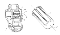
- FIG. 1 shows a perspective view of a receiving housing in accordance with the invention, where the sliding core and piston are not inserted,
- FIG. 2 shows a perspective illustration of a sliding core
- FIG. 3 shows a partial sectional illustration of a receiving housing in accordance with the invention and the sliding core that has been removed is illustrated to the side thereof,
- FIG. 4 shows a separate illustration of the sliding core as viewed from above
- FIG. 5 shows a sectional view through the sliding core along the line V from FIG. 4 .
- FIG. 1 illustrates a first embodiment of a receiving housing 1 in accordance with the invention.
- the receiving housing comprises an opening 2 that is embodied as a hole 3 in the manner of a blind hole.
- the receiving housing 1 is a single component made from a single material, for example a synthetic material or metal.
- the receiving housing 1 is manufactured from a light metal, namely an aluminum alloy.
- the opening 2 comprises an outer edge 4 that is arranged on the other side of a base 5 of the hole.
- the base 5 of the hole 3 or rather the hole base, is illustrated in FIG. 3 .
- the hole 3 extends along a longitudinal axis 6 of the receiving housing 1 .
- the longitudinal axis 6 is simultaneously also the longitudinal axis 6 of a slide 7 that is inserted into the hole 3 , as illustrated in FIGS. 2 , 3 and 4 .
- the longitudinal axis 6 is also indicated in FIG. 5 .
- the opening 2 comprises an inner contour that is subdivided into first segments 8 and second segments 9 .
- the first segments 8 comprise inwardly directed surfaces that are arranged in an inclined manner with respect to the longitudinal axis 6 .
- the second segments 9 comprise inner surfaces that are arranged directed inwards and extend in parallel with the longitudinal axis 6 .
- the first segments 8 and the second segments 9 extend from the edge 4 as far as the base 5 of the hole 3 .
- FIG. 2 illustrates a slide 7 that is also described as a sliding core 7 , wherein the outer contour of the sliding core 7 is complementary to the inner contour of the hole 3 .
- the sliding core 7 is used during the casting and/or injection molding method when manufacturing the receiving housing 1 . Upon completion of the casting or injection molding method, the sliding core 7 is removed in a direction 10 of removal from the mold, as illustrated in FIG. 3 .
- FIG. 3 also shows the piston 11 (in phantom lines) arranged in the opening 2 of the receiving housing 1 .
- the first segments 8 are arranged alternately with the second segments 9 as seen over the periphery of the slide 7 .
- the first segments 8 are aligned in parallel with the second segments 9 .
- the first segments 8 comprise a surface that includes an angle ⁇ relative to the longitudinal axis 6 .
- the angle ⁇ is a value between 1° and 10°, preferably 3° to 7°.
- the second segments 9 are arranged between the first segments 8 .
Abstract
Description
-
- 1 Receiving housing
- 2 Openings
- 3 Hole
- 4 Edge
- 5 Base
- 6 Longitudinal axes
- 7 Slide/Sliding core
- 8 First segments
- 9 Second segments
- 10 Direction of removal from the mold
Claims (9)
Applications Claiming Priority (3)
| Application Number | Priority Date | Filing Date | Title |
|---|---|---|---|
| DE102011077740 | 2011-06-17 | ||
| DE102011077740.7 | 2011-06-17 | ||
| DE102011077740A DE102011077740A1 (en) | 2011-06-17 | 2011-06-17 | Segmented receiving housing bore, slider core, tensioner and traction mechanism drive |
Publications (2)
| Publication Number | Publication Date |
|---|---|
| US20120322595A1 US20120322595A1 (en) | 2012-12-20 |
| US8992357B2 true US8992357B2 (en) | 2015-03-31 |
Family
ID=47228303
Family Applications (1)
| Application Number | Title | Priority Date | Filing Date |
|---|---|---|---|
| US13/489,636 Expired - Fee Related US8992357B2 (en) | 2011-06-17 | 2012-06-06 | Segmented receiving housing hole, sliding core, tensioning device and traction mechanism drive |
Country Status (3)
| Country | Link |
|---|---|
| US (1) | US8992357B2 (en) |
| DE (1) | DE102011077740A1 (en) |
| IN (1) | IN2012DE01012A (en) |
Families Citing this family (1)
| Publication number | Priority date | Publication date | Assignee | Title |
|---|---|---|---|---|
| JP6448983B2 (en) * | 2014-10-29 | 2019-01-09 | 株式会社椿本チエイン | Tensioner |
Citations (13)
| Publication number | Priority date | Publication date | Assignee | Title |
|---|---|---|---|---|
| US1535330A (en) * | 1919-07-17 | 1925-04-28 | Sperry Gyroscope Co Ltd | Method of centrifugal casting |
| US2085212A (en) * | 1934-03-02 | 1937-06-29 | George A Dornin | Apparatus for stripping ingots |
| US2323972A (en) * | 1941-06-23 | 1943-07-13 | Charles A Brauchler | Method of forging |
| US4743224A (en) * | 1986-05-24 | 1988-05-10 | Fuji Jukogyo Kabushiki Kaisha | Automatic belt tensioner |
| US4838840A (en) * | 1987-03-23 | 1989-06-13 | Fuji Jukogyo Kabushiki Kaisha | Automatic belt tensioner |
| US5137074A (en) * | 1990-10-09 | 1992-08-11 | The Cessna Aircraft Company | Spherical bearing overlay casting process |
| US6053831A (en) * | 1998-12-08 | 2000-04-25 | Borg-Warner Automotive, Inc. | Hydraulic tensioner with passage of variable cross-section between the piston and bore |
| US20040147349A1 (en) * | 2003-01-24 | 2004-07-29 | Markley George L. | Ratcheting hydraulic chain tensioner with rotational reset and locking means |
| US20080274289A1 (en) * | 2004-06-21 | 2008-11-06 | Akira Sakurai | Mold Device and Method of Manufacturing Cylinder Block |
| US20090011880A1 (en) * | 2007-07-03 | 2009-01-08 | Seiji Sato | Auto-tensioner |
| US20090313805A1 (en) * | 2007-08-17 | 2009-12-24 | Caterpillar Inc. | Two-Piece Compactor Wheel Tip |
| DE102008033260A1 (en) | 2008-07-15 | 2010-01-21 | Schaeffler Kg | Hydraulic clamping element i.e. hydraulic clamper for use in clamping system of chain drive of internal-combustion engine, has oil outlet opening provided for accommodation of transport lock pin |
| DE102010045874A1 (en) | 2009-09-21 | 2011-04-28 | Schaeffler Technologies Gmbh & Co. Kg | Clamping system for traction unit of flexible drive of internal-combustion engine, has damping unit that is provided with bore hole, which is brought in clamping arm |
-
2011
- 2011-06-17 DE DE102011077740A patent/DE102011077740A1/en not_active Withdrawn
-
2012
- 2012-04-02 IN IN1012DE2012 patent/IN2012DE01012A/en unknown
- 2012-06-06 US US13/489,636 patent/US8992357B2/en not_active Expired - Fee Related
Patent Citations (13)
| Publication number | Priority date | Publication date | Assignee | Title |
|---|---|---|---|---|
| US1535330A (en) * | 1919-07-17 | 1925-04-28 | Sperry Gyroscope Co Ltd | Method of centrifugal casting |
| US2085212A (en) * | 1934-03-02 | 1937-06-29 | George A Dornin | Apparatus for stripping ingots |
| US2323972A (en) * | 1941-06-23 | 1943-07-13 | Charles A Brauchler | Method of forging |
| US4743224A (en) * | 1986-05-24 | 1988-05-10 | Fuji Jukogyo Kabushiki Kaisha | Automatic belt tensioner |
| US4838840A (en) * | 1987-03-23 | 1989-06-13 | Fuji Jukogyo Kabushiki Kaisha | Automatic belt tensioner |
| US5137074A (en) * | 1990-10-09 | 1992-08-11 | The Cessna Aircraft Company | Spherical bearing overlay casting process |
| US6053831A (en) * | 1998-12-08 | 2000-04-25 | Borg-Warner Automotive, Inc. | Hydraulic tensioner with passage of variable cross-section between the piston and bore |
| US20040147349A1 (en) * | 2003-01-24 | 2004-07-29 | Markley George L. | Ratcheting hydraulic chain tensioner with rotational reset and locking means |
| US20080274289A1 (en) * | 2004-06-21 | 2008-11-06 | Akira Sakurai | Mold Device and Method of Manufacturing Cylinder Block |
| US20090011880A1 (en) * | 2007-07-03 | 2009-01-08 | Seiji Sato | Auto-tensioner |
| US20090313805A1 (en) * | 2007-08-17 | 2009-12-24 | Caterpillar Inc. | Two-Piece Compactor Wheel Tip |
| DE102008033260A1 (en) | 2008-07-15 | 2010-01-21 | Schaeffler Kg | Hydraulic clamping element i.e. hydraulic clamper for use in clamping system of chain drive of internal-combustion engine, has oil outlet opening provided for accommodation of transport lock pin |
| DE102010045874A1 (en) | 2009-09-21 | 2011-04-28 | Schaeffler Technologies Gmbh & Co. Kg | Clamping system for traction unit of flexible drive of internal-combustion engine, has damping unit that is provided with bore hole, which is brought in clamping arm |
Also Published As
| Publication number | Publication date |
|---|---|
| DE102011077740A1 (en) | 2012-12-20 |
| IN2012DE01012A (en) | 2015-07-24 |
| US20120322595A1 (en) | 2012-12-20 |
Similar Documents
| Publication | Publication Date | Title |
|---|---|---|
| AU2006286828B2 (en) | Piston comprising a circumferential radial recess located below an annular groove | |
| US6279456B1 (en) | Piston | |
| EP0826476B1 (en) | Method of manufacturing a plastic camshaft with a tubular metal insert | |
| US7197959B2 (en) | Coupling structure mountable to a rotatable shaft | |
| US20170241471A1 (en) | Composite vehicle shaft assembly | |
| US20170241299A1 (en) | Powertrain shaft assembly with core plug and method of manufacturing a shaft assembly | |
| CN107995936B (en) | Camshaft adjuster | |
| US8992357B2 (en) | Segmented receiving housing hole, sliding core, tensioning device and traction mechanism drive | |
| JP2011183529A (en) | Connecting rod rupture dividing device and rupture dividing method | |
| EP2738377B1 (en) | Process for manufacturing a cylinder crankcase | |
| CN101855034A (en) | Casting mold device | |
| WO2011104054A2 (en) | Device for variably adjusting the control times of gas exchange valves of an internal combustion engine | |
| CN110848361A (en) | Torque converter with variable pitch stator and method of manufacturing variable pitch stator | |
| US10619523B2 (en) | Cam shaft for engine and method for manufacturing same | |
| CN103328858A (en) | Belt and chain drive comprising a tensioner and a clamping element | |
| EP2362074B1 (en) | Device for variable valve timing on a combustion engine | |
| DE102014117874A1 (en) | Process and workpiece | |
| WO2014085285A2 (en) | Cylinder block with integrated oil jacket | |
| US20200398333A1 (en) | Casting device for engine cylinder block, casting mold for same, and casting method for same | |
| ITUB20159631A1 (en) | PULLEY GROUP OF A SPEED CHANGE? WITH CONTINUOUS CHANGE | |
| US11680540B2 (en) | Piston for an internal combustion engine and production method | |
| CN100460632C (en) | Method and apparatus for fabricating blade rotor | |
| CN107532688A (en) | The tensioning apparatus with retainer for chain and sprocket driving device | |
| CN110337336B (en) | Core group | |
| EP2018916A1 (en) | Cylinder body of engine and method of manufacturing the same |
Legal Events
| Date | Code | Title | Description |
|---|---|---|---|
| AS | Assignment |
Owner name: SCHAEFFLER TECHNOLOGIES AG & CO. KG, GERMANY Free format text: ASSIGNMENT OF ASSIGNORS INTEREST;ASSIGNOR:KASTNER, MICHAEL;REEL/FRAME:028327/0860 Effective date: 20120328 |
|
| STCF | Information on status: patent grant |
Free format text: PATENTED CASE |
|
| AS | Assignment |
Owner name: SCHAEFFLER TECHNOLOGIES GMBH & CO. KG, GERMANY Free format text: MERGER AND CHANGE OF NAME;ASSIGNORS:SCHAEFFLER TECHNOLOGIES AG & CO. KG;SCHAEFFLER VERWALTUNGS 5 GMBH;REEL/FRAME:037732/0228 Effective date: 20131231 Owner name: SCHAEFFLER TECHNOLOGIES AG & CO. KG, GERMANY Free format text: CHANGE OF NAME;ASSIGNOR:SCHAEFFLER TECHNOLOGIES GMBH & CO. KG;REEL/FRAME:037732/0347 Effective date: 20150101 |
|
| AS | Assignment |
Owner name: SCHAEFFLER TECHNOLOGIES AG & CO. KG, GERMANY Free format text: CORRECTIVE ASSIGNMENT TO CORRECT THE PROPERTY NUMBERS PREVIOUSLY RECORDED ON REEL 037732 FRAME 0347. ASSIGNOR(S) HEREBY CONFIRMS THE APP. NO. 14/553248 SHOULD BE APP. NO. 14/553258;ASSIGNOR:SCHAEFFLER TECHNOLOGIES GMBH & CO. KG;REEL/FRAME:040404/0530 Effective date: 20150101 |
|
| MAFP | Maintenance fee payment |
Free format text: PAYMENT OF MAINTENANCE FEE, 4TH YEAR, LARGE ENTITY (ORIGINAL EVENT CODE: M1551); ENTITY STATUS OF PATENT OWNER: LARGE ENTITY Year of fee payment: 4 |
|
| FEPP | Fee payment procedure |
Free format text: MAINTENANCE FEE REMINDER MAILED (ORIGINAL EVENT CODE: REM.); ENTITY STATUS OF PATENT OWNER: LARGE ENTITY |
|
| LAPS | Lapse for failure to pay maintenance fees |
Free format text: PATENT EXPIRED FOR FAILURE TO PAY MAINTENANCE FEES (ORIGINAL EVENT CODE: EXP.); ENTITY STATUS OF PATENT OWNER: LARGE ENTITY |
|
| STCH | Information on status: patent discontinuation |
Free format text: PATENT EXPIRED DUE TO NONPAYMENT OF MAINTENANCE FEES UNDER 37 CFR 1.362 |
|
| FP | Lapsed due to failure to pay maintenance fee |
Effective date: 20230331 |