US8991761B2 - Actuating mechanism for a vent door - Google Patents
Actuating mechanism for a vent door Download PDFInfo
- Publication number
- US8991761B2 US8991761B2 US13/191,763 US201113191763A US8991761B2 US 8991761 B2 US8991761 B2 US 8991761B2 US 201113191763 A US201113191763 A US 201113191763A US 8991761 B2 US8991761 B2 US 8991761B2
- Authority
- US
- United States
- Prior art keywords
- door
- aircraft
- vent
- vent door
- actuating mechanism
- Prior art date
- Legal status (The legal status is an assumption and is not a legal conclusion. Google has not performed a legal analysis and makes no representation as to the accuracy of the status listed.)
- Active, expires
Links
Images


Classifications
-
- B—PERFORMING OPERATIONS; TRANSPORTING
- B64—AIRCRAFT; AVIATION; COSMONAUTICS
- B64C—AEROPLANES; HELICOPTERS
- B64C1/00—Fuselages; Constructional features common to fuselages, wings, stabilising surfaces or the like
- B64C1/14—Windows; Doors; Hatch covers or access panels; Surrounding frame structures; Canopies; Windscreens accessories therefor, e.g. pressure sensors, water deflectors, hinges, seals, handles, latches, windscreen wipers
- B64C1/1407—Doors; surrounding frames
Definitions
- the invention relates to an actuating mechanism for a vent door and more particularly to an actuating mechanism for a vent door in an aircraft door that provides for the locking of the aircraft door while opening and closing said vent door.
- the open pressure vent door prevents the aircraft from being pressurized, thus requiring aircraft personnel to take note that there is a problem with the cabin door that requires attention.
- the aircraft will not take off, when the cabin is not pressurized.
- a typical drive linkage is arranged so that, before the latch assembly is actuated to open the aircraft cabin door, the pressure vent door is initially opened.
- the pressure vent door and the drive linkage are further constructed so that, when the aircraft's cabin pressure is greater than the ambient pressure, the pressure vent door will not open, and the drive linkage will not move.
- a pressure vent door assembly is well-suited for installation to an aircraft cabin door to prevent the door from being opened while the aircraft is in pressurized flight.
- the pressure vent door opener assembly locks out so as to inhibit movement of the handle shaft that would actuate the latch shaft and open the door.
- the pressure vent door opener assembly and the link to block the handle shaft form a fairly complex system.
- cargo aircrafts provide unique concerns and design considerations over passenger aircraft in that cargo aircrafts provide a large cargo door provided in the side of the fuselage. These cargo doors typically have their own latching mechanisms that are not tied into a vent-latch system. Since the cargo doors of cargo aircraft typically do not contain windows or openings therein, a vent-latch assembly similar to those provided in cabin doors of passenger aircraft cannot be installed within the cargo doors. In addition, due to the size of the cargo doors and the loads that the cargo aircraft carry, the cargo doors often require a secondary locking system or backup locking mechanism to prevent the cargo door from unwanted opening.
- U.S. Pat. No. 6,454,210 B1 discloses an aircraft vent and cargo door locking mechanism for ensuring the opening, closing, and locking of a cargo door in a cargo door opening formed in an aircraft fuselage.
- a latch assembly latches the cargo door to the fuselage, and the latch assembly moves between a latched position, wherein the cargo door is closed, and an unlatched position, wherein the cargo door may be opened.
- a locking assembly locks the latch assembly by moving between a locked position, wherein the latch assembly is maintained in the latched position, and an unlocked position, wherein the latch assembly may move to the unlatched position.
- a blocker provides a secondary locking mechanism by being slidable connected to the cargo door for movement between a blocked position, wherein the blocker engages and prohibits the locking and latch assemblies from moving to the unlocked and unlatched positions, respectively, and an unblocked position, wherein the blocker is disengaged from the locking and latch assemblies allowing the blocking and latch assemblies to move to the unlocked and unlatched positions, respectively.
- An actuator is operatively connected to the blocker for actuating the blocker between the blocked and unblocked positions.
- a vent door is mounted adjacent an opening provided in the aircraft fuselage wherein the opening and the vent door are remote from the cargo door.
- the actuator is operatively connected to the vent door for actuating the vent door between a vent door closed position and a vent door open position simultaneously with the actuation of the blocker.
- the pressure vent door and the drive linkage are further configured so that, in the event that the ambient pressure is substantially greater than the aircraft cabin pressure, the pressure vent door will open. This allows air to bleed into the aircraft to reduce the pressure differential between the inside of the aircraft and the ambient environment. The minimization of this pressure differential reduces the force imposed on the aircraft by the surrounding atmosphere.
- the pressure vent door and the drive linkage form a fairly complex system.
- an actuating mechanism for closing and opening of a vent door in an aircraft door comprising an electric motor drivingly connected to said vent door for driving said vent door in a closing position towards the aircraft door and reversely in an open position, said electric motor being as well drivingly connected to a further equipment such as a flight lock actuator.
- a control unit is provided controlling said electric motor.
- a return spring is provided acting on the vent door to an opening position via a mechanical connection to the electric motor.
- vent door may be arranged at any position in the aircraft door as the inventive actuating mechanism is free from any mechanism of the aircraft door and consequently any complex connection between any such mechanism and the vent door is rendered superfluous.
- vent door may be locked, opened or closed independently from the aircraft door.
- electric-motor is used for more than one equipment resulting in cost, weight and space benefit for less needed parts.
- the electro motor has limited power not allowing the drive of the vent door against the pressurized cabin of the aircraft with the advantages of allowing the use of a less expensive and less consuming electric motor, avoiding the need for supplemental safety devices in case of a malfunction of the electric motor and less forces on any inner or outer handle group.
- the electro-motor is not able to overcome a predetermined critical pressure difference from cabin to outside pressure,—said pressure difference acting in closing direction of the vent door—, to prevent any unintended opening of the vent door.
- the return spring has a limited force not allowing the drive of the vent door against the pressurized cabin of the aircraft with the advantages of allowing the use of less stressing springs, avoiding the need for supplemental locking and safety devices in case of a malfunction of the locking of said springs and less forces on any inner or outer handle group.
- the drive for the vent door allows a positioning of the vent door beyond its closing position in the aircraft door for removal of any layers of ice outside the aircraft door (deicing).
- ice build-up occurs particularly when the air temperature on one side of the vent door is much lower than the air temperature on the other side of the vent door.
- the ice builds up around the edges of the door, it can cause the door to become stuck in a closed position. This frequently occurs in commercial aircraft, since the temperatures outside of the aircraft at cruising altitude are usually well below 0° C.
- driving of the vent door beyond its closing position in the aircraft door i. e. by driving of the vent door initially further outside than the normal closing position before the opening process and thus outside the profile of the fuselage, any layers of ice outside the aircraft door can be broken and/or detached allowing subsequent opening operation towards inside as usual of the vent door.
- the drive for the vent door comprises a mechanical opening and closing system with a ball screw spindle and guide rails for reliable operation of opening and closing of the vent door relative to the aircraft door.
- a the mechanical opening and closing system is provided with an eccentric drive at the electric motor and a drive shaft from the electric motor towards said vent door for reliable opening and closing of the vent door.
- the return spring is linked to the eccentric drive of the electric motor for positioning of the vent door and the flight lock actuator in case of malfunction of the electric motor with a lock shaft being preferably provided to drive the flight lock actuator, said lock shaft being linked to the eccentric drive of the electric motor.
- inner and outer manual door shafts are provided for un-/locking of the aircraft door said manual door shafts being controlled by said flight lock actuator.
- said flight lock actuator is electromagnetic with preferably a gear mechanism and an uplock-hook.
- the flight lock actuator is provided with blocking means for a lifting mechanism of the aircraft door. This prevents the aircraft door from being opened while the cabin is pressurized.
- control unit comprises control software and/or hardware for communication and control of power switches and power electronics for control of the respective actuators.
- control unit comprises connection means to an aircraft computer via bus or discrete signals.
- a vent door seal is provided between the vent door and the aircraft door.
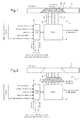
- FIG. 1 a first embodiment of an actuating mechanism according to the invention
- FIG. 2 the first embodiment of an actuating mechanism in a second position according to the invention
- FIG. 3 a second embodiment of an actuating mechanism according to the invention.
- FIG. 4 the second embodiment of the drive for an actuating mechanism in a second position according to the invention.
- a vent door 2 is shown in an aircraft door 3 in a closed position and according to FIG. 2 the vent door 2 is shown in an open position relative to said aircraft door 3 .
- An actuating mechanism 1 for the vent door 2 of the aircraft door 3 is driven by an electric motor 4 .
- the electric motor 4 is driving the vent door 2 for opening and closing relative to the aircraft door 3 to control pressure in a cabin (not shown) of an aircraft.
- the vent door 2 is provided with a bevel shaped circumference 5 for fitting into a complementary bevel shaped opening of the aircraft door 3 .
- a sealing (not shown) is provided between the bevel shaped circumference 5 of the vent door 2 and the bevel shaped opening of the aircraft door 3
- the actuating mechanism 1 is drivingly connected to the vent door 2 by a ball screw spindle 6 shifting the vent door 2 from the closed position towards the electric motor 4 to an open position or vice versa along guide rails 7 , 8 symmetrically arranged relative to the ball screw spindle 6 .
- the electric motor 4 may be a brushless direct current motor, a direct current motor, a Servo type or may be solenoids supplied with current at 28 V.
- the electric motor 1 is not strong enough to drive the vent door 2 into an open position against the pressure maintained inside the cabin of the aircraft relative to a low pressure outside the aircraft in a supposed high altitude thus avoiding any unintentional opening of the vent door 2 .
- the electric motor 4 is suitable to drive the vent door 2 after landing of the aircraft at least once for a short moment from a closed position further outside than the normal closing position and thus outside the outer profile of the aircraft door 3 , to break and/or detach any layers of ice outside the aircraft door 3 allowing subsequent opening of the vent door 2 without obstruction through ice layers.
- the electric motor 4 is controlled by a control unit 9 of adapted control electronics.
- the control unit 9 receives signals from an aircraft data bus or discrete signals providing parameters indicating the operating conditions of the aircraft, such as: A/C on wheels, indicating whether the aircraft is grounded, cabin pressure, aircraft velocity, open vent door 2 and aircraft door 3 latched and locked.
- a signal indicating e. g. to the control unit 9 the operating condition of the aircraft as “vent door 2 and aircraft door 3 latched and locked” blocks the electric motor 4 in its position.
- the control unit 9 processes said parameters for commands to the electric motor 4 and to a bus connected to a control unit (not shown) of a flight lock actuator.
- the control unit 9 comprises control software and/or hardware for communication and control of power switches (not shown) and power electronics (not shown) for control of actuators (not shown).
- the output of the control unit 9 indicates: “Vent door closed/opened” or “Overload” to a control unit of the flight lock actuator via the aircraft data bus or discrete signals.
- the data buses may be CAN, ARINC 429, etc. . . .
- FIG. 4 the vent door 2 is shown in an open position and according to FIG. 3 the vent door 2 is shown in a closed position.
- Corresponding features are referred to with the same reference numbers as in FIG. 1 or 2 .
- the electric motor 4 of the actuating mechanism 1 is provided with an eccentric drive 14 including an optional gear box.
- a return spring 12 is mechanically linked to the eccentric drive 14 of the electric motor 14 and biases the eccentric drive 14 to pull the vent door 2 towards an open position ( FIG. 4 ), said return spring 12 having a spring constant not allowing a sufficiently strong force to withdraw the vent door 2 from the closed position against any internal cabin pressure above an atmospheric pressure outside the grounded aircraft.
- the electric motor 4 is driving as well a flight lock actuator 10 as further equipment that controls the locking and subsequently the opening or closing of the aircraft door 3 .
- the flight lock actuator 10 is linked by means of a lock shaft 11 to the eccentric drive 14 of the electro motor 4 and interacts with an uplock-hook 16 , said eccentric drive 14 actuating as well the drive shaft 15 for opening and closing of the vent door 2 .
- An inner handle 13 is provided for unlocking of the aircraft door 3 , said inner handle 13 being blocked to keep the aircraft door 3 via said flight lock actuator 10 in its locked position by interacting with the electric motor 4 via the control unit 9 and signaling to the control unit 9 the operating condition of the aircraft as “vent door 2 and aircraft door 3 latched and locked”.
- the inner handle 13 may be pivoted manually for unlocking of the aircraft door 3 once the electric motor 1 is actuated by the control unit 9 of the aircraft to open vent door 2 ( FIG. 4 ), said flight lock actuator 10 being provided with blocking means for a lifting mechanism of the aircraft door 3 .
- Anti clockwise actuation of the electric motor 4 with the bias of return spring 12 opens the vent door 2 and allows unlocking of the flight lock actuator 10 after shifting lock shaft 11 upwardly. Clockwise actuation of the electric motor 4 against the bias of return spring 12 closes the vent door 2 after manual locking of the flight lock actuator 10 .
Abstract
Description
Claims (20)
Applications Claiming Priority (3)
| Application Number | Priority Date | Filing Date | Title |
|---|---|---|---|
| EP10400038.5 | 2010-08-05 | ||
| EP10400038 | 2010-08-05 | ||
| EP20100400038 EP2415663B1 (en) | 2010-08-05 | 2010-08-05 | Actuating mechanism for a vent door |
Publications (2)
| Publication Number | Publication Date |
|---|---|
| US20120032028A1 US20120032028A1 (en) | 2012-02-09 |
| US8991761B2 true US8991761B2 (en) | 2015-03-31 |
Family
ID=43533533
Family Applications (1)
| Application Number | Title | Priority Date | Filing Date |
|---|---|---|---|
| US13/191,763 Active 2032-02-20 US8991761B2 (en) | 2010-08-05 | 2011-07-27 | Actuating mechanism for a vent door |
Country Status (2)
| Country | Link |
|---|---|
| US (1) | US8991761B2 (en) |
| EP (1) | EP2415663B1 (en) |
Families Citing this family (4)
| Publication number | Priority date | Publication date | Assignee | Title |
|---|---|---|---|---|
| WO2014051628A1 (en) * | 2012-09-28 | 2014-04-03 | Hewlett-Packard Development Company, L.P. | Transition to an intermediate power state |
| US10689089B2 (en) * | 2016-04-01 | 2020-06-23 | Textron Innovations, Inc. | Entry handle for an aircraft doorway |
| EP3587243B1 (en) | 2018-06-29 | 2022-12-21 | Hamilton Sundstrand Corporation | Door closure mechanism |
| EP3859103A1 (en) * | 2020-01-29 | 2021-08-04 | Goodrich Actuation Systems Limited | Locking systems |
Citations (7)
| Publication number | Priority date | Publication date | Assignee | Title |
|---|---|---|---|---|
| US4497462A (en) | 1983-03-28 | 1985-02-05 | The Boeing Company | Outward opening electrically powered plug-type cargo door |
| US5163639A (en) * | 1990-07-11 | 1992-11-17 | Deutsche Airbus Gmbh | Door operating mechanism for opening and closing an aircraft door |
| US5305969A (en) | 1991-07-16 | 1994-04-26 | The Boeing Company | Aircraft door latch lock mechanism |
| US5337977A (en) * | 1993-01-29 | 1994-08-16 | The Boeing Company | Vent-latch interlock assembly for an aircraft door |
| US6116542A (en) * | 1997-09-03 | 2000-09-12 | Eurocopter Deutschland Gmbh | Door system for a passenger aircraft |
| GB2361743A (en) | 2000-04-28 | 2001-10-31 | Eurocopter Deutschland | Method and device for closing an aircraft door |
| US6454210B1 (en) | 2000-07-13 | 2002-09-24 | Wesley M. Plattner | Aircraft vent and cargo door locking mechanism |
-
2010
- 2010-08-05 EP EP20100400038 patent/EP2415663B1/en active Active
-
2011
- 2011-07-27 US US13/191,763 patent/US8991761B2/en active Active
Patent Citations (8)
| Publication number | Priority date | Publication date | Assignee | Title |
|---|---|---|---|---|
| US4497462A (en) | 1983-03-28 | 1985-02-05 | The Boeing Company | Outward opening electrically powered plug-type cargo door |
| US5163639A (en) * | 1990-07-11 | 1992-11-17 | Deutsche Airbus Gmbh | Door operating mechanism for opening and closing an aircraft door |
| US5305969A (en) | 1991-07-16 | 1994-04-26 | The Boeing Company | Aircraft door latch lock mechanism |
| US5337977A (en) * | 1993-01-29 | 1994-08-16 | The Boeing Company | Vent-latch interlock assembly for an aircraft door |
| US6116542A (en) * | 1997-09-03 | 2000-09-12 | Eurocopter Deutschland Gmbh | Door system for a passenger aircraft |
| GB2361743A (en) | 2000-04-28 | 2001-10-31 | Eurocopter Deutschland | Method and device for closing an aircraft door |
| US20020000493A1 (en) * | 2000-04-28 | 2002-01-03 | Hannes Erben | Method and device for closing a door of an aircraft |
| US6454210B1 (en) | 2000-07-13 | 2002-09-24 | Wesley M. Plattner | Aircraft vent and cargo door locking mechanism |
Non-Patent Citations (1)
| Title |
|---|
| Search Report and Written Opinion; Application No. EP 10400038; dated Dec. 5, 2011. |
Also Published As
| Publication number | Publication date |
|---|---|
| EP2415663B1 (en) | 2013-10-23 |
| US20120032028A1 (en) | 2012-02-09 |
| EP2415663A1 (en) | 2012-02-08 |
Similar Documents
| Publication | Publication Date | Title |
|---|---|---|
| CN101896400B (en) | Split handle for aircraft door | |
| US6454210B1 (en) | Aircraft vent and cargo door locking mechanism | |
| US5667169A (en) | Door system, particularly for a passenger plane | |
| EP2170698B1 (en) | Aircraft cargo door | |
| US20100294887A1 (en) | Pressurised aircraft door equipped with a vent flap | |
| US8991761B2 (en) | Actuating mechanism for a vent door | |
| US20070164572A9 (en) | Pressure sensing dead bolt | |
| US10752331B2 (en) | Aircraft emergency exit door with integrated mechanisms and method for opening/closing such a door | |
| EP3967595B1 (en) | Overwing exit door system | |
| EP3345826B1 (en) | Modular latch system | |
| US11697953B2 (en) | Door for separating two environments with different pressures | |
| KR20200083919A (en) | Door for cargo airplane | |
| EP3168139B1 (en) | Aircraft door assembly | |
| US11421464B2 (en) | Electromechanical door system for an aircraft | |
| US20220135201A1 (en) | Coaxial pressure lock assembly of an aircraft door | |
| US6951320B2 (en) | Lock mechanism for securing a door kinematics system and process of operating same | |
| US20180148156A1 (en) | System and method for flag door operation | |
| CN114458098B (en) | Electromechanical system for an aircraft | |
| EP3524510B1 (en) | Aircraft privacy door and door frame assembly | |
| US20220381070A1 (en) | Securing mechanism for securing a vehicle door | |
| US20080272607A1 (en) | Dual release actuator assembly | |
| EP3524512B1 (en) | Aircraft privacy door and door frame assembly | |
| CN115556918A (en) | Aircraft cabin door pressurization preventing device |
Legal Events
| Date | Code | Title | Description |
|---|---|---|---|
| AS | Assignment |
Owner name: EUROCOPTER DEUTSCHLAND GMBH, GERMANY Free format text: ASSIGNMENT OF ASSIGNORS INTEREST;ASSIGNORS:PRITZEN, THOMAS;BUHLER, MARKUS;TENDYRA, THOMAS;REEL/FRAME:026657/0579 Effective date: 20110713 |
|
| AS | Assignment |
Owner name: AIRBUS HELICOPTERS DEUTSCHLAND GMBH, GERMANY Free format text: CHANGE OF NAME;ASSIGNOR:EUROCOPTER DEUTSCHLAND GMBH;REEL/FRAME:032813/0051 Effective date: 20140107 |
|
| FEPP | Fee payment procedure |
Free format text: PAYOR NUMBER ASSIGNED (ORIGINAL EVENT CODE: ASPN); ENTITY STATUS OF PATENT OWNER: LARGE ENTITY |
|
| STCF | Information on status: patent grant |
Free format text: PATENTED CASE |
|
| MAFP | Maintenance fee payment |
Free format text: PAYMENT OF MAINTENANCE FEE, 4TH YEAR, LARGE ENTITY (ORIGINAL EVENT CODE: M1551); ENTITY STATUS OF PATENT OWNER: LARGE ENTITY Year of fee payment: 4 |
|
| MAFP | Maintenance fee payment |
Free format text: PAYMENT OF MAINTENANCE FEE, 8TH YEAR, LARGE ENTITY (ORIGINAL EVENT CODE: M1552); ENTITY STATUS OF PATENT OWNER: LARGE ENTITY Year of fee payment: 8 |