US8991144B2 - Conditioning device for a forage harvester - Google Patents

Conditioning device for a forage harvester Download PDF

Info

Publication number
US8991144B2
US8991144B2 US13/898,925 US201313898925A US8991144B2 US 8991144 B2 US8991144 B2 US 8991144B2 US 201313898925 A US201313898925 A US 201313898925A US 8991144 B2 US8991144 B2 US 8991144B2
Authority
US
United States
Prior art keywords
roller
conditioning device
circumference
rollers
axial direction
Prior art date
Legal status (The legal status is an assumption and is not a legal conclusion. Google has not performed a legal analysis and makes no representation as to the accuracy of the status listed.)
Active
Application number
US13/898,925
Other versions
US20130305678A1 (en
Inventor
Steffen Clauss
Manfred Engel
Current Assignee (The listed assignees may be inaccurate. Google has not performed a legal analysis and makes no representation or warranty as to the accuracy of the list.)
Deere and Co
Original Assignee
Deere and Co
Priority date (The priority date is an assumption and is not a legal conclusion. Google has not performed a legal analysis and makes no representation as to the accuracy of the date listed.)
Filing date
Publication date
Application filed by Deere and Co filed Critical Deere and Co
Assigned to DEERE & COMPANY reassignment DEERE & COMPANY ASSIGNMENT OF ASSIGNORS INTEREST (SEE DOCUMENT FOR DETAILS). Assignors: CLAUSS, STEFFEN, ENGEL, MANFRED
Publication of US20130305678A1 publication Critical patent/US20130305678A1/en
Application granted granted Critical
Publication of US8991144B2 publication Critical patent/US8991144B2/en
Active legal-status Critical Current
Anticipated expiration legal-status Critical

Links

Images

Classifications

    • AHUMAN NECESSITIES
    • A01AGRICULTURE; FORESTRY; ANIMAL HUSBANDRY; HUNTING; TRAPPING; FISHING
    • A01DHARVESTING; MOWING
    • A01D82/00Crop conditioners, i.e. machines for crushing or bruising stalks
    • AHUMAN NECESSITIES
    • A01AGRICULTURE; FORESTRY; ANIMAL HUSBANDRY; HUNTING; TRAPPING; FISHING
    • A01DHARVESTING; MOWING
    • A01D43/00Mowers combined with apparatus performing additional operations while mowing
    • A01D43/10Mowers combined with apparatus performing additional operations while mowing with means for crushing or bruising the mown crop
    • AHUMAN NECESSITIES
    • A01AGRICULTURE; FORESTRY; ANIMAL HUSBANDRY; HUNTING; TRAPPING; FISHING
    • A01DHARVESTING; MOWING
    • A01D82/00Crop conditioners, i.e. machines for crushing or bruising stalks
    • A01D82/02Rollers for crop conditioners

Definitions

  • the disclosure concerns a conditioning device for a forage harvester, with a first roller, which is profiled in the axial direction, and a second roller, which is also profiled in the axial direction, wherein the two rollers can be rotated, around their axes, in opposite directions and are aligned parallel to one another and the areas of one roller that have a larger diameter are opposite the areas of the other roller that have a smaller diameter, and with an element, in the axial direction, which is profiled in a manner complementary to the profile of the first roller and adjacent to the circumference of the first roller, for the removal of crop residues from the roller.
  • Forage harvesters are used to harvest whole plants or their parts, which are gathered from the field, during operation, by way of a harvesting attachment, compressed by pre-compression rollers, and are conducted to a chopping drum, whose chopper blades cut the plants, in conjunction with a counterblade. Subsequently, the cut plants or parts are optionally conducted to a conditioning device and conveyed to a discharge spout, by way of a post-acceleration device; the cut material is then loaded onto a transporting vehicle.
  • the harvested plants generally, are used as animal fodder or for the production of biogas.
  • the conditioning device usually comprises two or more rollers, driven in opposite directions, which are pre-tensioned, relative to one another, by a spring force and between which, the chopped material is conducted through. It is used during the corn harvest, to beat the grains contained in the chopped material and to improve the digestibility of the fodder.
  • rollers of the conditioning device are usually provided with teeth or edges extending in the axial direction, so that a noncircular, profiled cross section of the rollers is obtained (see DE 83 02 421 U1).
  • rollers profiled in the axial direction, which, for example, have flanks that are composed of straight-line inclined, rising (DE 41 22 338 A1) or stepped (DE 197 03 486 A1) or curved (DE 101 51 246 A1), or curved and straight sections (DE 10 2005 053 092 A1).
  • These rollers also have teeth in the circumferential directions and the areas of one roller that have a larger diameter are located opposite the areas of the other roller that have a smaller diameter, so that the (zigzag or meandering) processing gap between the rollers has at least an approximately constant width over its length.
  • rollers profiled in the axial direction
  • the processing gap is longer than with rollers that are not profiled in the axial direction.
  • the radii and thus the circumferential speeds of the points of the rollers, which mostly define the processing gap differ, which improves the processing of the harvested material.
  • a conditioning device for a forage harvester comprises a first roller, profiled in the axial direction, and a second roller, which is also profiled in the axial direction.
  • the two rollers can be rotated, around their axes, in opposite directions, and are aligned parallel to one another.
  • the areas of one roller that have a larger diameter are opposite the areas of the other roller that have a smaller diameter.
  • An element for the removal of crop remains from the roller is positioned adjacent to the circumference of the first roller and, in the axial direction, is shaped complementary to the profile of the first roller.
  • the area of the element, which is adjacent to the first roller and extends in the circumferential direction of the roller has a circular arc shape and extends over a part of the circumference of the first roller.
  • the element fills the area of the first roller that has a smaller diameter in the axial and circumferential directions and includes, with the first roller in the two aforementioned directions, a relatively small gap, in which only few crop residues or none at all can accumulate.
  • the rollers are composed of wedge-shaped or cylindrical disks of different sizes, which form an indentation defining an area with a smaller diameter, with an approximately triangular or rectangular cross section, and for this reason, reference is made to the state of the art according to DE 41 22 338 A1, DE 197 03 486 A1, DE 101 51 246 A1, and DE 10 2005 053 092 A1.
  • Each of the indentations of the first roller is correlated with an element.
  • FIG. 1 is a schematic side view of a forage harvester with a conditioning device
  • FIG. 2 is a perspective blown-up drawing of the conditioning device
  • FIG. 3 is an axial cross section through the lower roller of the conditioning device and an element for the removal of crop residues from the roller;
  • FIG. 4 is a cross section along the line 4 - 4 of FIG. 3 ;
  • FIG. 5 is a cross section along the line 5 - 5 of FIG. 3 .
  • a harvesting machine 10 shown in FIG. 1 , in the mode of a self-propelled forage harvester, is built on a frame 12 , which is carried by driven front wheels 14 and steerable rear wheels 16 .
  • the operation of the harvesting machine 10 is carried out from a driver's cabin 18 , from which a harvesting attachment 20 , suitable for the harvesting of stem plants, can be seen.
  • the harvesting attachment 20 which, in the embodiment shown, is a corn header, working independent of rows, material gathered from the ground—for example, corn, cereals, or the like, is conducted through upper pre-compression rollers 30 and lower pre-compression rollers 32 , to a chopper drum 22 , which chops it into small pieces and delivers it to a post-acceleration device 24 .
  • the material leaves the harvesting machine 10 to a trailer, travelling alongside, via a discharge device 26 , which can be adjusted in its position.
  • a conditioning device with two conditioning rollers 28 , 28 ′, through which the material to be conveyed is tangentially conducted to the conveying device 24 .
  • direction indication unless otherwise mentioned—such as, front, back, left, and right,—refer to the forward direction V of the harvesting machine 10 , which, in FIG. 1 , runs from right to left.
  • the material is transported through an entry conveyor with lower conveyor rollers 32 and upper conveyor rollers 30 , which are placed within an entry housing 36 .
  • the conveyor rollers 30 , 32 are also designated as pre-compression rollers, since the upper conveyor rollers 30 are pre-tensioned, by spring force, against the lower conveyor rollers 32 , so that the crops are pre-compressed between the conveyor rollers 30 , 32 and can be cut in a better manner.
  • the chopping blades distributed over the circumference of the chopping drum 22 , act together with a counter-cutter, so as to chop the material.
  • the rollers 28 , 28 ′ of the conditioning device are given in FIG. 2 , in a perspective blown-up representation.
  • the rollers 28 , 28 ′ comprise a centric shaft 38 , on which several disks 40 are mounted in a stationary manner.
  • the disks 40 are inclined, in the axial direction of the shafts 38 , on both flanks and have teeth in the circumferential direction, as described in DE 10 2005 053 092 A1.
  • halved disks 40 ′ are placed outside.
  • the disks 40 , 40 ′ thus form an undulating profile with sections with a large diameter, which correspond to the crests of waves, and indentations, corresponding to the troughs of waves, in which the rollers 28 , 28 ′ form sections with a smaller diameter.
  • the sections with a larger diameter of one roller 28 are placed opposite the indentations of the other roller 28 and vice-versa, so as to attain a processing gap with approximately a constant width over its length for the crops conducted through between the two rollers 28 , 28 ′.
  • the rollers 28 , 28 ′ are driven in opposite directions and the upper roller 28 ′ can escape upwards, against a spring force, opposite the lower roller 28 , supported rigidly within the framework of the forage harvester 10 .
  • scrapers 42 , 44 are correlated with the rollers 28 , 28 ′ on the discharge end, which are profiled corresponding to the axial profile of the rollers 28 , 28 ′.
  • elements 48 for the removal of crop residues from the roller 28 are placed on the inside of a bottom-side trough 46 , which enclose a part of the circumference of the lower roller 28 , downwards.
  • the elements 48 are adapted, in the axial direction, to the undulating profile of the roller 28 and are in the shape of a circular arc in the circumferential direction and extend over a sufficient angle range around the lower roller 28 —in the embodiment shown, around 180°, although larger or smaller wrap angles would also be possible.
  • the elements 48 thus fill the indentations in the roller 28 in both directions (axial direction and circumferential direction) with relatively small gaps, relative to the roller 28 , as one can see with the aid of the axial cross section of FIG. 3 and the radial cross section s of FIGS. 4 and 5 , and prevent crop residues from accumulating in the indentations.
  • the elements 48 can be produced from any material (metal, plastic, or wood) and can be separately affixed on the trough 46 , in particular, screwed on it.
  • the trough 46 can be produced as one piece with the elements 48 , preferably in an injection molding process, from plastic. It would also be possible to replace the trough 48 with another holder, open downwards (not shown), which is used only to affix the elements 48 . Such a holder or another trough 46 with elements 48 could also be correlated with the upper roller 28 ′.

Abstract

A conditioning device for a forage harvester is equipped with a first roller, profiled in the axial direction, and a second roller, also profiled in the axial direction. The two rollers are rotated, around their axes, in opposite directions and are aligned parallel to one another. An element, profiled, in the axial direction, in a manner complementary to the profile of the first roller and adjacent to the circumference of the first roller, for the removal of crop residues from the roller, extends in a circular arc over a part of the circumference of the first roller.

Description

FIELD OF THE DISCLOSURE
The disclosure concerns a conditioning device for a forage harvester, with a first roller, which is profiled in the axial direction, and a second roller, which is also profiled in the axial direction, wherein the two rollers can be rotated, around their axes, in opposite directions and are aligned parallel to one another and the areas of one roller that have a larger diameter are opposite the areas of the other roller that have a smaller diameter, and with an element, in the axial direction, which is profiled in a manner complementary to the profile of the first roller and adjacent to the circumference of the first roller, for the removal of crop residues from the roller.
BACKGROUND OF THE DISCLOSURE
Forage harvesters are used to harvest whole plants or their parts, which are gathered from the field, during operation, by way of a harvesting attachment, compressed by pre-compression rollers, and are conducted to a chopping drum, whose chopper blades cut the plants, in conjunction with a counterblade. Subsequently, the cut plants or parts are optionally conducted to a conditioning device and conveyed to a discharge spout, by way of a post-acceleration device; the cut material is then loaded onto a transporting vehicle. The harvested plants, generally, are used as animal fodder or for the production of biogas. The conditioning device usually comprises two or more rollers, driven in opposite directions, which are pre-tensioned, relative to one another, by a spring force and between which, the chopped material is conducted through. It is used during the corn harvest, to beat the grains contained in the chopped material and to improve the digestibility of the fodder.
The rollers of the conditioning device are usually provided with teeth or edges extending in the axial direction, so that a noncircular, profiled cross section of the rollers is obtained (see DE 83 02 421 U1).
Furthermore, embodiments of rollers, profiled in the axial direction, have been proposed, which, for example, have flanks that are composed of straight-line inclined, rising (DE 41 22 338 A1) or stepped (DE 197 03 486 A1) or curved (DE 101 51 246 A1), or curved and straight sections (DE 10 2005 053 092 A1). These rollers also have teeth in the circumferential directions and the areas of one roller that have a larger diameter are located opposite the areas of the other roller that have a smaller diameter, so that the (zigzag or meandering) processing gap between the rollers has at least an approximately constant width over its length. One advantage of these rollers, profiled in the axial direction, is that the processing gap is longer than with rollers that are not profiled in the axial direction. In addition, the radii and thus the circumferential speeds of the points of the rollers, which mostly define the processing gap, differ, which improves the processing of the harvested material.
On the other hand, in a manner different from rollers that are not profiled in the axial direction, crop residues accumulate in the indentations of the rollers profiled in the axial direction, which can be removed only insufficiently by scrapers adapted to the profile of the rollers. Such crop residues rub on the other rollers and on housing elements of the conditioning devices, which increases the wear and tear of the rollers and they can also lead to clogging of the conditioning device.
SUMMARY OF THE DISCLOSURE
The problem which is the basis of the disclosure is to be found in making available a conditioning device with rollers profiled in the axial direction, in which the aforementioned disadvantages do not appear or do so only to a reduced extent.
A conditioning device for a forage harvester comprises a first roller, profiled in the axial direction, and a second roller, which is also profiled in the axial direction. The two rollers can be rotated, around their axes, in opposite directions, and are aligned parallel to one another. The areas of one roller that have a larger diameter are opposite the areas of the other roller that have a smaller diameter. An element for the removal of crop remains from the roller is positioned adjacent to the circumference of the first roller and, in the axial direction, is shaped complementary to the profile of the first roller. The area of the element, which is adjacent to the first roller and extends in the circumferential direction of the roller, has a circular arc shape and extends over a part of the circumference of the first roller. In other words, the element fills the area of the first roller that has a smaller diameter in the axial and circumferential directions and includes, with the first roller in the two aforementioned directions, a relatively small gap, in which only few crop residues or none at all can accumulate.
In this way, crop residues are effectively removed from the first roller. In this way, clogging of the conditioning device needs no longer be feared or occurs more seldom.
Preferably, the rollers are composed of wedge-shaped or cylindrical disks of different sizes, which form an indentation defining an area with a smaller diameter, with an approximately triangular or rectangular cross section, and for this reason, reference is made to the state of the art according to DE 41 22 338 A1, DE 197 03 486 A1, DE 101 51 246 A1, and DE 10 2005 053 092 A1. Each of the indentations of the first roller is correlated with an element.
Several elements can be affixed separately on a holder or are produced, as one piece, with one another and a holder which joins them, for example, in an injection molding process, from plastic. In particular, there is the possibility of placing the element on the inside of a trough extending over a part of the circumference of the first roller or producing it as one piece with the trough. The first roller, which is correlated with the element for the removal of the crop residues, is located, as a rule, below the second roller. The trough, placed below the first roller, prevents the crops from falling downwards onto the field from the forage harvester and being lost to the harvesting process. It would, however, also be conceivable to equip with an element, alternatively or additionally, the second roller placed above the first roller; the element can also be affixed in a trough or on a holder.
BRIEF DESCRIPTION OF THE DRAWINGS
Embodiments of the disclosure are described in detail below with reference to the accompanying drawings wherein:
FIG. 1, is a schematic side view of a forage harvester with a conditioning device;
FIG. 2, is a perspective blown-up drawing of the conditioning device;
FIG. 3, is an axial cross section through the lower roller of the conditioning device and an element for the removal of crop residues from the roller;
FIG. 4, is a cross section along the line 4-4 of FIG. 3; and
FIG. 5, is a cross section along the line 5-5 of FIG. 3.
DETAILED DESCRIPTION OF THE DRAWINGS
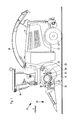
A harvesting machine 10, shown in FIG. 1, in the mode of a self-propelled forage harvester, is built on a frame 12, which is carried by driven front wheels 14 and steerable rear wheels 16. The operation of the harvesting machine 10 is carried out from a driver's cabin 18, from which a harvesting attachment 20, suitable for the harvesting of stem plants, can be seen. By way of the harvesting attachment 20, which, in the embodiment shown, is a corn header, working independent of rows, material gathered from the ground—for example, corn, cereals, or the like, is conducted through upper pre-compression rollers 30 and lower pre-compression rollers 32, to a chopper drum 22, which chops it into small pieces and delivers it to a post-acceleration device 24. The material leaves the harvesting machine 10 to a trailer, travelling alongside, via a discharge device 26, which can be adjusted in its position. Between the chopping drum 22 and the conveying device 24 extends a conditioning device with two conditioning rollers 28, 28′, through which the material to be conveyed is tangentially conducted to the conveying device 24. In the following, direction indication—unless otherwise mentioned—such as, front, back, left, and right,—refer to the forward direction V of the harvesting machine 10, which, in FIG. 1, runs from right to left.
Between the crop collecting device 20 and the chopping drum 22, the material is transported through an entry conveyor with lower conveyor rollers 32 and upper conveyor rollers 30, which are placed within an entry housing 36. The conveyor rollers 30, 32 are also designated as pre-compression rollers, since the upper conveyor rollers 30 are pre-tensioned, by spring force, against the lower conveyor rollers 32, so that the crops are pre-compressed between the conveyor rollers 30, 32 and can be cut in a better manner. The chopping blades, distributed over the circumference of the chopping drum 22, act together with a counter-cutter, so as to chop the material.
The rollers 28, 28′ of the conditioning device are given in FIG. 2, in a perspective blown-up representation. The rollers 28, 28′ comprise a centric shaft 38, on which several disks 40 are mounted in a stationary manner. In the embodiment represented, the disks 40 are inclined, in the axial direction of the shafts 38, on both flanks and have teeth in the circumferential direction, as described in DE 10 2005 053 092 A1. With the lower roller 28, halved disks 40′ are placed outside. The disks 40, 40′ thus form an undulating profile with sections with a large diameter, which correspond to the crests of waves, and indentations, corresponding to the troughs of waves, in which the rollers 28, 28′ form sections with a smaller diameter. The sections with a larger diameter of one roller 28 are placed opposite the indentations of the other roller 28 and vice-versa, so as to attain a processing gap with approximately a constant width over its length for the crops conducted through between the two rollers 28, 28′. During operation, the rollers 28, 28′ are driven in opposite directions and the upper roller 28′ can escape upwards, against a spring force, opposite the lower roller 28, supported rigidly within the framework of the forage harvester 10.
As shown in FIGS. 4 and 5, scrapers 42, 44 are correlated with the rollers 28, 28′ on the discharge end, which are profiled corresponding to the axial profile of the rollers 28, 28′.
In order to prevent crop residues from accumulating in the indentations of the lower roller 28, in spite of the use of the scraper 42, elements 48 for the removal of crop residues from the roller 28 are placed on the inside of a bottom-side trough 46, which enclose a part of the circumference of the lower roller 28, downwards. The elements 48 are adapted, in the axial direction, to the undulating profile of the roller 28 and are in the shape of a circular arc in the circumferential direction and extend over a sufficient angle range around the lower roller 28—in the embodiment shown, around 180°, although larger or smaller wrap angles would also be possible. The elements 48 thus fill the indentations in the roller 28 in both directions (axial direction and circumferential direction) with relatively small gaps, relative to the roller 28, as one can see with the aid of the axial cross section of FIG. 3 and the radial cross section s of FIGS. 4 and 5, and prevent crop residues from accumulating in the indentations.
The elements 48 can be produced from any material (metal, plastic, or wood) and can be separately affixed on the trough 46, in particular, screwed on it. Alternatively, the trough 46 can be produced as one piece with the elements 48, preferably in an injection molding process, from plastic. It would also be possible to replace the trough 48 with another holder, open downwards (not shown), which is used only to affix the elements 48. Such a holder or another trough 46 with elements 48 could also be correlated with the upper roller 28′.
Having described the preferred embodiment, it will become apparent that various modifications can be made without departing from the scope of the invention as defined in the accompanying claims.

Claims (10)

The invention claimed is:
1. A conditioning device for a forage harvester, the conditioning device having a first roller, profiled in the axial direction, and a second roller also profiled in the axial direction, wherein the two rollers are rotated, around their axes, in opposite directions and are aligned parallel to one another and areas of one roller that have a larger diameter are opposite areas of the other roller that have a smaller diameter, and having an element, which is profiled, in the axial direction, in a manner complementary to the profile of the first roller, and is adjacent to the circumference of the first roller, for the removal of crop residues from the roller, wherein the area of the element, adjacent to the first roller extends, in the shape of an arc, over a part of the circumference of the first roller.
2. The conditioning device according to claim 1, wherein the rollers are composed of wedge-shaped disks, between which an indentation, defining an area with a smaller diameter, is formed and each indentation of the first roller is correlated with the element.
3. The conditioning device according to claim 1, wherein several elements are one of separately affixed to a holder and produced as one piece with a holder joining them.
4. The conditioning device according to claim 1, wherein the element is one of placed on the inside of a trough extending over a part of the circumference of the first roller and produced as one piece with the trough.
5. The conditioning device according to claim 4, wherein the trough is located below the first roller and the second roller is positioned above the first roller.
6. A forage harvester with a conditioning device according to claim 1.
7. The conditioning device according to claim 1, wherein the area of the element, adjacent to the first roller extends, in the shape of an arc, over about 180° of the circumference of the first roller.
8. The conditioning device according to claim 1, further comprising:
a scraper.
9. The conditioning device according to claim 1, further comprising:
a second element, which is profiled, in the axial direction, in a manner complementary to the profile of the second roller, and is adjacent to the circumference of the second roller, for the removal of crop residues from the second roller, wherein the area of the second element, adjacent to the second roller extends, in the shape of an arc, over a part of the circumference of the second roller.
10. The conditioning device according to claim 9, wherein the area of the second element, adjacent to the second roller extends, in the shape of an arc, over about 180° of the circumference of the second roller.
US13/898,925 2012-05-21 2013-05-21 Conditioning device for a forage harvester Active US8991144B2 (en)

Applications Claiming Priority (3)

Application Number Priority Date Filing Date Title
DE102012208464.9 2012-05-21
DE102012208464A DE102012208464B3 (en) 2012-05-21 2012-05-21 Conditioning device for self-propelled forage harvester, for harvesting plants or parts of plants, has crop residues removing element whose surface is adjacent to roller and arcuately-extended around part of circumference of roller
DE102012208464 2012-05-21

Publications (2)

Publication Number Publication Date
US20130305678A1 US20130305678A1 (en) 2013-11-21
US8991144B2 true US8991144B2 (en) 2015-03-31

Family

ID=48608154

Family Applications (1)

Application Number Title Priority Date Filing Date
US13/898,925 Active US8991144B2 (en) 2012-05-21 2013-05-21 Conditioning device for a forage harvester

Country Status (2)

Country Link
US (1) US8991144B2 (en)
DE (1) DE102012208464B3 (en)

Cited By (3)

* Cited by examiner, † Cited by third party
Publication number Priority date Publication date Assignee Title
US20140166797A1 (en) * 2012-12-17 2014-06-19 Nolan Den Boer Processor disk and method of making
US10091938B2 (en) * 2015-11-04 2018-10-09 Gebrueder Busatis Gesellschaft M.B.H. Toothed crushing disk for a grain processor and method for producing the toothed crushing disk
US20230311131A1 (en) * 2020-09-11 2023-10-05 CBSM Mining Services Pty Ltd Gyratory roller crusher

Families Citing this family (5)

* Cited by examiner, † Cited by third party
Publication number Priority date Publication date Assignee Title
US9326445B1 (en) * 2013-05-20 2016-05-03 Phil Kooima Composite harvester spout
EP3051656A4 (en) 2014-10-21 2017-01-18 LG Chem, Ltd. System and method for correcting soc of battery
GB2535174B (en) * 2015-02-10 2020-10-21 Kverneland Group Kerteminde As Plant processing apparatus
CN109511388B (en) * 2018-11-29 2021-06-25 真木农业设备(安徽)有限公司 Maize straw recycling vehicle
CN113079809B (en) * 2021-04-09 2022-06-17 江苏杜林生态景观集团有限公司 Afforestation is with afforestation trimming means

Citations (9)

* Cited by examiner, † Cited by third party
Publication number Priority date Publication date Assignee Title
US4039434A (en) * 1975-01-17 1977-08-02 Massey-Ferguson Services N.V. Sugar cane harvester cane conveyor roller
DE8302421U1 (en) 1983-01-29 1985-12-19 Claas Ohg, 4834 Harsewinkel Forage harvester
US4708056A (en) * 1986-02-04 1987-11-24 Caribbean Industrial Research Institute Coconut dehusking machine
DE4122338A1 (en) 1991-07-05 1993-01-14 Land Technik Ag Schoenebeck REDUCTION DEVICE FOR FIELD CHOPPER
US5678396A (en) * 1995-08-23 1997-10-21 Deere & Company Sectioned grooved roller scraper
DE19703486A1 (en) 1997-01-31 1998-08-06 Deere & Co Post-shredding device
DE10151246A1 (en) 2001-10-17 2003-04-30 Hans Ottersbach Multicracker for forage harvester comprises two contra-rotating rollers which have corrugated surfaces, walls of corrugations being concave on one roller and correspondingly convex on other
US6837183B2 (en) * 2000-05-22 2005-01-04 Aspoey Bjoern Device for harvesting of and tending to shells and for cleaning of an associated shell collector in water
DE102005053092A1 (en) 2005-11-04 2007-05-10 Lacotec Agri Systems Gmbh Crushing device for crops

Family Cites Families (2)

* Cited by examiner, † Cited by third party
Publication number Priority date Publication date Assignee Title
US6234072B1 (en) * 2000-03-06 2001-05-22 John C. Kooima Grain husk cracking plate
DE102008017365A1 (en) * 2008-04-04 2009-10-08 Claas Selbstfahrende Erntemaschinen Gmbh Conditioning device for a harvester

Patent Citations (9)

* Cited by examiner, † Cited by third party
Publication number Priority date Publication date Assignee Title
US4039434A (en) * 1975-01-17 1977-08-02 Massey-Ferguson Services N.V. Sugar cane harvester cane conveyor roller
DE8302421U1 (en) 1983-01-29 1985-12-19 Claas Ohg, 4834 Harsewinkel Forage harvester
US4708056A (en) * 1986-02-04 1987-11-24 Caribbean Industrial Research Institute Coconut dehusking machine
DE4122338A1 (en) 1991-07-05 1993-01-14 Land Technik Ag Schoenebeck REDUCTION DEVICE FOR FIELD CHOPPER
US5678396A (en) * 1995-08-23 1997-10-21 Deere & Company Sectioned grooved roller scraper
DE19703486A1 (en) 1997-01-31 1998-08-06 Deere & Co Post-shredding device
US6837183B2 (en) * 2000-05-22 2005-01-04 Aspoey Bjoern Device for harvesting of and tending to shells and for cleaning of an associated shell collector in water
DE10151246A1 (en) 2001-10-17 2003-04-30 Hans Ottersbach Multicracker for forage harvester comprises two contra-rotating rollers which have corrugated surfaces, walls of corrugations being concave on one roller and correspondingly convex on other
DE102005053092A1 (en) 2005-11-04 2007-05-10 Lacotec Agri Systems Gmbh Crushing device for crops

Cited By (4)

* Cited by examiner, † Cited by third party
Publication number Priority date Publication date Assignee Title
US20140166797A1 (en) * 2012-12-17 2014-06-19 Nolan Den Boer Processor disk and method of making
US9833785B2 (en) * 2012-12-17 2017-12-05 Kooima Company Method of making a processor disk
US10091938B2 (en) * 2015-11-04 2018-10-09 Gebrueder Busatis Gesellschaft M.B.H. Toothed crushing disk for a grain processor and method for producing the toothed crushing disk
US20230311131A1 (en) * 2020-09-11 2023-10-05 CBSM Mining Services Pty Ltd Gyratory roller crusher

Also Published As

Publication number Publication date
DE102012208464B3 (en) 2013-07-04
US20130305678A1 (en) 2013-11-21

Similar Documents

Publication Publication Date Title
US8991144B2 (en) Conditioning device for a forage harvester
CA2894901C (en) Concave with crop guidance features
US7213781B2 (en) Cutterhead
US9750190B2 (en) Harvesting head upper belt conveyor compressing crop against a center belt conveyor
EP2168427A1 (en) Harvesting machine
US9326448B2 (en) Roller shell for a conditioning roller
US9386745B2 (en) Corn header for a forage harvester including a side separating mechanism
US20110047949A1 (en) Double tapered knife rolls
CN102986363B (en) Multi-purpose agricultural harvester
CN205596643U (en) Comminution device of stem stalk debris after harvester is threshed
US6910325B2 (en) Baler
US8984851B2 (en) Chopper attachment to improve conditioning of bio-mass type crops
US4083167A (en) Multi-row crop header
CA3079456A1 (en) Corn stalk roll drive system
US8829389B2 (en) Helical bar concave
CN105409434B (en) A kind of stalk recovery vehicle
KR101364181B1 (en) Baler
US20140290198A1 (en) Crop Residue Baler Integrated with Harvester, Method for Baling Crop Residue, and Resulting Trapezoidal Crop Residue Bale
CN105493748A (en) Corn harvester ensiling/yellow corn silage dual-purpose header
CN211267711U (en) Full-automatic combined harvesting and baling integrated machine
RU2572204C2 (en) Truck combine for harvesting roughage feed
CN207167101U (en) Multifunctional material bundling coating combine
US10470369B2 (en) Agricultural vehicle with active edge windrow chute
US20130167501A1 (en) Camless pickup wrapper
US20200236857A1 (en) Roller shell for a conditioning roller

Legal Events

Date Code Title Description
AS Assignment

Owner name: DEERE & COMPANY, ILLINOIS

Free format text: ASSIGNMENT OF ASSIGNORS INTEREST;ASSIGNORS:CLAUSS, STEFFEN;ENGEL, MANFRED;REEL/FRAME:030858/0176

Effective date: 20130524

STCF Information on status: patent grant

Free format text: PATENTED CASE

MAFP Maintenance fee payment

Free format text: PAYMENT OF MAINTENANCE FEE, 4TH YEAR, LARGE ENTITY (ORIGINAL EVENT CODE: M1551); ENTITY STATUS OF PATENT OWNER: LARGE ENTITY

Year of fee payment: 4

MAFP Maintenance fee payment

Free format text: PAYMENT OF MAINTENANCE FEE, 8TH YEAR, LARGE ENTITY (ORIGINAL EVENT CODE: M1552); ENTITY STATUS OF PATENT OWNER: LARGE ENTITY

Year of fee payment: 8