US8991117B1 - Solar and rainwater tower - Google Patents
Solar and rainwater tower Download PDFInfo
- Publication number
- US8991117B1 US8991117B1 US14/270,040 US201414270040A US8991117B1 US 8991117 B1 US8991117 B1 US 8991117B1 US 201414270040 A US201414270040 A US 201414270040A US 8991117 B1 US8991117 B1 US 8991117B1
- Authority
- US
- United States
- Prior art keywords
- solar panel
- pedestal
- support module
- hand
- support
- Prior art date
- Legal status (The legal status is an assumption and is not a legal conclusion. Google has not performed a legal analysis and makes no representation as to the accuracy of the status listed.)
- Active
Links
- NJPPVKZQTLUDBO-UHFFFAOYSA-N novaluron Chemical compound C1=C(Cl)C(OC(F)(F)C(OC(F)(F)F)F)=CC=C1NC(=O)NC(=O)C1=C(F)C=CC=C1F NJPPVKZQTLUDBO-UHFFFAOYSA-N 0.000 claims abstract description 82
- 238000001556 precipitation Methods 0.000 claims abstract description 37
- 238000012546 transfer Methods 0.000 claims description 4
- 238000006243 chemical reaction Methods 0.000 abstract 1
- 239000013505 freshwater Substances 0.000 abstract 1
- 230000000712 assembly Effects 0.000 description 11
- 238000000429 assembly Methods 0.000 description 11
- XLYOFNOQVPJJNP-UHFFFAOYSA-N water Substances O XLYOFNOQVPJJNP-UHFFFAOYSA-N 0.000 description 8
- 230000008901 benefit Effects 0.000 description 5
- 230000005611 electricity Effects 0.000 description 5
- 239000002803 fossil fuel Substances 0.000 description 4
- 230000001965 increasing effect Effects 0.000 description 4
- 238000000034 method Methods 0.000 description 3
- CURLTUGMZLYLDI-UHFFFAOYSA-N Carbon dioxide Chemical compound O=C=O CURLTUGMZLYLDI-UHFFFAOYSA-N 0.000 description 2
- 230000001143 conditioned effect Effects 0.000 description 2
- 230000003750 conditioning effect Effects 0.000 description 2
- 238000010276 construction Methods 0.000 description 2
- 238000013461 design Methods 0.000 description 2
- 230000007613 environmental effect Effects 0.000 description 2
- 239000003208 petroleum Substances 0.000 description 2
- 238000010248 power generation Methods 0.000 description 2
- 230000002250 progressing effect Effects 0.000 description 2
- 238000010521 absorption reaction Methods 0.000 description 1
- 238000003916 acid precipitation Methods 0.000 description 1
- 239000010426 asphalt Substances 0.000 description 1
- 235000012206 bottled water Nutrition 0.000 description 1
- 239000003990 capacitor Substances 0.000 description 1
- 229910002092 carbon dioxide Inorganic materials 0.000 description 1
- 239000001569 carbon dioxide Substances 0.000 description 1
- 239000003245 coal Substances 0.000 description 1
- 238000011161 development Methods 0.000 description 1
- 239000003651 drinking water Substances 0.000 description 1
- 238000005265 energy consumption Methods 0.000 description 1
- 239000003344 environmental pollutant Substances 0.000 description 1
- 239000000446 fuel Substances 0.000 description 1
- 239000005431 greenhouse gas Substances 0.000 description 1
- 238000003306 harvesting Methods 0.000 description 1
- 230000001939 inductive effect Effects 0.000 description 1
- 230000013011 mating Effects 0.000 description 1
- 238000012986 modification Methods 0.000 description 1
- 230000004048 modification Effects 0.000 description 1
- 231100000719 pollutant Toxicity 0.000 description 1
Images


Classifications
-
- H—ELECTRICITY
- H02—GENERATION; CONVERSION OR DISTRIBUTION OF ELECTRIC POWER
- H02S—GENERATION OF ELECTRIC POWER BY CONVERSION OF INFRARED RADIATION, VISIBLE LIGHT OR ULTRAVIOLET LIGHT, e.g. USING PHOTOVOLTAIC [PV] MODULES
- H02S30/00—Structural details of PV modules other than those related to light conversion
-
- H01L31/0482—
-
- F—MECHANICAL ENGINEERING; LIGHTING; HEATING; WEAPONS; BLASTING
- F24—HEATING; RANGES; VENTILATING
- F24S—SOLAR HEAT COLLECTORS; SOLAR HEAT SYSTEMS
- F24S25/00—Arrangement of stationary mountings or supports for solar heat collector modules
- F24S25/60—Fixation means, e.g. fasteners, specially adapted for supporting solar heat collector modules
- F24S25/61—Fixation means, e.g. fasteners, specially adapted for supporting solar heat collector modules for fixing to the ground or to building structures
-
- E—FIXED CONSTRUCTIONS
- E04—BUILDING
- E04D—ROOF COVERINGS; SKY-LIGHTS; GUTTERS; ROOF-WORKING TOOLS
- E04D13/00—Special arrangements or devices in connection with roof coverings; Protection against birds; Roof drainage; Sky-lights
-
- E—FIXED CONSTRUCTIONS
- E04—BUILDING
- E04H—BUILDINGS OR LIKE STRUCTURES FOR PARTICULAR PURPOSES; SWIMMING OR SPLASH BATHS OR POOLS; MASTS; FENCING; TENTS OR CANOPIES, IN GENERAL
- E04H6/00—Buildings for parking cars, rolling-stock, aircraft, vessels or like vehicles, e.g. garages
-
- F24J2/5245—
-
- F—MECHANICAL ENGINEERING; LIGHTING; HEATING; WEAPONS; BLASTING
- F24—HEATING; RANGES; VENTILATING
- F24S—SOLAR HEAT COLLECTORS; SOLAR HEAT SYSTEMS
- F24S25/00—Arrangement of stationary mountings or supports for solar heat collector modules
- F24S25/10—Arrangement of stationary mountings or supports for solar heat collector modules extending in directions away from a supporting surface
- F24S25/12—Arrangement of stationary mountings or supports for solar heat collector modules extending in directions away from a supporting surface using posts in combination with upper profiles
-
- F—MECHANICAL ENGINEERING; LIGHTING; HEATING; WEAPONS; BLASTING
- F24—HEATING; RANGES; VENTILATING
- F24S—SOLAR HEAT COLLECTORS; SOLAR HEAT SYSTEMS
- F24S30/00—Arrangements for moving or orienting solar heat collector modules
- F24S30/40—Arrangements for moving or orienting solar heat collector modules for rotary movement
- F24S30/42—Arrangements for moving or orienting solar heat collector modules for rotary movement with only one rotation axis
- F24S30/425—Horizontal axis
-
- H—ELECTRICITY
- H01—ELECTRIC ELEMENTS
- H01L—SEMICONDUCTOR DEVICES NOT COVERED BY CLASS H10
- H01L31/00—Semiconductor devices sensitive to infrared radiation, light, electromagnetic radiation of shorter wavelength or corpuscular radiation and specially adapted either for the conversion of the energy of such radiation into electrical energy or for the control of electrical energy by such radiation; Processes or apparatus specially adapted for the manufacture or treatment thereof or of parts thereof; Details thereof
- H01L31/04—Semiconductor devices sensitive to infrared radiation, light, electromagnetic radiation of shorter wavelength or corpuscular radiation and specially adapted either for the conversion of the energy of such radiation into electrical energy or for the control of electrical energy by such radiation; Processes or apparatus specially adapted for the manufacture or treatment thereof or of parts thereof; Details thereof adapted as photovoltaic [PV] conversion devices
- H01L31/052—Cooling means directly associated or integrated with the PV cell, e.g. integrated Peltier elements for active cooling or heat sinks directly associated with the PV cells
-
- H—ELECTRICITY
- H02—GENERATION; CONVERSION OR DISTRIBUTION OF ELECTRIC POWER
- H02S—GENERATION OF ELECTRIC POWER BY CONVERSION OF INFRARED RADIATION, VISIBLE LIGHT OR ULTRAVIOLET LIGHT, e.g. USING PHOTOVOLTAIC [PV] MODULES
- H02S20/00—Supporting structures for PV modules
- H02S20/30—Supporting structures being movable or adjustable, e.g. for angle adjustment
-
- H—ELECTRICITY
- H02—GENERATION; CONVERSION OR DISTRIBUTION OF ELECTRIC POWER
- H02S—GENERATION OF ELECTRIC POWER BY CONVERSION OF INFRARED RADIATION, VISIBLE LIGHT OR ULTRAVIOLET LIGHT, e.g. USING PHOTOVOLTAIC [PV] MODULES
- H02S40/00—Components or accessories in combination with PV modules, not provided for in groups H02S10/00 - H02S30/00
- H02S40/30—Electrical components
- H02S40/34—Electrical components comprising specially adapted electrical connection means to be structurally associated with the PV module, e.g. junction boxes
-
- Y—GENERAL TAGGING OF NEW TECHNOLOGICAL DEVELOPMENTS; GENERAL TAGGING OF CROSS-SECTIONAL TECHNOLOGIES SPANNING OVER SEVERAL SECTIONS OF THE IPC; TECHNICAL SUBJECTS COVERED BY FORMER USPC CROSS-REFERENCE ART COLLECTIONS [XRACs] AND DIGESTS
- Y02—TECHNOLOGIES OR APPLICATIONS FOR MITIGATION OR ADAPTATION AGAINST CLIMATE CHANGE
- Y02E—REDUCTION OF GREENHOUSE GAS [GHG] EMISSIONS, RELATED TO ENERGY GENERATION, TRANSMISSION OR DISTRIBUTION
- Y02E10/00—Energy generation through renewable energy sources
- Y02E10/40—Solar thermal energy, e.g. solar towers
- Y02E10/47—Mountings or tracking
-
- Y—GENERAL TAGGING OF NEW TECHNOLOGICAL DEVELOPMENTS; GENERAL TAGGING OF CROSS-SECTIONAL TECHNOLOGIES SPANNING OVER SEVERAL SECTIONS OF THE IPC; TECHNICAL SUBJECTS COVERED BY FORMER USPC CROSS-REFERENCE ART COLLECTIONS [XRACs] AND DIGESTS
- Y02—TECHNOLOGIES OR APPLICATIONS FOR MITIGATION OR ADAPTATION AGAINST CLIMATE CHANGE
- Y02E—REDUCTION OF GREENHOUSE GAS [GHG] EMISSIONS, RELATED TO ENERGY GENERATION, TRANSMISSION OR DISTRIBUTION
- Y02E10/00—Energy generation through renewable energy sources
- Y02E10/50—Photovoltaic [PV] energy
Definitions
- the present disclosure generally relates to parking lot solar power collecting structures. More specifically, the present invention pertains to highly-adaptable expandable interlocking tower modules providing vehicle covering, solar energy collection and rainwater collection.
- Electrically powered vehicles differ from fossil fuel-powered vehicles in that the electricity they consume can be generated from a wide range of sources, including fossil fuels, nuclear power, and renewable sources such as solar power, and wind power or any combination thereof.
- the electricity can be stored on board the vehicle using a battery, flywheel, or super capacitors.
- the primary means of storage on the vehicle are on-board rechargeable electric batteries. While a certain amount of electricity can be generated from excess kinetic energy during movement of the vehicle, the batteries are typically recharged while the vehicle is stationary and connected to a charging station.
- Electric vehicle charging stations are elements in an infrastructure that supply electric energy for the recharging of plug-in electric vehicles, such as all-electric cars and plug-in hybrids.
- plug-in hybrid electric vehicle and battery powered electric vehicle ownership expands, there is a growing need for widely distributed publicly accessible charging stations.
- charging stations are on-street facilities provided by electric utility companies, mobile charging stations have also been recently introduced.
- Some of the special charging stations provide one or a range of heavy-duty or special connectors or charging without a physical connection using parking places equipped with inductive charging mats.
- the present invention provides a system that successfully addresses all of the aforementioned, previously unresolved, issues by way of a unique interlocking modular structure, particularly adapted for efficient and effective deployment upon a parking lot ground surface.
- a portable interlocking solar energy and precipitation collection module assembly which comprises:
- a left-hand support module comprising:
- a right-hand support module comprising:
- each solar panel mounting surface having a concave surface contour including a central drainage aperture through which water from rain, snow and related states of weather precipitation can be conveniently collected and stored within the module, uncontaminated by the ground, for future consumption.
- the modular configuration is adapted to be easily and efficiently electrically connected to an adjacent power grid in order to selectively transfer collected and stored power to a local power grid.
- each modular unit has a unique free-standing construction, absent any vertical walls, which includes a single thin profile support leg supported upon the underlying ground surface.
- This unique configuration tends to provide minimal resistance to high airflow; thereby, minimizing the likelihood for structural damage during high-wind weather events.
- the wall-less modular unit configuration increases the space beneath the support upper platform portion of the structure, thereby facilitating vehicle maneuverability and supporting improved traffic mobility about the erected structures.
- the interlocking modular structure includes a tongue positioned along an edge flanking the support pedestal, and further includes a receiver defining a groove in an opposite edge thereof.
- the groove is configured to receive a tongue of a like-configured solar panel mount portion of an adjacent interlocking module.
- each interlocking modular unit includes a mounting frame affixed to the solar panel mount of each support module. Further, the solar panel assembly includes a solar array pivotally affixed to the mounting frame.
- the solar array is selectively pivotal to an angular orientation between a horizontal orientation and a vertical orientation.
- the pedestal of the left-hand support module includes at least one fixed interlock pin extending oppositely from the base and is intermediate to the pedestal top and the pedestal bottom.
- the pedestal of the right-hand support module defines a hole therein receiving the at least one fixed interlock pin for aligning the left-hand and the right-handle support modules one to the other.
- the left-hand pedestal and the right-hand pedestal each define an interlock hole, or aperture, one in alignment with the other.
- the interlock holes further define a key slot therein.
- interlock pin extends through the interlock holes wherein the interlock pin has a key at the end opposite a head thereof for engaging one of the pedestals for locking the left-hand pedestal to the right-hand pedestal.
- a solar power and precipitation collection modular assembly includes a first support module and a second like-configured support module, wherein each support module has a base and a support pedestal having a bottom thereof affixed to one end of the base.
- Each modular unit is sized to receive a motor vehicle thereunder and has one end thereof affixed to a top of the pedestal extending, in cantilever fashion, over the base.
- the modular unit further includes a tongue positioned along an edge flanking pedestal and further includes a receiver at an opposite edge thereof wherein the receiver defines a groove therein parallel to the tongue.
- a solar panel assembly is affixed to each of the first and second modular units.
- a charging interface is positioned at each of the first and second modular units for connecting to a vehicle to be charged therefrom.
- the tongue of the solar panel mount of the first support module is received in the groove of the solar panel mount of the second support module thereby fixing the first support module to the second support module.
- the tongue of the solar panel mount of the first support module and the receiver of the second support module define an interlock hole, or aperture, therethrough and further include an interlock pin engaged in the interlock aperture to secure the tongue in the groove.
- each solar panel assembly includes a mounting frame affixed to the solar panel mount of each support module. Further, the solar panel assembly includes a solar array pivotally affixed to the mounting frame.
- the solar array is selectively pivotal to an angular orientation between a horizontal orientation and a vertical orientation.
- each support module has a base and the support pedestal having a bottom thereof affixed to one end of the base.
- a solar panel mount has one end thereof affixed to a top of the pedestal and is cantilevered over the base.
- the left-hand support module and the right-hand support module are separated one from the other and oriented such that a free cantilevered end of each solar panel mount are facing one to the other.
- a solar panel bridge has one end thereof affixed to the free cantilevered end of the left-handle support module and an opposite end thereof affixed to the free cantilevered end of the right-handle support module.
- the solar panel bridge further includes at least one solar array mounted to a top thereof.
- a solar panel assembly is affixed to each of the solar panel mounts of the left-hand and the right-hand support module.
- a charging interface is interconnected to the solar panel assemblies and the solar panel bridge, and at least one charging interface is located at each of the left-hand and the right-hand support modules for connecting to a vehicle to be charged therefrom.
- a tongue is positioned along a first edge extending along the left-hand support module, the solar panel bridge, and the right-handle support module.
- a receiver is positioned along an opposite edge thereof and defines a groove therein.
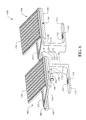
- FIG. 1 presents a top rear perspective view of a left-hand module of a portable interlocking solar energy and precipitation collection tower assembly in accordance with an implementation of the present invention
- FIG. 2 presents a rear elevation view of the left-hand tower module of FIG. 1 ;
- FIG. 3 presents a cross-sectional view of the left-hand tower module taken along section line 3 - 3 of FIG. 2 ;
- FIG. 4 presents a top rear perspective view of a right-hand module of a portable interlocking solar energy and precipitation collection tower assembly in accordance with an implementation of the present invention
- FIG. 5 presents a top rear perspective view of a left-hand tower module
- FIG. 6 presents a partially exploded front perspective view of a tower module assembly embodying the present invention wherein a left-hand tower module is mated to a right-hand tower module;
- FIG. 7 presents a top left-hand perspective view of the assembled modular tower assembly
- FIG. 8 presents a left elevation view of the assembled modular tower assembly
- FIG. 9 presents a top perspective view of an interlock pin for securing the left-hand support module to the right hand support module;
- FIG. 10 presents a cross-sectional elevation view of the modular tower assembly shown in FIG. 7 and taken along the line 10 - 10 , FIG. 7 ;
- FIG. 11 presents a partially exploded top perspective view of two modular towers for mating one to the other;
- FIG. 12 presents a top perspective view of the two modular towers shown in FIG. 11 mated one to the other;
- FIG. 13 presents a cross-sectional elevation view of the mated modular towers shown in FIG. 12 and taken along the line 13 - 13 , FIG. 12 ;
- FIG. 14 presents an elevation view of a modular tower assembly illustrating an optional interface for using some of the energy collected by the tower module to charge an electric vehicle parked beneath the modular tower;
- FIG. 15 presents a plurality of modular tower assemblies wherein an auxiliary solar assembly interconnects and extends between a right end of a first modular tower and a left end of a second modular tower;
- FIG. 16 presents a top right perspective view of a right-hand modular tower including optional features mounted thereto;
- FIG. 17 presents a top right perspective view of the portable interlocking modular tower system of the present invention connected to a local power grid.
- the word “exemplary” or “illustrative” means “serving as an example, instance, or illustration.” Any implementation described herein as “exemplary” or “illustrative” is not necessarily to be construed as preferred or advantageous over other implementations. All of the implementations described below are exemplary implementations provided to enable persons skilled in the art to make or use the embodiments of the disclosure and are not intended to limit the scope of the disclosure, which is defined by the claims.
- the structural innovation of the present invention will enable the solar power industry to put increasing amounts of underutilized space to use.
- Vast swaths of asphalt nationwide can be covered by modular towers fitted with photovoltaic panels that generate electricity—while also providing shade for parked vehicles.
- the tower modules can be used to easily cover virtually any desired area of the parking lot. They create very little resistance to wind, thereby creating integral stability even under windy weather conditions. They convert parking lots into solar power plants.
- a further benefit of the modular towers of the present invention is that they are adapted for collecting clean water from natural precipitation, such as from rainwater.
- Grid-connected photovoltaic power systems are power systems energized by photovoltaic (PV) panels that are connected to the utility grid.
- Grid-connected PV power systems consist of PV panels, Maximum Power Point Tracking (MPPT), solar inverters, power conditioning units and grid connection equipment.
- Photovoltaic (PV) modules are a packaged, connected assembly of solar cells, which are electrically connected and mounted on a supporting structure to create a solar panel. When conditions are right, the grid-connected PV system supplies excess power, beyond consumption by the connected load, to the utility grid.
- Solar energy gathered by PV solar panels, intended for delivery to a power grid must be conditioned, or processed for use, by a grid-connected inverter. The inverter sits between the solar array and the grid, draws energy from each, and may be a large stand-alone unit or may be a collection of small inverters, each physically attached to individual solar panels.
- the present invention is directed to solar and precipitation collecting modular assembly 100 ( FIGS. 6 and 7 ) having left-hand and right-hand tower modules 102 and 104 .
- the left-hand tower module 102 includes a support tower module 110 having a base (or support foot) 112 with a width sufficiently narrow to fit between the left and right wheels of a motor vehicle.
- base 112 can have a width such that the wheels of the motor vehicle can rest on the top surface of the base (not shown).
- the support tower module 110 also includes a vertical pedestal 118 and a solar power mount 130 .
- the vertical pedestal 118 has a bottom end affixed to one end of the base 112 .
- the solar panel mount 130 has one end thereof affixed to a top end of the pedestal 118 and is cantilevered over the base.
- the solar panel mount 130 is sized to shelter a motor vehicle thereunder with sufficient additional space to permit individuals to enter and egress the vehicle.
- the solar panel mount 130 has a solar panel mounting surface 132 extending about the periphery thereof wherein the solar panel mounting surface 132 is substantially planar.
- a central portion 134 is formed as a concave surface and defines at a low point thereof a drain hole 136 to facilitate the removal of rainwater, melted snow, etc.
- the solar panel mount 130 further includes at one edge flanking the pedestal 118 a downwardly depending tongue 144 extending the length of the solar panel mount 130 .
- a receiver 140 is mounted to an opposite edge of the solar panel mount 130 and defines a groove 142 extending the length thereof.
- the groove 142 is shaped and positioned to receive the tongue 144 of a like configured support module 110 .
- the tongue 144 is configured as a downwardly depending wedge with a concurrently shaped groove 142 in the receiver 140 to simplify the alignment of adjacent support modules 110 .
- the tongue 144 and the receiver 140 each define an interlock hole 146 therethrough such that interlock holes 146 are axially aligned one with the other.
- the pedestal 118 includes at least one and most preferably two fixed interlock pins 120 extending from a side opposite the base 112 and most preferably in vertical alignment one with the other.
- the fixed interlock pins 120 can include an interlock tab 122 extending downwardly at an end thereof.
- the pedestal 118 also defines a keyed interlock hole 124 therethrough which further defines a key slot 125 .
- the left-hand tower module 102 further includes a solar panel assembly 150 which includes a solar array 152 attached to a mounting frame 154 with a hinge 156 at one edge thereof.
- the solar array 152 comprises a plurality of solar cells 158 for converting sunlight to electricity in a manner known in the art.
- the mounting frame 154 is sized to mate with the solar panel mounting surface 132 on the solar panel mount 130 of the support module 110 .
- the manner of mounting thereof can be facilitated in any of a plurality of known mounting methods, all of which are contemplated herein.
- the solar array 152 is selectively pivotal to an angular orientation between a horizontal orientation and a vertical orientation to optimize maximum absorption of solar energy.
- each solar array 152 may be operationally interconnected with electrical contacts 114 , 116 for the optional delivery of electric power to a vehicle parked therein.
- the right-hand tower module 104 is substantially similar to the left-hand tower module 102 .
- the right-hand tower module 104 includes, as illustrated in FIG. 4 , a support module 111 having a base 112 , a pedestal 118 , and a solar panel mount 130 substantially as described above.
- the solar panel mount 130 includes a tongue 144 depending from one edge thereof and at and opposite edge includes a receiver 140 defining a groove 142 .
- the tongue 144 and the receiver 140 are positioned on opposite edges from the left-hand support module of FIG. 1 .
- the pedestal 118 defines interlock holes 121 in an equal number and position to the fixed interlock pins 120 of the support module 110 .
- the right-hand tower module 104 also includes the solar panel assembly 150 mounted to the solar panel mount 130 .
- the tower module assembly 100 includes a left-hand tower module 102 and a right-hand tower module 104 , which are arranged such that the pedestal of the left-hand module is joined to the pedestal of the right-hand module and wherein the respective bases 112 extend oppositely one from the other.
- the fixed interlock pins 120 of the left-hand tower module 102 are received in the holes 121 of the right-hand tower module 104 such that the respective pedestals 118 abut one another and are aligned therewith.
- the interlock tabs 122 of the fixed interlock pins 120 engage the pedestal 118 of the right-hand tower module 111 .
- an interlock pin 126 has a pin shank 127 , a pin key 128 at one end thereof, and a pin head 129 at an opposite end thereof.
- the interlock pin 126 is received in the interlock hole 124 in the respective pedestals 118 , and oriented such that the pin key 128 of the interlock pin 126 is received in the key slot 125 of the interlock hole 124 .
- the interlock pin 126 is rotated to lock the left-hand tower module 102 to the right-hand tower module 104 .
- a tower module assembly 100 is positioned for use.
- a motor vehicle 190 is illustrated on the left-hand side as approaching the tower assembly 100 .
- the primary function of the present invention is to collect solar energy for direct transfer to a neighboring utility grid (as further described below), as an optional side benefit of the novel tower structure, the wheels of an electrical vehicle 190 could centrally straddle the base 112 of the left-hand tower module 102 to align charging terminals 196 on the underside of the vehicle 190 with optional electrical contacts 114 , 116 on the base 112 .
- the vehicle 190 continues progressing forward until the vehicle charging terminals 196 have engaged electrical contacts 114 , 116 on the base 112 as illustrated on the right-hand side of FIG. 14 wherein the vehicle 190 is parked.
- the left-hand and right-hand tower modules 102 , 104 may include an electrical storage unit 106 interconnected with the solar panel assembly 150 and electrical contacts 114 , 116 for storage of electrical power generated when there is no vehicle engaged with the electrical contacts 114 , 116 .
- two or more tower module assemblies 100 can be ganged together in a laterally progressing sequence wherein the tongue 144 of a first modular tower assembly 100 is received in the groove 142 of a second modular tower assembly 100 .
- the interlock holes 146 of the engaged tongue 144 in the groove 142 of the receiver 140 of the inter joined modular tower assemblies 100 are aligned.
- An interlock pin 126 is inserted through the interlock holes 146 and rotated such that the pin key 128 locks the pin 126 in place in the manner as described above.
- two modular tower assemblies 100 can be arranged in-line and separated one from the other wherein a solar panel bridge 180 has one end thereof affixed to the free cantilevered end of a first modular tower assembly 100 and an opposite end thereof affixed to the free cantilevered end of a second modular tower assembly 100 .
- the solar panel bridge 180 includes one or more solar panel assemblies 150 attached to a top thereof and electrically interconnected with the modular tower assemblies 100 .
- the solar panel bridge 180 further includes a tongue such as tongue 144 and a groove such as groove 142 such that when interconnected with the modular tower assemblies 100 there is a continuous tongue along one edge thereof and a continuous groove along an opposite edge thereof.
- interconnected modular tower assemblies 100 and solar panel bridge 180 can be ganged together to provide plurality of modular towers and a drive area beneath the solar panel bridge 180 . This configuration is particularly useful for large parking areas.
- a left-hand modular tower 102 and a right-hand modular tower 104 can be separated one from the other and oriented such that a free cantilevered end of each solar panel mount of the respective modules 102 , 104 are facing one to the other.
- a solar panel bridge 180 has one end thereof affixed to the free cantilevered end of the left-hand module 102 and an opposite end thereof affixed to the free cantilevered end of the right-hand module 104 .
- This configuration provides additional solar panel assemblies for the generation of additional electrical power.
- this configuration can be laterally ganged together with other like assembled modules 102 , 104 and solar panel bridges 180 to provide additional power.
- the primary benefit of the portable tower module assembly of the present invention is that it provides a grid-connected photovoltaic power system, whereby energized photovoltaic (PV) panels are connected, for example by power lines 195 , to the utility grid 210 .
- Grid-connected PV power systems consist of PV panels, Maximum Power Point Tracking (MPPT), solar inverters, power conditioning units and grid connection equipment (generally referred to in FIG. 17 as reference numeral 198 ).
- PV Photovoltaic
- PV Photovoltaic
- the grid-connected PV system supplies excess power, beyond consumption by the connected load, to the utility grid.
- Solar energy gathered by PV solar panels, intended for delivery to a power grid must be conditioned, or processed for use, by a grid-connected inverter.
- the inverter sits between the solar array and the grid, draws energy from each, and may be a large stand-alone unit or may be a collection of small inverters, each physically attached to individual solar panels.
Abstract
Description
-
- a vertically-oriented pedestal portion having an upper end, a lower end, a left-facing surface and an opposite right-facing surface, the right-facing surface having at least one interlocking pin extending outwardly therefrom and a keyed interlock aperture extending therethrough;
- a horizontally-oriented support foot having an upper surface, a lower surface, a proximal end portion and a distal end, the pedestal portion lower end transitioning into said proximal end of said support foot;
- a solar panel mounting and precipitation collection portion having a periphery surrounding a concave upper surface, the concave upper surface having a precipitation drainage aperture extending therethrough, the pedestal portion upper end transitioning into said solar panel mounting and precipitation collection portion, the solar panel mounting and precipitation collection portion extending outwardly in a cantilevered manner over the support foot;
- a solar panel assembly mounted atop the support module solar panel mounting and precipitation collection portion; and
-
- a vertically-oriented pedestal portion having an upper end, a lower end, a left-facing surface and an opposite right-facing surface, the left-facing surface having at least one interlocking pin-receiving aperture sized and shaped for engagement with the corresponding at least one interlocking pin of said left-hand support module, and a keyed interlock aperture extending therethrough;
- a horizontally-oriented support foot having an upper surface, a lower surface, a proximal end portion and a distal end, the pedestal portion lower end transitioning into the proximal end portion of the support foot;
- a solar panel mounting and precipitation collection portion having a periphery surrounding a concave upper surface, the concave upper surface having a precipitation drainage aperture extending therethrough, the pedestal portion upper end transitioning into the solar panel mounting and precipitation collection portion, the solar panel mounting and precipitation collection portion extending outwardly in a cantilevered manner over the support foot; and
- a solar panel assembly mounted atop the support module solar panel mounting and precipitation collection portion.
Claims (17)
Priority Applications (1)
| Application Number | Priority Date | Filing Date | Title |
|---|---|---|---|
| US14/270,040 US8991117B1 (en) | 2014-05-05 | 2014-05-05 | Solar and rainwater tower |
Applications Claiming Priority (1)
| Application Number | Priority Date | Filing Date | Title |
|---|---|---|---|
| US14/270,040 US8991117B1 (en) | 2014-05-05 | 2014-05-05 | Solar and rainwater tower |
Publications (1)
| Publication Number | Publication Date |
|---|---|
| US8991117B1 true US8991117B1 (en) | 2015-03-31 |
Family
ID=52707709
Family Applications (1)
| Application Number | Title | Priority Date | Filing Date |
|---|---|---|---|
| US14/270,040 Active US8991117B1 (en) | 2014-05-05 | 2014-05-05 | Solar and rainwater tower |
Country Status (1)
| Country | Link |
|---|---|
| US (1) | US8991117B1 (en) |
Cited By (12)
| Publication number | Priority date | Publication date | Assignee | Title |
|---|---|---|---|---|
| WO2017134435A1 (en) * | 2016-02-03 | 2017-08-10 | Wendy Thomson | Modular solar-energy and rainwater collection apparatus |
| CN107386715A (en) * | 2017-08-31 | 2017-11-24 | 苏州天地彩钢制造有限公司 | A kind of color steel bicycle shed |
| US9831820B1 (en) * | 2016-05-13 | 2017-11-28 | Boson Robotics Ltd. | Moving mechanism and photovoltaic panel cleaning equipment having same |
| WO2020010360A1 (en) * | 2018-07-06 | 2020-01-09 | Kbfx Llc | Solar carports, solar-tracking carports, and methods |
| US10541640B2 (en) | 2017-07-07 | 2020-01-21 | Designer Direct, Inc. | Solar power system for marine dock |
| US10749462B2 (en) | 2017-12-30 | 2020-08-18 | studio [Ci] | Hybridized canopy |
| CN112324201A (en) * | 2020-09-22 | 2021-02-05 | 曹景 | Can collect and utilize new energy automobile parking shed of rainwater |
| US11063553B2 (en) | 2008-11-17 | 2021-07-13 | Kbfx Llc | Solar carports, solar-tracking carports, and methods |
| US20220074195A1 (en) * | 2018-11-19 | 2022-03-10 | Meta - Base Holdings Llc | Base for use with a temporary habitable enclosure or non-enclosed area |
| US11283393B2 (en) | 2008-11-17 | 2022-03-22 | Kbfx Llc | Movable building crown |
| WO2022173943A1 (en) * | 2021-02-10 | 2022-08-18 | Njie Mohammed Alboury | Poly-layered, poly-dimensional solar-stack structure |
| EP4068400A1 (en) * | 2021-04-01 | 2022-10-05 | Hamilton Sundstrand Corporation | Thermoelectric power generation using radiant and conductive heat dissipation |
Citations (9)
| Publication number | Priority date | Publication date | Assignee | Title |
|---|---|---|---|---|
| US4611090A (en) * | 1984-12-28 | 1986-09-09 | Standard Oil Company | Semirigid photovoltaic module assembly and structural support therefor |
| US8013569B2 (en) * | 2009-03-06 | 2011-09-06 | Sustainable Structures LLC | Renewable energy vehicle charging station |
| USD657735S1 (en) * | 2011-05-20 | 2012-04-17 | Solaire Generations, Inc. | Solar power generation assembly |
| US8375655B1 (en) * | 2011-08-19 | 2013-02-19 | Leopold Kostal Gmbh & Co. Kg | Carport for a motor vehicle |
| US8471141B2 (en) * | 2007-05-07 | 2013-06-25 | Nanosolar, Inc | Structures for low cost, reliable solar roofing |
| US8511007B2 (en) * | 2011-02-28 | 2013-08-20 | John Powers, III | Solar support structure |
| US8607512B2 (en) * | 2009-05-26 | 2013-12-17 | Art' ur SARL | Parking shelter provided with photovoltaic solar panels |
| US8640394B2 (en) * | 2010-02-22 | 2014-02-04 | Donald S. Richardson | Arcuate-winged solar canopy assembly |
| US20140196387A1 (en) * | 2010-08-26 | 2014-07-17 | Christopher Neito | Covered Parking Structure Adjustable Solar Energy Collector Holder and Parking Lot Thereof |
-
2014
- 2014-05-05 US US14/270,040 patent/US8991117B1/en active Active
Patent Citations (9)
| Publication number | Priority date | Publication date | Assignee | Title |
|---|---|---|---|---|
| US4611090A (en) * | 1984-12-28 | 1986-09-09 | Standard Oil Company | Semirigid photovoltaic module assembly and structural support therefor |
| US8471141B2 (en) * | 2007-05-07 | 2013-06-25 | Nanosolar, Inc | Structures for low cost, reliable solar roofing |
| US8013569B2 (en) * | 2009-03-06 | 2011-09-06 | Sustainable Structures LLC | Renewable energy vehicle charging station |
| US8607512B2 (en) * | 2009-05-26 | 2013-12-17 | Art' ur SARL | Parking shelter provided with photovoltaic solar panels |
| US8640394B2 (en) * | 2010-02-22 | 2014-02-04 | Donald S. Richardson | Arcuate-winged solar canopy assembly |
| US20140196387A1 (en) * | 2010-08-26 | 2014-07-17 | Christopher Neito | Covered Parking Structure Adjustable Solar Energy Collector Holder and Parking Lot Thereof |
| US8511007B2 (en) * | 2011-02-28 | 2013-08-20 | John Powers, III | Solar support structure |
| USD657735S1 (en) * | 2011-05-20 | 2012-04-17 | Solaire Generations, Inc. | Solar power generation assembly |
| US8375655B1 (en) * | 2011-08-19 | 2013-02-19 | Leopold Kostal Gmbh & Co. Kg | Carport for a motor vehicle |
Cited By (23)
| Publication number | Priority date | Publication date | Assignee | Title |
|---|---|---|---|---|
| US11063553B2 (en) | 2008-11-17 | 2021-07-13 | Kbfx Llc | Solar carports, solar-tracking carports, and methods |
| US11283393B2 (en) | 2008-11-17 | 2022-03-22 | Kbfx Llc | Movable building crown |
| US10627135B2 (en) * | 2016-02-03 | 2020-04-21 | Intuitive Designs (Jersey) Ltd | Modular solar-energy and rainwater collection apparatus |
| CN108779630A (en) * | 2016-02-03 | 2018-11-09 | 直觉设计(泽西)有限公司 | Modular solar power and rain collector |
| WO2017134435A1 (en) * | 2016-02-03 | 2017-08-10 | Wendy Thomson | Modular solar-energy and rainwater collection apparatus |
| US20190056149A1 (en) * | 2016-02-03 | 2019-02-21 | Intuitive Designs (Jersey) Ltd | Modular solar-energy and rainwater collection apparatus |
| GB2545938B (en) * | 2016-02-03 | 2018-12-12 | Intuitive Designs Jersey Ltd | Modular solar-energy and rainwater collection apparatus |
| US10016637B2 (en) * | 2016-05-13 | 2018-07-10 | Boson Robotics Ltd. | Anti-falling mechanism and photovoltaic panel cleaning equipment having same |
| US9831821B1 (en) * | 2016-05-13 | 2017-11-28 | Boson Robotics Ltd. | Correction mechanism and photovoltaic panel cleaning equipment having same |
| US10008976B2 (en) * | 2016-05-13 | 2018-06-26 | Boson Robotics Ltd. | Self-locking mechanism and photovoltaic panel cleaning equipment having same |
| US9831823B1 (en) * | 2016-05-13 | 2017-11-28 | Boson Robotics Ltd. | Obstacle crossing mechanism and photovoltaic panel cleaning equipment having same |
| US9831820B1 (en) * | 2016-05-13 | 2017-11-28 | Boson Robotics Ltd. | Moving mechanism and photovoltaic panel cleaning equipment having same |
| US10541640B2 (en) | 2017-07-07 | 2020-01-21 | Designer Direct, Inc. | Solar power system for marine dock |
| US10903781B2 (en) | 2017-07-07 | 2021-01-26 | Designer Direct, Inc. | Solar power system for marine dock |
| CN107386715A (en) * | 2017-08-31 | 2017-11-24 | 苏州天地彩钢制造有限公司 | A kind of color steel bicycle shed |
| US10749462B2 (en) | 2017-12-30 | 2020-08-18 | studio [Ci] | Hybridized canopy |
| WO2020010360A1 (en) * | 2018-07-06 | 2020-01-09 | Kbfx Llc | Solar carports, solar-tracking carports, and methods |
| US20220074195A1 (en) * | 2018-11-19 | 2022-03-10 | Meta - Base Holdings Llc | Base for use with a temporary habitable enclosure or non-enclosed area |
| CN112324201A (en) * | 2020-09-22 | 2021-02-05 | 曹景 | Can collect and utilize new energy automobile parking shed of rainwater |
| WO2022173943A1 (en) * | 2021-02-10 | 2022-08-18 | Njie Mohammed Alboury | Poly-layered, poly-dimensional solar-stack structure |
| US11837674B2 (en) | 2021-02-10 | 2023-12-05 | Mohammed Alboury Njie | Poly-layered, poly-dimensional solar-stack structure |
| EP4068400A1 (en) * | 2021-04-01 | 2022-10-05 | Hamilton Sundstrand Corporation | Thermoelectric power generation using radiant and conductive heat dissipation |
| US11777441B2 (en) | 2021-04-01 | 2023-10-03 | Hamilton Sundstrand Corporation | Thermoelectric power generation using radiant and conductive heat dissipation |
Similar Documents
| Publication | Publication Date | Title |
|---|---|---|
| US8991117B1 (en) | Solar and rainwater tower | |
| US8552581B2 (en) | Portable solar and wind-powered energy generating system | |
| CA2877885C (en) | Portable solar and wind-powered energy generating system | |
| Mouli et al. | Economic and CO2 emission benefits of a solar powered electric vehicle charging station for workplaces in the Netherlands | |
| US9561731B2 (en) | Structural bollard assembly for electric vehicle infrastructure | |
| US20120131866A1 (en) | Parking shelter provided with photovoltaic solar panels | |
| JP2003102104A (en) | Potable charging system unit for electric vehicle | |
| US11411526B2 (en) | Infrastructure energy generation system comprising photovoltaic structures | |
| US9716464B2 (en) | Solar panel mounting apparatus and system | |
| Zeman | Photovoltaic systems | |
| US20220263455A1 (en) | Solar Powered Charging Station | |
| US10868492B2 (en) | Solar panel mounting apparatus and system | |
| Ingersoll et al. | The 2.1 kW photovoltaic electric vehicle charging station in the city of Santa Monica, California | |
| CN212366909U (en) | Hydrogen-light complementary micro-grid system | |
| KR200441732Y1 (en) | Device for fixing the solar photovoltatic power generation module | |
| CN205081548U (en) | Solar charging pavilion | |
| CN205596057U (en) | Photovoltaic bicycle shed | |
| Mishra et al. | Solar trees: Shift from grey to green sky for future fuel pumps under clean/green energy: India | |
| Khoso et al. | The Development of Solar Powered Carport Canopies for the Charging Infrastructure of Electric Vehicles | |
| CN207160641U (en) | A kind of photovoltaic gallery electricity generation system | |
| CN111817420A (en) | Hydrogen-light complementary micro-grid system and control method thereof | |
| CN208834652U (en) | Outdoor advertising board | |
| KR20180046630A (en) | Device for fixing the solar photovoltatic power generation solar cell panel | |
| JP3178805U (en) | Solar power panel layout | |
| CN205596055U (en) | Intelligence photovoltaic integration bicycle shed |
Legal Events
| Date | Code | Title | Description |
|---|---|---|---|
| AS | Assignment |
Owner name: CLEAN & GREEN ENERGY INTERNATIONAL, LLC., FLORIDA Free format text: ASSIGNMENT OF ASSIGNORS INTEREST;ASSIGNORS:WALKER, DOROTHY M., DR.;MACH, STANLEY, MR.;REEL/FRAME:032923/0205 Effective date: 20140516 |
|
| AS | Assignment |
Owner name: SOLUR TERRA, INC., FLORIDA Free format text: ASSIGNMENT OF ASSIGNORS INTEREST;ASSIGNOR:CLEAN & GREEN ENERGY INTERNATIONAL, LLC.;REEL/FRAME:034840/0581 Effective date: 20150108 |
|
| STCF | Information on status: patent grant |
Free format text: PATENTED CASE |
|
| FEPP | Fee payment procedure |
Free format text: MAINTENANCE FEE REMINDER MAILED (ORIGINAL EVENT CODE: REM.); ENTITY STATUS OF PATENT OWNER: MICROENTITY |
|
| FEPP | Fee payment procedure |
Free format text: SURCHARGE FOR LATE PAYMENT, MICRO ENTITY (ORIGINAL EVENT CODE: M3554); ENTITY STATUS OF PATENT OWNER: MICROENTITY |
|
| MAFP | Maintenance fee payment |
Free format text: PAYMENT OF MAINTENANCE FEE, 4TH YEAR, MICRO ENTITY (ORIGINAL EVENT CODE: M3551); ENTITY STATUS OF PATENT OWNER: MICROENTITY Year of fee payment: 4 |
|
| MAFP | Maintenance fee payment |
Free format text: PAYMENT OF MAINTENANCE FEE, 8TH YEAR, MICRO ENTITY (ORIGINAL EVENT CODE: M3552); ENTITY STATUS OF PATENT OWNER: MICROENTITY Year of fee payment: 8 |
|
| FEPP | Fee payment procedure |
Free format text: PETITION RELATED TO MAINTENANCE FEES GRANTED (ORIGINAL EVENT CODE: PTGR); ENTITY STATUS OF PATENT OWNER: MICROENTITY |