US8972837B2 - Read/write operations in solid-state storage devices - Google Patents
Read/write operations in solid-state storage devices Download PDFInfo
- Publication number
- US8972837B2 US8972837B2 US13/716,661 US201213716661A US8972837B2 US 8972837 B2 US8972837 B2 US 8972837B2 US 201213716661 A US201213716661 A US 201213716661A US 8972837 B2 US8972837 B2 US 8972837B2
- Authority
- US
- United States
- Prior art keywords
- symbols
- codewords
- codeword
- symbol
- code
- Prior art date
- Legal status (The legal status is an assumption and is not a legal conclusion. Google has not performed a legal analysis and makes no representation as to the accuracy of the status listed.)
- Expired - Fee Related, expires
Links
Images
Classifications
-
- G—PHYSICS
- G06—COMPUTING OR CALCULATING; COUNTING
- G06F—ELECTRIC DIGITAL DATA PROCESSING
- G06F11/00—Error detection; Error correction; Monitoring
- G06F11/07—Responding to the occurrence of a fault, e.g. fault tolerance
- G06F11/08—Error detection or correction by redundancy in data representation, e.g. by using checking codes
- G06F11/10—Adding special bits or symbols to the coded information, e.g. parity check, casting out 9's or 11's
- G06F11/1008—Adding special bits or symbols to the coded information, e.g. parity check, casting out 9's or 11's in individual solid state devices
- G06F11/1072—Adding special bits or symbols to the coded information, e.g. parity check, casting out 9's or 11's in individual solid state devices in multilevel memories
-
- G—PHYSICS
- G06—COMPUTING OR CALCULATING; COUNTING
- G06F—ELECTRIC DIGITAL DATA PROCESSING
- G06F11/00—Error detection; Error correction; Monitoring
- G06F11/07—Responding to the occurrence of a fault, e.g. fault tolerance
- G06F11/08—Error detection or correction by redundancy in data representation, e.g. by using checking codes
- G06F11/10—Adding special bits or symbols to the coded information, e.g. parity check, casting out 9's or 11's
- G06F11/1008—Adding special bits or symbols to the coded information, e.g. parity check, casting out 9's or 11's in individual solid state devices
- G06F11/1012—Adding special bits or symbols to the coded information, e.g. parity check, casting out 9's or 11's in individual solid state devices using codes or arrangements adapted for a specific type of error
- G06F11/1032—Simple parity
Definitions
- This invention relates generally to read/write operations in solid-state storage devices (SSSDs) and, more particularly, to methods and apparatus for reading and writing data in multi-level cells of solid-state memory.
- SSSDs solid-state storage devices
- the fundamental storage unit (the “cell”) can be set to a number of different states, or “levels”, which exhibit different electrical characteristics. These different levels can be used to store information. To readout stored information, cell-level is detected via measurements which exploit the differing electrical characteristics to differentiate between different levels.
- SLC single-level cell
- the memory cells can be set to only two levels and so can record only binary values.
- Other devices have so-called “multi-level cells” which can be set to q different levels, where q>2.
- Multi-level NOR flash memories for instance, can store 4 levels, i.e. 2 bits, per cell.
- Multi-level cell (MLC) NAND flash memory chips that can store 3 bits of data per single flash cell using 25 nm process technology are currently available. Storage of 2 bits per cell in PCM chips has also been demonstrated.
- each cell When writing information to multi-level cells, each cell can be used to store a q-ary symbol with each of the q possible symbol values being represented by a different cell level.
- the read signal level On readout of multi-level cells, the read signal level is compared with a set of reference signal levels indicative of the q cell-levels in order to determine which level each cell is set to and thus detect the stored symbol value.
- a problem in multi-level SSSDs is that the physical quantity measured during cell readout, such as electrical resistance in PCM devices, is liable to drift.
- the electrical resistance of PCM cells drifts upwards with time in a stochastic manner. This drift can be data-dependent, i.e. may vary for different cell levels.
- the physical quantity measured is the transistor's threshold voltage, and this drifts upwards as a function of the number of write/erase cycles the cell is subjected to. For any given stored symbol value and hence cell level, therefore, the actual read signal level obtained on cell-readout is variable.
- Drift is a serious problem for multi-level storage in that it severely compromises reliability.
- the readback values of neighboring levels may interfere over time, due to upward drift of the lower level towards the upper level, causing a detection error.
- packing higher numbers of levels per memory cell becomes more difficult due to the increased likelihood of error during cell-state detection.
- packing more bits per cell is a crucial requirement for all memory technologies, being the best known way of reducing manufacturing cost per bit.
- a few techniques have been proposed to tackle the problem of drift, but most remain at the academic interest level.
- One proposal is to use a certain part of the memory cell array as a reference pool of cells. These cells are written with known signal levels, and are continuously monitored during device operation, to obtain estimates of drift. The estimated drift values can then be used to update the reference levels used for level detection on readback.
- drift is a statistical phenomenon and there is significant variability between cells in the array, so reference cells may not be representative and the effectiveness of the proposed reference-cell based approaches will vary substantially over time and over different portions of the memory array.
- Model-based drift cancellation techniques seek to model drift based on key parameters such as temperature, time and wear, and compensate accordingly. It is, however, difficult to obtain an accurate cell history for the key parameters. There are also fluctuations from cell to cell and there is no well-established analytical model available for short-term drift.
- rank modulation has been proposed to address endurance problems and overshoot errors in flash memories (see “Rank Modulation for Flash Memories”, Jiang et al., IEEE Trans. Inf. Theory, vol. 55, no. 6, June 2009; and US Patent Application Publications No's. 2009/0132895A1 and 2009/0132758A1). While rank modulation may offer some drift benefits, it has two severe drawbacks, namely: (i) it offers only low code rate for a given number of levels; and (ii) it lacks an efficient mapping of data bits into codewords. Hence, rank modulation does not provide a practical solution and is mostly of theoretical interest.
- This technique encodes input data as N-symbol codewords of a so-called “translation-stable code”.
- Each codeword symbol can take one of q symbol values and is recorded in a respective q-level cell by setting the cell to a level dependent on the q-ary symbol value.
- the translation-stable code is such that each possible input data word is mapped by the coding scheme to a codeword with a unique sequence of relative symbol values.
- Such a code can be constructed from codewords in a set of one or more permutation codes.
- Each codeword of a permutation code is a particular permutation of a predefined vector (the “initial vector”) which has N q-ary symbols arranged in order of increasing symbol value. Detection of codewords on readback can be performed by relating the read signals for codewords to the initial vectors for the code.
- a translation-stable code With a translation-stable code, information is effectively encoded in the relative, as opposed to the absolute, read signal component levels. This feature obviates primary effects of drift on detection accuracy, whereby translation-stable codes can be considered effectively drift-invariant.
- Translation-stable codes also offer higher code rates than rank modulation schemes for a given number of levels.
- Components of these ordered read signals are related to symbols of the known set of initial vectors via a process which involves averaging ordered read signals and relating the average components to symbol values using predefined probabilities of occurrence of different symbol values at different symbol positions as derived from the initial vectors.
- reliable estimates can be obtained for the reference signal levels for the q-level cells in the current batch.
- These reference levels can then be used in codeword detection for the current batch.
- This self-adaptive technique thus uses the actual cells storing encoded data to estimate the reference levels for those cells on readback, thereby accounting for drift effects on a dynamic basis.
- the technique is also robust and lends itself to simple, fast decoder implementation. Good, practical encoding schemes for use in such systems nonetheless remain a matter for case-by-case study.
- An embodiment of one aspect of the present invention provides a method for reading and writing data in q-level cells of solid-state memory, where q>2.
- the method comprises:
- Methods embodying this invention encode data for storage in multilevel cells using length-N, q ary -symbol codes in which the symbols of each codeword satisfy a single-parity-check (SPC) condition.
- SPC single-parity-check
- the SPC condition may apply to the symbols as a whole or to sub-symbols thereof as discussed further below.
- Methods embodying the invention are predicated on the realization that, because the result of a single parity check is invariant under permutation of its arguments, the codewords of such SPC-based codes are all permutations of an identifiable set of N-symbol vectors (where this set of vectors may in general contain one or more vectors). This permutation feature can be exploited to enable codeword detection.
- SPC-based codes provide good, high-rate codes with large minimum distance.
- This in conjunction with efficient permutation-based decoding, offers excellent performance in read/write systems embodying the invention.
- many SPC-based codes have simple encoders with efficient mapping of data bits into codewords. This can be exploited in preferred embodiments for exceptionally efficient implementations.
- the ability to use SPC-based codes in multilevel SSSDs by exploiting the permutation property for decoding offers a systematic approach to the construction of high-rate codes for multilevel SSSDs with simple encoding of user data and good trade-off between gains in minimum distance and rate loss.
- SPC-based codes allow drift-resistant techniques to be implemented as discussed earlier.
- the read-detection technique of EP 11183336.4 referenced above can be employed in embodiments of the invention.
- Particularly preferred embodiments employ SPC-based codes which are also translation-stable and hence drift-invariant. Overall, therefore, methods embodying the invention offer very significant advantages in multilevel-cell storage devices.
- the single-parity-check condition which the symbols of each codeword satisfy may be that the q ary symbols as a whole, or sub-symbols of these q ary symbols, satisfy a single-parity-check equation.
- the SPC-based code may be a single-level code in some embodiments.
- the codewords may, for example, be codewords of a length-N SPC code.
- the codewords may be codewords of a coset of such an SPC code.
- the SPC-based code may be a multilevel code whereby the codeword symbols each comprise a plurality of sub-symbols corresponding to respective code levels.
- the N sub-symbols of at least one code level may comply with one of a length-N SPC code or a coset thereof. That is, for at least one code level, each group of N sub-symbols forms a codeword of an SPC code (or coset).
- SPC-based codes will be given below. With all such codes, preferred embodiments can take advantage of the SPC-based code to perform simple and efficient encoding of input user data. This is discussed further below.
- the set of possible (i.e. permitted or “valid”) codewords used in the system need not necessarily include all codewords encompassed by the SPC-based code in question.
- some embodiments may employ a limited codeword set obtained from a reduced set of basic vectors from which one or more vectors has been eliminated. This is explained in detail below. While this increases encoder complexity, it may be desirable in some embodiments as the reduced vector set simplifies decoding and so may enhance error performance.
- the permutation property of the SPC-based codes is exploited for detection purposes by relating the read signals for codewords to the set of vectors of which all codewords are permutations.
- the particular detection process, and the particular way in which read signals are related to the set of basic vectors during this process, can vary in different embodiments, e.g. depending on the particular SPC-based code employed.
- the detection process typically involves an ordering of the components of read signals. Specifically, each read signal may comprise N signal components corresponding to respective symbols of a codeword. The components of each read signal are ordered according to signal level to produce an ordered read signal. The components of ordered read signals are then related to symbols of the set of vectors during detection. The details of this process may depend on the particular code, e.g.
- the relating of read signal components to vector symbols may be performed via an averaging process over a group of ordered read signals, generally as in the permutation-based detection system of EP11183336.4 referenced above.
- the average components can be related to corresponding symbols in the basic vectors, using the aforementioned probabilities, to derive estimates for the reference signal levels for the q cell-levels.
- the process can also involve one or more further stage(s) of relating ordered read signals to basic vectors, e.g. via a clustering process, and/or a trellis decoding stage. Detection techniques for various scenarios will be described in more detail below.
- An embodiment of a second aspect of the invention provides apparatus for reading and writing data in q-level cells of solid-state memory, where q>2.
- the apparatus comprises:
- an encoder for encoding input data into codewords having N q ary symbols, wherein the symbols of each codeword satisfy a single-parity-check condition
- a read/write controller for writing each symbol in a respective cell of the solid state memory by setting the cell to a level dependent on the q ary value of the symbol, and for reading memory cells to obtain read signals corresponding to respective codewords;
- a detector for detecting the codewords corresponding to respective read signals by relating the read signals to a predetermined set of N-symbol vectors of one of which each possible codeword is a permutation.
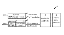
- FIG. 1 is a schematic block diagram of a solid-state storage device embodying the invention
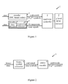
- FIG. 2 shows a generalized encoder for the FIG. 1 device
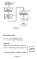
- FIG. 3 indicates key steps in operation of an exemplary codeword detector in the FIG. 1 device
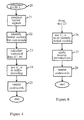
- FIG. 4 indicates further steps of a first codeword detection method
- FIG. 5 shows an exemplary trellis diagram for use in the method of FIG. 4 ;
- FIG. 6 indicates steps of a second codeword detection method
- FIG. 7 illustrates construction of a simple translation-stable code
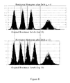
- FIG. 8 illustrates drift in relation to nominal resistance levels for 4-level and 5-level PCM cells.
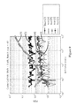
- FIG. 9 compares error performance of an embodiment of the invention and an uncoded scheme with various detection methods.
- FIG. 1 is a simplified schematic of a solid-state storage device, here a phase-change memory (PCM) device 1 , embodying the invention.
- the device 1 includes phase-change memory 2 for storing data in one or more integrated arrays of multilevel PCM cells. Though shown as a single block in the figure, in general memory 2 may comprise any desired configuration of PCM storage units ranging, for example, from a single chip or die to a plurality of storage banks each containing multiple packages of storage chips.
- Device 1 includes an encoder 3 for encoding input data in accordance with an SPC-based encoding scheme discussed further below.
- a read/write controller 4 controls writing of codewords in memory 2 and subsequent reading of memory cells to obtain read signals corresponding to codewords.
- a decoder 5 for processing the read signals comprises a codeword detector 6 , which detects codewords corresponding to the received read signals, and a data decoder 7 which decodes the codewords to recover the original user data.
- Each of the PCM cells in memory 2 can be set to one of q>2 nominal levels designated I 0 to I q-1 herein.
- Read/write controller 4 can set a cell to a particular level by adjusting the resistance of the cell in known manner. To read a cell, controller 4 applies a small probing signal to obtain a readback signal indicative of the cell's resistance. During write and read operations, controller 4 addresses individual cells in known manner by applying appropriate voltage signals to an array of word and bit lines in memory ensemble 2 .
- the input data to be recorded in memory 2 is supplied to encoder 3 .
- the symbols of a codeword can each take one of q possible values (s n ⁇ ⁇ 0, 1, . . . , q ⁇ 1 ⁇ ).
- the q possible symbol values correspond to respective predetermined levels I 0 to I q-1 of the q-level cells in memory 2 .
- a direct correspondence between symbol values 0, 1, . . . , q ⁇ 1 and cell levels I 0 to I q-1 is assumed for simplicity.
- Controller 4 stores the N symbols of each codeword output by encoder 3 in respective cells of memory 2 by setting each cell to a level dependent on the symbol value to be stored in accordance with the predefined correspondence between symbol values and cell levels. (Note that, when setting a cell to a given level, the actual resistance value x assumed by the cell may lie within a small interval around the nominal resistance value/for the level due to write noise).
- Encoder 3 implements an SPC-based code such that the N symbols of each codeword satisfy a parity condition.
- the SPC-based code may in general be a single-level code or a multi-level code.
- FIG. 2 is a schematic illustration, in generalized form, of a simple encoder for use in preferred embodiments of device 1 .
- the encoder 3 is implemented here by a binary symbol converter 8 and a parity encoder 9 .
- the binary symbol converter 8 maps binary input data symbols into converted data symbols in which the binary data is represented in a different alphabet or alphabets. For single-level codes, the data conversion is performed directly from binary to q-ary data symbols.
- Binary symbol converter 8 For multi-level codes, binary data is mapped to groups of “sub-symbols”, with respective “sub-alphabets”, which in combination represent a q-ary value. This is explained further below.
- Binary symbol converter 8 thus performs a simple data mapping operation, involving no SPC-based coding.
- the converted data symbols are then output to parity encoder 9 which encodes successive groups of data symbols into length-N r-symbol codewords whose symbols satisfy the parity condition for the code in question.
- the encoding involves a simple addition of parity symbols to converted data symbols as discussed further below.
- the symbol converter 8 can be implemented for preference using hard-wired logic gates or, for example, using a look-up table for the alphabet conversion.
- parity encoder 9 can also be implemented in a simple manner using hard-wired logic gates. Suitable implementations will be readily apparent to those skilled in the art from the description herein.
- Data decoder 7 can be constructed in corresponding manner to perform the inverse of the encoding operation in encoder 3 .
- the SPC-based code used in encoder 3 may be a length-N single-parity-check code or a coset of such a code. These are single-level codes.
- the symbol converter 8 maps binary input data into successive groups of (N ⁇ 1) q ary data symbols. This mapping of binary to q ary symbols can be achieved in known manner. If q is a power of 2 then the mapping is trivial. Otherwise the mapping can be achieved by performing a base change (i.e. a data conversion) from a binary to a q ary alphabet.
- parity encoder 9 then simply encodes each group of (N ⁇ 1) q ary data symbols into a respective N-symbol codeword by adding a q ary parity symbol so as to satisfy the parity-check equation above.
- parity encoder 9 which are output to parity encoder 9 .
- the parity encoder is implemented as a simple rate-8/9 encoder which maps 5 ary data symbols into codewords according to the linear mapping: ( c 1 ,c 2 , . . . , c 8 ) ⁇ ( c 1 ,c 2 , . . . , c 8 , ⁇ ( c 1 +c 2 + . . . +c 8 )).
- This code is particularly advantageous in that it is also a translation-stable code. This is discussed further below.
- the SPC-based code used in encoder 3 may be a multi-level code.
- the codeword symbols each comprise a group of sub-symbols which correspond to respective code levels.
- the SPC condition can be imposed here in that the N sub-symbols of at least one code level form a codeword of a length-N SPC code or coset thereof. Two such codes which can be employed in encoder 3 are described in the following.
- the code has a multi-level construction with first and second code levels whose sub-symbols correspond to the most-significant bit (MSB) and least significant bit (LSB) respectively of the 2-bit symbols defined by the labeling scheme.
- MSB most-significant bit
- LSB least significant bit
- the cell-levels that differ in the MSB only of the corresponding symbol value are 0 and 2, and 1 and 3. In both cases the distance between these levels is two.
- a code with a squared minimum distance of 2 can be obtained by imposing a single-parity constraint on the sub-symbols of the second code level, i.e. the LSBs, only.
- the data conversion required in symbol converter 8 of FIG. 2 is a trivial operation of mapping input bits to sub-symbols c′ 1 to c′ 8 and c′′ 1 to c′′ 7 .
- Parity encoder 9 then performs simple encoding of the resulting 15-bits into a length-8 codeword (c′ 1 c′′ 1 , c′ 2 c′′ 2 , . . . , c′ 8 c′′ 8 ) by adding parity bit c′′ 8 .
- the second multi-level code is another two-level code of length-8 and is similar to the code just described except that a single-parity constraint is imposed on both code levels.
- both the eight LSBs and the eight MSBs comply with a length-8 SPC code (or coset).
- the codeword construction is again given by ( c′ 1 c′′ 1 ,c′ 2 ,c′′ 2 , . . . , c′ 8 c′′ 8 ) where: in level 1, seven data bits c′ 1 to c′ 7 determine the parity bit c′ 8 ; and in level 2, seven data bits c′′ 1 to c′′ 7 determine the parity bit c′′ 8 .
- Parity encoder 9 then performs simple linear encoding of these fourteen bits into a length-8, 4 ary codeword by calculating and adding the parity bits c′ 8 c′′ 8 as the final codeword symbol.
- the code rate is lower due to parity coding of both code levels, the resulting code has a smaller set of initial vectors which are exploited in the decoding process discussed below. This reduces the likelihood of error in the decoding process, offering improved accuracy on readback.
- encoder 3 maps binary data to groups of sub-symbols, with respective sub-alphabets, which in combination represent a q ary value.
- a single-parity constraint can be imposed on one or more of the different code levels. For any code level having a parity constraint, encoder 3 encodes groups of (N ⁇ 1) sub-symbols of that code level into the N sub-symbols of that level in respective codewords of the overall SPC-based code.
- the above parity-based codes offer high-rate codes with good minimum distances and can be implemented in a simple manner using a base change and simple linear encoding.
- the codes thus provide a simple mapping of input data to codewords and simple encoder construction.
- consideration of these SPC-based codes shows that the codes are invariant under permutation of their arguments, the parity condition being satisfied for all permutations of the symbol set (c 1 , c 2 , . . . , c N ). It follows that all codewords of such a code are permutations of an identifiable subset of the codewords.
- This subset constitutes a set of N-symbol vectors for the code such that each possible codeword is a permutation of one vector in the set.
- these codes can be viewed as a union of permutation codes.
- a permutation code is characterized by a real vector of length-N (the “initial vector”) on which the permutation group of N letters operates.
- the code is completely determined by its length-N and the initial vector X 0 which has N components (symbols).
- the codewords consist of all length-N vectors that are obtained through a permutation of the components of the initial vector.
- the SPC-based codes described above can be viewed as a union of length-N permutation codes, whereby each possible codeword is a permutation of one of a set of N-symbol vectors being the set of initial vectors of the permutation codes.
- the permutation property of the SPC-based codes described herein provides the basis for efficient decoding of these codes.
- the read signals obtained for codewords on readback can be related to the predetermined set of N-symbol vectors for the code as the basis of the codeword detection process.
- the relating of read signals to vectors can be performed in a variety of ways depending on the particular code employed and the overall detection process in which is it used. Examples of preferred detection techniques are described in the following. These are based on the drift-resistant techniques described in our European Patent Application no. 11183336.4, referenced above, the relevant content of which is incorporated herein by reference.
- the detection methods to be described are performed by codeword detector 6 of device 1 .
- the codeword detector comprises control logic for implementing the various steps of the codeword detection process, and this control logic may be embodied in hardware or software or a combination of hardware and software components. Suitable implementations will be readily apparent to those skilled in the art from the description of operation herein.
- blocks of codewords are written/read substantially simultaneously to memory 2 by read/write controller 4 .
- the read signals y are supplied to codeword detector 6 .
- the signal components y 1 , . . . y N of each read signal correspond to respective symbols S 1 , . . . s N of a stored codeword.
- the read-back resistance levels y corresponding to a given symbol value s are variable due to drift and noise effects.
- codeword detector 6 For accurate detection of codewords from read signals y, codeword detector 6 must account for the variable resistance level distributions. Most fundamentally, the codeword detector requires estimates for the reference signal levels which correspond to the different cell levels I 0 to I q-1 , and hence to the different symbol values, for the read operation. These reference signal levels can then be used for codeword detection. An overview of the codeword detection process is given below with reference to the flow diagram of FIG. 3 .
- encoder 3 employs an SPC-based code which is a union of L permutation codes defined by the set of L initial vectors c (1) , c (2) , c (L) , each of length N, whose symbols are ordered in order of increasing symbol value.
- FIG. 3 indicates the main operational steps performed by codeword detector 6 .
- detector operation commences on receipt of a group of B read signals y from controller 4 corresponding to a group of B codewords read from memory 2 .
- the read signals y are temporarily stored in codeword detector 6 for use in the subsequent processing operation.
- the control logic of detector 6 orders the components y 1 to y N of each read signal y according to signal level.
- This ordering process defines a permutation (k 1 to k N ) of the signal components for each read signal y.
- the resulting ordered read signals are stored in codeword detector 6 .
- the detector logic averages corresponding components of the ordered read signals to obtain an “average” read signal 5 , at time t:
- the detector logic determines a current reference signal level ⁇ corresponding to each of the q levels of the memory cells.
- the corresponding drifted levels at time t are denoted by ⁇ 0 to ⁇ g-1 .
- X 0 [X k1 ,X k2 , . . . , X kN ] with X k1 ⁇ X k2 ⁇ . . . ⁇ X kN
- Such a matrix can be defined for any code C based on the known code structure, i.e. the set of valid codewords for the code. This will be illustrated by example below.
- Equation (4) represents an over-determined system of N linear equations which can be solved in known manner for the q unknowns ⁇ 0 , ⁇ 2 , . . . , ⁇ q-1 ⁇ .
- the probabilities defining the probability matrix P described above depend on the structure of the initial vectors and the number # ⁇ (c (j) ) of codewords which are permutations of each vector.
- the matrix P is thus defined by the probabilities of occurrence of the initial vectors and the symbol values at each symbol position in the initial vectors.
- relating the symbol values 0 to 3 in the initial vectors above to reference levels ⁇ 0 to ⁇ 3 via equation (6) gives:
- this set of linear equations can be solved in known manner for the unknown reference levels ⁇ 0 , . . . , ⁇ 3 .
- detector 6 solves the equations using a least-squares method as is well known to those skilled in the art.
- the ordered read signals for codewords are related to symbols of the set of initial vectors via an averaging process over a group of ordered read signals using the predefined probabilities of occurrence of each symbol value at each symbol position in a said codeword whose symbols are ordered according to symbol value. These probabilities depend on the values of symbols of the initial vectors at positions corresponding to respective components of the average read signal, and thus inherently involve relating the ordered read signal components to initial vectors as described above. This relation is used to obtain estimates of the reference levels from the ordered averaged read signals. The resulting estimates for the reference signal levels ⁇ 0 , . . . , ⁇ 3 for the q cell-levels can then be used to detect the current batch of codewords.
- the reference signal levels ⁇ 0 to ⁇ 3 could be used directly for codeword detection by comparing the components y n of each read signal y with these levels to identify the particular cell level, and hence symbol value, to which each read signal component corresponds.
- preferred embodiments offer improved detection accuracy by using the reference signal levels ⁇ 0 to ⁇ 3 to identify the initial vector of which the codeword corresponding to each read signal is a permutation.
- the read signals are divided into clusters, each cluster containing read signals representing codewords which are permutations of the same initial vector. Examples of such techniques will now be described with reference to FIGS. 4 and 5 .
- FIG. 4 shows the main steps of a first detection process which can be performed by codeword detector 6 .
- the operation commences at step 20 with determination of the current reference signal levels ⁇ 0 to ⁇ q-1 as already described.
- the resulting vector signals u(j) are then used to divide the group of B ordered read signals z i (from step 11 of FIG. 3 ) into clusters corresponding to respective initial vectors c (j) .
- ⁇ , where j 1, . . . , L.
- the minimum can be assessed here using any convenient minimum distance criterion, e.g. using a simple Euclidean distance metric.
- the detector logic calculates statistical data for the distribution of the read signal component levels corresponding to each of the q nominal levels of the memory cells.
- the read signal level distributions for each of the q cell-levels are obtained. These distributions are then processed to obtain the means and variances in each case.
- the mean values so obtained for the q cell-levels are denoted by ⁇ ′ 0 to ⁇ ′ 0 and represent updated values for the reference signal levels ⁇ used in initial clustering step 22 .
- the variances for each level distribution are denoted by ⁇ .
- the detector logic uses the means ⁇ ′ and variances a in a trellis decoding operation.
- Trellis decoding is well known in the art and need not be described in detail here. Suffice to say that, for a single parity check on an r-level alphabet in an SPC-based code described herein, detection via a MAP (maximum-a-posteriori) method or a ML (maximum-likelihood) method can be efficiently implemented by a trellis with at most r states.
- 2-state trellis for the first two-level code described above, with parity coding on the least-significant bit is shown in FIG. 5 .
- the second two-level code, with parity coding on both the LSB and MSB can be decoded using a 4-state trellis.
- An appropriate trellis diagram for any given parity code will be apparent to those skilled in the art.
- the codeword detected in step 24 for each of the group of B read signals is then output by codeword detector 6 in step 25 of FIG. 4 .
- detector 6 simply outputs an erasure symbol for that codeword. This can be addressed by some suitable error-correction processing in data decoder 7 . Such processes are well known to those skilled in the art and need not be addressed here).
- the codeword detection process is then complete.
- FIG. 6 indicates a modification to the FIG. 4 technique.
- This uses permutation-based detection instead of the trellis decoding step of FIG. 4 .
- the process of ordering read signals defines a permutation (k 1 to k N ) of the signal components for each read signal y.
- This permutation is used in the detection method of FIG. 6 .
- the FIG. 6 method commences with steps 20 to 23 of FIG. 4 as before. In step 26 , however, the detector logic uses the means 80 ′ and variances ⁇ in a second pass of the clustering operation initially performed in step 22 .
- the initial vector to which each ordered reads signal corresponds is again identified, this time using the statistical data ( ⁇ ′, ⁇ ) for the level distributions.
- This process is preferably based on one of MAP and ML detection, such methods being well known to those skilled in the art.
- the closest initial vector c (r) for each ordered read signal z i is identified as:
- ⁇ n ( ⁇ ) corresponds to initial vector c (v) with symbols replaced by the corresponding mean reference levels ⁇ ′;
- ⁇ n ( ⁇ ) represents the standard deviation of the distribution for the reference level with mean ⁇ ′ which corresponds to each component of ⁇ n ( ⁇ ) .
- the detector logic can detect the codeword corresponding to each read signal by applying an inverse permutation to the initial vector identified for the read signal.
- the inverse permutation is simply the inverse of the permutation (k 1 to k N ) of that read signal which produced the ordered read signal via (1) above.
- the resulting codeword for each read signal (or an erasure signal if no valid codeword is detected) is then output in step 28 , and the process is complete.
- SPC-based codes exploit the permutation property of SPC-based codes to achieve efficient, drift-resistant decoding in device 1 .
- the detection process is independent of underlying drift characteristics (as long as drift does not reorder the resistance levels), and also accounts for data-dependent noise whereby different cell-levels are subject to differing noise effects.
- some SPC-based codes are also translation-stable codes and as such are fundamentally drift-invariant.
- Translation-stable codes are defined and described in US 2011/0296274A1, mentioned earlier, the relevant content of which is incorporated herein by reference. Briefly, however, with a translation-stable encoding scheme, each data word in the set of all possible input data words is encoded as a codeword with a unique sequence of relative symbol values.
- the initial vector X 0 in this example is as shown in the figure.
- the set of codewords ⁇ c ⁇ for the code C consists of all possible permutations of the initial vector X 0 as indicated in the figure.
- Inherent in this code is that each of these codewords has a unique sequence of symbol values relative to the lowest symbol value in the codeword, whereby adding any real-valued number to all symbol values in a codeword does not result in another codeword.
- the translation vector t [1 1 1 . . .
- all potential codewords of the SPC-based code i.e. all N-symbol words satisfying the necessary parity constraint, are exploited in the code. This is not, however, essential. In some applications it may be preferable to use a limited set of codewords.
- this limited codeword set may exclude length-N q ary symbol words whose symbols satisfy the SPC condition but which are contained in the set of all permutations of at least one N-symbol vector having a smaller orbit under permutation than vectors in said predetermined set. That is, starting with the set of initial vectors for the “complete” code, one or more vectors which have the smallest orbit under permutation are eliminated.
- the encoder 3 must perform coding by mapping input data into the remaining codewords. This could be implemented, for example, by using a look-up table, in particular for small codes, or using the well-known technique of enumerative source coding for more efficient operation with large codes. Decoding of this type of code can be performed, for example, using the detection process of FIG. 6 . In any case, by eliminating initial vectors as described, there are fewer initial vectors to be considered during detection whereby detection performance may be enhanced. Simulation results indicate that such “reduced codes” perform well even small batch sizes B.
- Performance results for an exemplary SPC-based code are discussed below in connection with FIGS. 8 and 9 .
- the code considered here is the length-9 translation-stable SPC code described above.
- the nominal programmed cell-levels in the upper histogram are [4.0, 4.5, 5.0, 6.0] in logR.
- the standard deviation of noise per level is [1, 1, 1, 3] ⁇ 6.
- the trace labeled [1] corresponds to the SPC code with trellis or permutation-based decoding as in FIG. 4 or 6 above.
- Trace [2] is the equivalent result for the uncoded case with permutation-based decoding.
- Trace [3] is for the SPC code but using a genie (i.e. an impractical detector that has perfect knowledge of all memory cell data and hence drift) to perform a model-based correction for drift.
- Trace [4] is the equivalent result for the uncoded scheme with genie-aided detection.
- trace [5] shows the result for the SPC code but using the original, nominal reference levels/at time zero in decoding. It is apparent from this figure that the 5-level SPC scheme outperforms the 4-level uncoded scheme with equivalent detection methods. The coded scheme is more robust against data-dependent noise and its performance is significantly closer to the genie-aided performance than the uncoded scheme.
- embodiments of the invention provide significant improvements in multilevel solid-state storage devices.
- SPC-based codes offers a systematic approach to the construction of high-rate codes with simple encoding of user data, which provide a good trade-off between minimum distance and rate loss.
- the permutation property of these codes can be exploited to achieve efficient, drift resistant decoding.
- translation-stable codes which are inherently drift-invariant can be easily constructed based on the principles described.
Landscapes
- Engineering & Computer Science (AREA)
- Theoretical Computer Science (AREA)
- Quality & Reliability (AREA)
- Physics & Mathematics (AREA)
- General Engineering & Computer Science (AREA)
- General Physics & Mathematics (AREA)
- Error Detection And Correction (AREA)
- Read Only Memory (AREA)
Abstract
Description
c 1 +c 2 + . . . +c N=0(modulo q)
where c1 to cN are the N qary symbols of a codeword. The cosets of this code are defined by the single-parity-check equation:
c 1 +c 2 + . . . +c N =p(modulo q)
where p is a predetermined integer between 1 and q−1. Such SPC codes (or cosets) have a rate of (N−1)/N and a minimum Hamming (and Lee) distance of dH=dL=2. In operation of the
c 1 +c 2 + . . . +c 9=0(modulo 5).
With this code,
(c 1 ,c 2 , . . . , c 8)→(c 1 ,c 2 , . . . , c 8,−(c 1 +c 2 + . . . +c 8)).
The
s×d 2 min=9/16×2=1.125(=0.51 dB)
where s is the loss factor for the signal-set expansion from qb=4 to q=5 equally spaced levels in the interval [0, 1] given by:
s=[d min(q 0)/d min(q)]2=[(q 0−1)/(q 0−1)]2.
This code is particularly advantageous in that it is also a translation-stable code. This is discussed further below.
(c′ 1 c″ 1 ,c′ 2 c″ 2 , . . . , c′ 8 c″ 8)
where:
eight uncoded data bits form the eight most significant bits c′1 to c′8 of the first code level; seven uncoded data bits form the first seven bits c″1 to c″7 of the second code level; and c″8 is the parity bit calculated such that c″1+c″2, . . . , +c″8=0 (mod 2).
(c′ 1 c″ 1 ,c′ 2 ,c″ 2 , . . . , c′ 8 c″ 8)
where:
in
in
y=f(x,t)+g(x,t)
where y is the drifted level, x is the original stored value, t is time, f(x,t) is a monotonic function of x for all fixed t (i.e. levels maintain their order over time), and g(x,t) is a random process capturing the data-dependent nature of noise. For fixed x and t, additive noise is modeled as Gaussian with zero mean and data-dependent variance:
g(x,t)˜N(0,σ(x))
Hence, the readback resistance level distributions shift in time, with changing means and potentially variances, and are level-dependent, having data-dependent means and variances. For accurate detection of codewords from read signals y,
z i =[y k
This ordering process defines a permutation (k1 to kN) of the signal components for each read signal y. The resulting ordered read signals are stored in
Thus, the first, second, . . . , Nth components of the ordered read signals are averaged over the B signals to produce the average read signal
X 0 =[X k1 ,X k2 , . . . , X kN] with X k1 ≦X k2 ≦ . . . ≦X kN
the stochastic (N×q)-matrix P=[pnm] is defined as:
p nm=prob{X 0 n =S m}
where n=1 to N, m=0 to q−1, and S1, S2, . . . , Sq-1 are the symbol values 0, 1, . . . , q−1 respectively. Such a matrix can be defined for any code C based on the known code structure, i.e. the set of valid codewords for the code. This will be illustrated by example below.
where x(i)o is the set of ordered write signals and the superscript T denotes the vector transpose. Note that if all codewords are used the error vector is essentially zero. On readback, the resulting read signals y are ordered and averaged as described in
(where, if the group B consists of all codewords, then the error e is the average (component by component) of the zero-mean noise samples vector g, which is expected to be essentially zero). Equation (4) represents an over-determined system of N linear equations which can be solved in known manner for the q unknowns {λ0, λ2, . . . , λq-1}.
c (1)=[0112233] #Π(c (1))=630
c (2)=[0011223] #Π(c (2))=630
c (3)=[0001233] #Π(c (3))=630
c (4)=[0012333] #Π(c (4))=630
There are 2100 codewords, consisting of a number of permutations of each initial vector as indicated by #Π(c(j)). Assuming all codewords are equally likely, then the probabilities defining the probability matrix P described above depend on the structure of the initial vectors and the number #Π(c(j)) of codewords which are permutations of each vector. In particular, the probabilities pj(j=1, . . . , L) of occurrence of the initial vectors c(j) can be easily calculated as:
p1=p2=63/210;
p3=p4=42/210.
If we denote the initial vectors at time t as
u (f) =F{c (f) }=[u 1 (f) , . . . , u N (f) ],f=1, . . . , L
then, based on equation (1) above, the components zn of the average read signal can be expressed as:
This equation can be rewritten in matrix form, corresponding to equation (4) above, as:
where
As N≧q, this set of linear equations can be solved in known manner for the unknown reference levels λ0, . . . , λ3. In this preferred embodiment,
c (j) →F{c (j) }=u (j) =[u 1 (j) , . . . , u N (f) ],f=1, . . . , L
That is, the i-th component ci (j) of c(j) is mapped into ui (j) using the current reference level estimates λm=f((lm,t), m=0, 1, . . . , q−1. The resulting vector signals u(j) are then used to divide the group of B ordered read signals zi (from step 11 of
closest initial vector c (r) =[c 1 (r) , . . . , c N (r) ],r=arg minj {|z i −u (f)|},
where j=1, . . . , L. The minimum can be assessed here using any convenient minimum distance criterion, e.g. using a simple Euclidean distance metric. Next, in
an ML technique being employed here where:
where: zn i are the components z1 i, z2 i, . . . , zN i of ordered read signal zi;
(c+Rt)∩C=c
where R is the set of real numbers. This provides the definition of a “translation-stable” code herein for any N-symbol, q-ary alphabet code C
C⊂Π(c (1))∪Π(c (2)) . . . ∪Π(c (L))
where c(1), c(L) are L unique initial vectors; Π(c(L)) denotes the permutation modulation code with initial vector c(j); and C∩∪Π(c(j))≠Ø. With translation-stable codes, because each possible dataword maps to a codeword with a unique sequence of relative symbol values, input data is effectively encoded in the relative, as opposed to the absolute, symbol values. The correspondence between symbol values and memory cell levels means that codewords will be recorded as correspondingly unique sequences of relative levels in
Claims (16)
Applications Claiming Priority (3)
| Application Number | Priority Date | Filing Date | Title |
|---|---|---|---|
| EP11194950.9 | 2011-12-21 | ||
| EP11194950 | 2011-12-21 | ||
| EP11194950 | 2011-12-21 |
Publications (2)
| Publication Number | Publication Date |
|---|---|
| US20130166994A1 US20130166994A1 (en) | 2013-06-27 |
| US8972837B2 true US8972837B2 (en) | 2015-03-03 |
Family
ID=48655790
Family Applications (1)
| Application Number | Title | Priority Date | Filing Date |
|---|---|---|---|
| US13/716,661 Expired - Fee Related US8972837B2 (en) | 2011-12-21 | 2012-12-17 | Read/write operations in solid-state storage devices |
Country Status (4)
| Country | Link |
|---|---|
| US (1) | US8972837B2 (en) |
| DE (1) | DE112012005424T5 (en) |
| GB (1) | GB2513749B (en) |
| WO (1) | WO2013093669A1 (en) |
Cited By (1)
| Publication number | Priority date | Publication date | Assignee | Title |
|---|---|---|---|---|
| US20130238346A1 (en) * | 2010-11-26 | 2013-09-12 | Nokia Corporation | Low complexity target vector identification |
Families Citing this family (12)
| Publication number | Priority date | Publication date | Assignee | Title |
|---|---|---|---|---|
| DE112012003458B4 (en) * | 2011-09-29 | 2016-04-07 | International Business Machines Corporation | Read recognition in semiconductor memory units |
| GB201203496D0 (en) * | 2012-02-29 | 2012-04-11 | Ibm | Read-detection in solid-state storage devices |
| KR101741346B1 (en) | 2013-01-11 | 2017-06-15 | 엠파이어 테크놀로지 디벨롭먼트 엘엘씨 | Page allocation for flash memories |
| WO2014133490A1 (en) | 2013-02-27 | 2014-09-04 | Empire Technology Development Llc | Linear programming based decoding for memory devices |
| GB2513592A (en) | 2013-04-30 | 2014-11-05 | Ibm | Read-detection in multi-level cell memory |
| GB2518632A (en) * | 2013-09-26 | 2015-04-01 | Ibm | Estimation of level-thresholds for memory cells |
| GB201320983D0 (en) | 2013-11-28 | 2014-01-15 | Ibm | Data encoding in solid-state storage apparatus |
| US9859925B2 (en) | 2013-12-13 | 2018-01-02 | Empire Technology Development Llc | Low-complexity flash memory data-encoding techniques using simplified belief propagation |
| GB2527604A (en) | 2014-06-27 | 2015-12-30 | Ibm | Data encoding in solid-state storage devices |
| US10454495B2 (en) * | 2014-09-18 | 2019-10-22 | Intel Corporation | Apparatus and method for mapping binary to ternary and its reverse |
| US11005598B1 (en) * | 2019-09-16 | 2021-05-11 | Xilinx, Inc. | System and method for a forward error correction decoder with error reporting |
| CN112838871B (en) * | 2019-11-25 | 2024-11-08 | 中国科学院微电子研究所 | LDPC code encoding method, encoder and satellite navigation system for satellite navigation |
Citations (12)
| Publication number | Priority date | Publication date | Assignee | Title |
|---|---|---|---|---|
| EP0969480A1 (en) | 1998-01-21 | 2000-01-05 | Sony Corporation | Encoding method and memory device |
| US6757193B2 (en) | 2001-05-31 | 2004-06-29 | Macronix International Co., Ltd. | Coding method of multi-level memory cell |
| CN1628357A (en) | 2002-08-14 | 2005-06-15 | 英特尔公司 | Method for reading structural phase-Change memory |
| WO2007057885A2 (en) | 2005-11-15 | 2007-05-24 | Ramot At Tel-Aviv University Ltd. | Method and device for multi phase error-correction |
| US20090132758A1 (en) | 2007-11-20 | 2009-05-21 | California Institute Of Technology | Rank modulation for flash memories |
| US20090132895A1 (en) | 2007-11-20 | 2009-05-21 | California Institute Of Technology | Error correcting codes for rank modulation |
| US20090132985A1 (en) | 2007-11-19 | 2009-05-21 | International Business Machines Corporation | Design structure for on-chip electromigration monitoring system |
| US20100182825A1 (en) | 2009-01-20 | 2010-07-22 | Ovonyx, Inc. | Programmable resistance memory |
| US20110096594A1 (en) | 2009-02-24 | 2011-04-28 | International Business Machines Corporation | Memory reading method for resistance drift mitigation |
| US20110122684A1 (en) | 2009-11-20 | 2011-05-26 | Industrial Technology Research Institute | Voltage compensation circuit, multi-level memory device with the same, and voltage compensation method for reading the multi-level memory device |
| US20110296274A1 (en) | 2010-05-31 | 2011-12-01 | International Business Machines Corporation | Data encoding in solid-state storage devices |
| US20110302475A1 (en) * | 2010-06-04 | 2011-12-08 | Eisenhuth Robert B | Advanced Bitwise Operations and Apparatus in a Multi-Level System with Nonvolatile Memory |
-
2012
- 2012-11-20 DE DE112012005424.5T patent/DE112012005424T5/en active Pending
- 2012-11-20 WO PCT/IB2012/056565 patent/WO2013093669A1/en not_active Ceased
- 2012-11-20 GB GB1411882.2A patent/GB2513749B/en active Active
- 2012-12-17 US US13/716,661 patent/US8972837B2/en not_active Expired - Fee Related
Patent Citations (13)
| Publication number | Priority date | Publication date | Assignee | Title |
|---|---|---|---|---|
| EP0969480A1 (en) | 1998-01-21 | 2000-01-05 | Sony Corporation | Encoding method and memory device |
| US6757193B2 (en) | 2001-05-31 | 2004-06-29 | Macronix International Co., Ltd. | Coding method of multi-level memory cell |
| CN1628357A (en) | 2002-08-14 | 2005-06-15 | 英特尔公司 | Method for reading structural phase-Change memory |
| WO2007057885A2 (en) | 2005-11-15 | 2007-05-24 | Ramot At Tel-Aviv University Ltd. | Method and device for multi phase error-correction |
| US20090132985A1 (en) | 2007-11-19 | 2009-05-21 | International Business Machines Corporation | Design structure for on-chip electromigration monitoring system |
| US20090132895A1 (en) | 2007-11-20 | 2009-05-21 | California Institute Of Technology | Error correcting codes for rank modulation |
| US20090132758A1 (en) | 2007-11-20 | 2009-05-21 | California Institute Of Technology | Rank modulation for flash memories |
| US20100182825A1 (en) | 2009-01-20 | 2010-07-22 | Ovonyx, Inc. | Programmable resistance memory |
| US20110096594A1 (en) | 2009-02-24 | 2011-04-28 | International Business Machines Corporation | Memory reading method for resistance drift mitigation |
| US20110122684A1 (en) | 2009-11-20 | 2011-05-26 | Industrial Technology Research Institute | Voltage compensation circuit, multi-level memory device with the same, and voltage compensation method for reading the multi-level memory device |
| US20110296274A1 (en) | 2010-05-31 | 2011-12-01 | International Business Machines Corporation | Data encoding in solid-state storage devices |
| US8578246B2 (en) * | 2010-05-31 | 2013-11-05 | International Business Machines Corporation | Data encoding in solid-state storage devices |
| US20110302475A1 (en) * | 2010-06-04 | 2011-12-08 | Eisenhuth Robert B | Advanced Bitwise Operations and Apparatus in a Multi-Level System with Nonvolatile Memory |
Non-Patent Citations (6)
| Title |
|---|
| European Patent Application No. 11183336.4 as filed on Sep. 29, 2011. |
| Gad et al., "Compressed Encoding for Rank Modulation" Information Theory Proceedings (ISIT), IEEE International Symposium Aug. 2011. (5 pages). |
| International Search Report and Written Opinion mailed on Apr. 11, 2013 for International Application No. PCT/IB2012/056565 as filed on Nov. 20, 2012. |
| Jiang et al., "Rank Modulation for Flash Memories" Information Theory, ISIT 2008, IEEE International Symposium Jul. 2008. (9 pages). |
| Papandreou et al., "Drift-Tolerant Multilevel Phase-Change Memory" Memory Workshop (IMW), 2011 3rd IEEE International May 2011. (4 pages). |
| Xu, W., et al. "Using Time-Aware Memory Sensing to Address Resistance Drift Issue in Multi-Level Phase Change Memory". Quality Electronic Design (ISQED), 2010 11th International Symposium. Mar. 2010. pp. 356-361. |
Cited By (2)
| Publication number | Priority date | Publication date | Assignee | Title |
|---|---|---|---|---|
| US20130238346A1 (en) * | 2010-11-26 | 2013-09-12 | Nokia Corporation | Low complexity target vector identification |
| US9196255B2 (en) * | 2010-11-26 | 2015-11-24 | Nokia Technologies Oy | Low complexity target vector identification |
Also Published As
| Publication number | Publication date |
|---|---|
| DE112012005424T5 (en) | 2014-09-18 |
| GB201411882D0 (en) | 2014-08-20 |
| WO2013093669A1 (en) | 2013-06-27 |
| GB2513749B (en) | 2014-12-31 |
| US20130166994A1 (en) | 2013-06-27 |
| GB2513749A (en) | 2014-11-05 |
Similar Documents
| Publication | Publication Date | Title |
|---|---|---|
| US8972837B2 (en) | Read/write operations in solid-state storage devices | |
| US8938665B2 (en) | Read-detection in solid-state storage devices | |
| US7818653B2 (en) | Methods of soft-input soft-output decoding for nonvolatile memory | |
| KR101981355B1 (en) | Soft information generation for memory systems | |
| US7904783B2 (en) | Soft-input soft-output decoder for nonvolatile memory | |
| US7840875B2 (en) | Convolutional coding methods for nonvolatile memory | |
| US8020081B2 (en) | Multi-level cell memory devices using trellis coded modulation and methods of storing data in and reading data from the memory devices | |
| US8254167B2 (en) | Joint encoding of logical pages in multi-page memory architecture | |
| Zhou et al. | Error-correcting schemes with dynamic thresholds in nonvolatile memories | |
| US8406051B2 (en) | Iterative demodulation and decoding for multi-page memory architecture | |
| WO2008042593A1 (en) | Nonvolatile memory with error correction based on the likehood the error may occur | |
| US8990668B2 (en) | Decoding data stored in solid-state memory | |
| US10998920B1 (en) | Overcoming saturated syndrome condition in estimating number of readout errors | |
| US11874736B2 (en) | Calculating soft metrics depending on threshold voltages of memory cells in multiple neighbor word lines | |
| US8930803B2 (en) | Detecting codewords in solid-state storage devices | |
| US20150317203A1 (en) | Code-Based Read Control for Data Storage Devices | |
| US9734010B2 (en) | Data encoding in solid-state storage apparatus | |
| US9619328B2 (en) | Read-detection in multi-level cell memory | |
| Qin et al. | Time–space constrained codes for phase-change memories | |
| JP6303039B2 (en) | Cell location programming for storage systems | |
| US9202580B2 (en) | Level-estimation in multi-level cell memory | |
| Kurkoski | Rewriting codes for flash memories based upon lattices, and an example using the E8 lattice | |
| Jiang et al. | Bit-fixing codes for multi-level cells | |
| Miller | Error correction for NOR memory devices with exponentially distributed read noise | |
| Jiang et al. | Correcting Errors in MLCs with Bit-fixing Coding |
Legal Events
| Date | Code | Title | Description |
|---|---|---|---|
| AS | Assignment |
Owner name: INTERNATIONAL BUSINESS MACHINES CORPORATION, NEW Y Free format text: ASSIGNMENT OF ASSIGNORS INTEREST;ASSIGNORS:MITTELHOLZER, THOMAS;PAPANDREOU, NIKOLAOS;POZIDIS, CHARALAMPOS;REEL/FRAME:029481/0729 Effective date: 20121120 |
|
| STCF | Information on status: patent grant |
Free format text: PATENTED CASE |
|
| FEPP | Fee payment procedure |
Free format text: MAINTENANCE FEE REMINDER MAILED (ORIGINAL EVENT CODE: REM.); ENTITY STATUS OF PATENT OWNER: LARGE ENTITY |
|
| LAPS | Lapse for failure to pay maintenance fees |
Free format text: PATENT EXPIRED FOR FAILURE TO PAY MAINTENANCE FEES (ORIGINAL EVENT CODE: EXP.); ENTITY STATUS OF PATENT OWNER: LARGE ENTITY |
|
| STCH | Information on status: patent discontinuation |
Free format text: PATENT EXPIRED DUE TO NONPAYMENT OF MAINTENANCE FEES UNDER 37 CFR 1.362 |
|
| FP | Lapsed due to failure to pay maintenance fee |
Effective date: 20190303 |