US8958366B2 - Reducing blind decodings for communications using carrier aggregation - Google Patents
Reducing blind decodings for communications using carrier aggregation Download PDFInfo
- Publication number
- US8958366B2 US8958366B2 US13/457,294 US201213457294A US8958366B2 US 8958366 B2 US8958366 B2 US 8958366B2 US 201213457294 A US201213457294 A US 201213457294A US 8958366 B2 US8958366 B2 US 8958366B2
- Authority
- US
- United States
- Prior art keywords
- dci
- carrier
- dci format
- size
- padding
- Prior art date
- Legal status (The legal status is an assumption and is not a legal conclusion. Google has not performed a legal analysis and makes no representation as to the accuracy of the status listed.)
- Active, expires
Links
Images


Classifications
-
- H—ELECTRICITY
- H04—ELECTRIC COMMUNICATION TECHNIQUE
- H04L—TRANSMISSION OF DIGITAL INFORMATION, e.g. TELEGRAPHIC COMMUNICATION
- H04L5/00—Arrangements affording multiple use of the transmission path
- H04L5/003—Arrangements for allocating sub-channels of the transmission path
- H04L5/0053—Allocation of signaling, i.e. of overhead other than pilot signals
-
- H—ELECTRICITY
- H04—ELECTRIC COMMUNICATION TECHNIQUE
- H04L—TRANSMISSION OF DIGITAL INFORMATION, e.g. TELEGRAPHIC COMMUNICATION
- H04L27/00—Modulated-carrier systems
- H04L27/26—Systems using multi-frequency codes
- H04L27/2601—Multicarrier modulation systems
- H04L27/2602—Signal structure
-
- H—ELECTRICITY
- H04—ELECTRIC COMMUNICATION TECHNIQUE
- H04L—TRANSMISSION OF DIGITAL INFORMATION, e.g. TELEGRAPHIC COMMUNICATION
- H04L5/00—Arrangements affording multiple use of the transmission path
- H04L5/0001—Arrangements for dividing the transmission path
-
- H—ELECTRICITY
- H04—ELECTRIC COMMUNICATION TECHNIQUE
- H04L—TRANSMISSION OF DIGITAL INFORMATION, e.g. TELEGRAPHIC COMMUNICATION
- H04L5/00—Arrangements affording multiple use of the transmission path
- H04L5/0001—Arrangements for dividing the transmission path
- H04L5/0003—Two-dimensional division
- H04L5/0005—Time-frequency
- H04L5/0007—Time-frequency the frequencies being orthogonal, e.g. OFDM(A), DMT
- H04L5/001—Time-frequency the frequencies being orthogonal, e.g. OFDM(A), DMT the frequencies being arranged in component carriers
-
- H—ELECTRICITY
- H04—ELECTRIC COMMUNICATION TECHNIQUE
- H04L—TRANSMISSION OF DIGITAL INFORMATION, e.g. TELEGRAPHIC COMMUNICATION
- H04L5/00—Arrangements affording multiple use of the transmission path
- H04L5/0091—Signaling for the administration of the divided path
-
- H—ELECTRICITY
- H04—ELECTRIC COMMUNICATION TECHNIQUE
- H04L—TRANSMISSION OF DIGITAL INFORMATION, e.g. TELEGRAPHIC COMMUNICATION
- H04L1/00—Arrangements for detecting or preventing errors in the information received
- H04L1/0001—Systems modifying transmission characteristics according to link quality, e.g. power backoff
- H04L1/0036—Systems modifying transmission characteristics according to link quality, e.g. power backoff arrangements specific to the receiver
- H04L1/0038—Blind format detection
Definitions
- UE user equipment
- MS mobile station
- UA user agent
- MS mobile station
- UE user agent
- UA user agent
- a UE might include components that allow the UE to communicate with other devices, and might also include one or more associated removable memory modules, such as but not limited to a Universal Integrated Circuit Card (UICC) that includes a Subscriber Identity Module (SIM) application, a Universal Subscriber Identity Module (USIM) application, or a Removable User Identity Module (R-UIM) application.
- UICC Universal Integrated Circuit Card
- SIM Subscriber Identity Module
- USIM Universal Subscriber Identity Module
- R-UIM Removable User Identity Module
- a UE might consist of the device itself without such a module.
- the term “UE” might refer to devices that have similar capabilities but that are not transportable, such as desktop computers, set-top boxes, or network appliances.
- the term “UE” can also refer to any hardware or software component that can terminate a communication session for a user.
- LTE Long-Term Evolution
- LTE-A LTE-Advanced
- E-UTRAN Evolved Universal Terrestrial Radio Access Network
- eNB Evolved Universal Terrestrial Radio Access Network
- the term “access node” refers to any component of the wireless network, such as a traditional base station, a wireless access point, relay node, or an LTE or LTE-A node B or eNB, that creates a geographical area of reception and transmission coverage allowing a UE or a relay node to access other components in a telecommunications system.
- the term “access node” and “access device” may be used interchangeably, but it is understood that an access node may comprise a plurality of hardware and software.
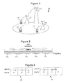
- FIG. 1 is a diagram of a communication system, according to an embodiment of the disclosure.
- FIG. 2 is a diagram illustrating aggregation of carriers, in accordance with an embodiment of the disclosure.
- FIG. 3 is a diagram illustrating alternative implementations of carrier aggregation, in accordance with an embodiment of the disclosure.
- FIG. 4 is a diagram illustrating an example of DCI (Downlink Control Information) formats used in each carrier, in accordance with an embodiment of the disclosure.
- DCI Downlink Control Information
- FIG. 5 is a diagram illustrating an example of DCI formats used in each carrier after applying padding bits, in accordance with an embodiment of the disclosure.
- FIG. 6 is a diagram illustrating an example of DCI formats used in each carrier after applying padding bits, in accordance with an embodiment of the disclosure.
- FIG. 7 is a diagram illustrating an example of DCI formats used in each carrier after applying padding bits, in accordance with an embodiment of the disclosure.
- FIG. 8 is a diagram illustrating an example of DCI formats used in each carrier after applying padding bits, in accordance with an embodiment of the disclosure.
- FIG. 9 is a diagram showing control channel elements and defining UE specific search spaces therein, in accordance with an embodiment of the disclosure.
- FIG. 10 is a diagram showing control channel elements and defining UE specific search spaces therein, in accordance with an embodiment of the disclosure.
- FIG. 11 is a diagram showing control channel elements and defining UE specific search spaces therein, in accordance with an embodiment of the disclosure.
- FIG. 12 is a flowchart illustrating a method for reducing a number of blind decodings when carrier aggregation is used, in accordance with an embodiment of the disclosure.
- FIG. 13 illustrates a processor and related components suitable for implementing the several embodiments of the present disclosure.
- CA Carrier Aggregation
- CCE Control Channel Element
- CI is defined as “Carrier Indicator.”
- CIF Carrier Indicator Field
- DCI Downlink Control Information
- eNB is defined as “E-UTRAN Node B.”
- EUTRA is defined as “Evolved Universal Terrestrial Radio Access.”
- EUTRAN is defined as “E-UTRA Network.”
- FDD Frequency Division Duplexing
- LTE Long Term Evolution
- LTE-A is defined as “LTE-Advanced.”
- RAN Radio Access Network
- RB Resource Block
- RRC Radio Resource Control
- PDCCH Physical Downlink Control Channel
- PDSCH Physical Downlink Shared Channel
- PUSCH Physical Uplink Shared Channel
- PCFICH Physical Control Format Indicator Channel
- TDD Time Division Duplexing
- Tx is defined as “Transmission.”
- UMTS Universal Mobile Telecommunications System
- the embodiments described herein relate to reducing the number of blind decodings used or required when the carrier aggregation technique described herein is in use. As described below, the number of blind decodings may become very large, resulting in an undesirable amount of resources being used and waste of the UE's battery power.
- a UE may search for two DCI formats in each of 16 possible PDCCH candidates in the UE-specific search space and 6 PDCCH candidates in the common search space. This normal search results in a maximum of 44 blind decodes per carrier.
- each downlink carrier may contain its own PDCCH.
- the UE may be required to perform a maximum of 44N blind decodes, where N is the number of currently active carriers.
- At least four different techniques are provided for reducing the number of blind decodings when carrier aggregation is used.
- the number of blind decodings may be reduced relative to the value of 44N.
- this padding method might only be applied to certain types of DCI formats.
- One possible method is that padding is applied in DCI formats which use the compact resource allocation method. By padding the DCI formats, the maximum number of blind decodings that is necessary is reduced by reducing the number of different DCI format sizes. This embodiment is described further below.
- the eNB may signal one or more reference sizes to be used to determine the number of padding bits for particular DCI formats.
- the UE receives the reference size(s)
- the UE includes padding for DCI formats having a smaller bit length such that each DCI format will have the same size as one of the reference sizes.
- an implicit method may be used to reduce the number of blind decodings when carrier aggregation is used.
- the UE determines the reference size of each DCI format based on an implicit rule.
- the reference size is the largest DCI format size among the DCI formats for which the padding bit difference is smaller than a threshold.
- the eNB may establish separate search spaces for each set of DCI format sizes which correspond to one or more carriers. This technique avoids padding between different DCI format sizes. This fourth technique also reduces the probability of blocking on the PDCCH by increasing the UE specific search space. Even though the UE search space is increased, the maximum number of blind decodings does not increase because the number of PDCCH candidates for each DCI format size remains the same. This embodiment is described further below.
- FIG. 1 illustrates an embodiment of a RAN 100 , which may be a LTE or LTE-A network as described in the 3GPP specifications.
- FIG. 1 is exemplary and may have other components or arrangements in other embodiments.
- RAN 100 may be an LTE-A network and may include one or more access nodes 110 and 140 , one or more relay nodes (RNs) 120 , and one or more UEs 130 .
- FIG. 1 shows a second access node 140 being present.
- Either access node 110 or 140 may be an eNB, a base station, or other component that promote network access for the UEs 130 .
- UEs 130 may communicate with each other via RAN 100 , may communicate with the various components of the RAN 100 shown, and may also communicate with other components not shown.
- RAN 100 may enable a wireless telecommunications system.
- FIG. 2 is a diagram illustrating aggregation of carriers, in accordance with an embodiment of the disclosure.
- carrier aggregation might be used in order to support wider transmission bandwidths and hence increase the potential peak data rate, for example, to meet LTE-A requirements.
- carrier aggregation multiple component carriers are aggregated and can be allocated in a subframe to a UA, as shown in FIG. 2 .
- each component carrier 210 a , 210 b , 210 c , 210 d , and 210 e has a width of about 20 MHz.
- the total system bandwidth is about 100 MHz. It is noted that other bandwidths such as 10 MHz can also be used by a component carrier.
- the UE may receive or transmit on a multiple, such as up to five, of component carriers, depending on the UE's capabilities.
- carrier aggregation may occur with carriers located in the same frequency band and/or carriers located in different bands. For example, one carrier may be located at 2 GHz and a second aggregated carrier may be located at 800 MHz.
- Option 1 is that the PDCCH is transmitted on the same carrier as the carrier on which the corresponding PDSCH is transmitted
- option 2 shows that the PDCCH can be transmitted on a carrier different from the carrier on which at least one of the corresponding PDSCHs is transmitted.
- the PDCCH on a component carrier assigns PDSCH resources on the same component carrier and PUSCH resources on a single linked uplink component carrier. In this case, no carrier indicator field is present. That is, the Release-8 PDCCH structure may continue to be used with the same coding, same CCE-based resource mapping, and DCI formats.
- the PDCCH on a component carrier can assign PDSCH or PUSCH resources in one of multiple component carriers using the carrier indicator field.
- Release-8 DCI formats are extended with a 1-3 bit explicit carrier indicator field.
- the length of the carrier indicator field could be semi-statically signaled by the RRC signaling.
- the remaining Release-8 PDCCH structure is reused with the same coding and same CCE-based resource mapping.
- FIG. 3 is a diagram illustrating alternative implementations of carrier aggregation, in accordance with an embodiment of the disclosure.
- FIG. 3 shows the above two alternatives.
- the first alternative shown at arrow 300 , shows the PDCCH is transmitted on the same carrier as the carrier on which the corresponding PDSCH is transmitted.
- the second alternative shown at arrow 302 , shows that the PDCCH can be transmitted on a carrier different from the carrier on which at least one of the corresponding PDSCHs is transmitted.
- a CIF may be used to indicate the carrier on which the appropriate PDSCH or PUSCH is allocated.
- the CIF requires additional signaling bits that are added to a DCI, for either a downlink resource allocation or uplink resource grant, to allow PDCCH signaling on a PDCCH monitoring carrier to refer to resources on a different carrier.
- the embodiments described herein relate, among other things, to reducing the number of blind decodings used or required when the carrier aggregation technique described above is in use.
- a feature of using an explicit CIF is that the CIF allows an eNB to indicate the carrier on which the corresponding PDSCH is transmitted.
- the CIF does not provide a reduction of the number in blind decodings when different DCI format sizes are used for each carrier.
- the number of blind decodings may be an issue in the case where two carriers are aggregated, wherein one carrier is configured in transmission mode 1 and the other carrier is configured in transmission mode 3 of LTE Rel-8 system.
- This issue might also include the UE monitoring a single PDCCH, denoted the PDCCH monitoring carrier, for resource allocations corresponding to both carriers.
- the UE should monitor DCI format 1A and 1 for the first carrier and DCI format 1A and 2A for the second carrier, respectively.
- one approach would be to not apply any additional padding bits to the DCIs. Instead, separate blind decoding is performed for different DCI format sizes. In this case, the CIF may not be required because the UE may be able to implicitly determine the carrier information via the successful decoding of a given DCI format size.
- the baseline for comparison in the embodiments is the case where each downlink carrier contains its own PDCCH. That is, the PDCCH on each downlink carrier only contains PDSCH assignments for the same downlink carrier and no CIF is used.
- a UE may search for two DCI formats in each of sixteen possible PDCCH candidates in the UE-specific search space and six PDCCH candidates in the common search space (for each subframe that the UE is monitoring). These facts results in a maximum of 44 blind decodes per carrier. For the multi-carrier situation where each downlink carrier contains its own PDCCH, the UE would perform a maximum of 44N blind decodes, where N is the number of currently active carriers. Performing this many blind decodes may be undesirable.
- Table 1 through Table 4, below, contain the bit lengths of all of the DCIs for different bandwidths, and also for the cases of FDD versus TDD, and two transmission antennas at the eNB versus 4 transmission antennas.
- DCIs 0, 1A, and 3/3A may always have the same length for a given carrier configuration.
- the lengths of DCIs 1B, 1D, 2, and 2A vary, in part, based on the number of transmission antennas in use at the eNB.
- DCI Format 1.4 MHz 3 MHz 5 MHz 10 MHz 15 MHz 20 MHz 0/1A/3/3A 21 22 25 27 27 28 1 19 23 27 31 33 39 1B 22 25 27 28 29 30 1C 8 10 12 13 14 15 1D 22 25 27 28 29 30 2 31 34 39 43 45 51 2A 28 31 36 41 42 48
- DCI Format 1.4 MHz 3 MHz 5 MHz 10 MHz 15 MHz 20 MHz 0/1A/3/3A 21 22 25 27 27 28 1 19 23 27 31 33 39 1B 25 27 28 30 31 33 1C 8 10 12 13 14 15 1D 25 27 28 30 31 33 2 34 37 42 46 48 54 2A 30 33 38 42 45 50
- DCI Format 1.4 MHz 3 MHz 5 MHz 10 MHz 15 MHz 20 MHz 0/1A/3/3A 23 25 27 29 30 31 1 22 26 30 34 36 42 1B 25 27 29 31 33 33 1C 8 10 12 13 14 15 1D 25 27 29 31 33 33 2 34 37 42 46 48 54 2A 31 34 39 43 45 51
- DCI Format 1.4 MHz 3 MHz 5 MHz 10 MHz 15 MHz 20 MHz 0/1A/3/3A 23 25 27 29 30 31 1 22 26 30 34 36 42 1B 27 29 31 33 34 35 1C 8 10 12 13 14 15 1D 27 29 31 33 34 35 2 37 41 45 49 51 57 2A 33 36 41 45 47 53
- Blocking may occur if the eNB is unable to transmit a control message to the UE in one of several designated CCEs. Blocking may arise, for example, due to other UEs being allocated those CCEs in the same subframe.
- the UE does not need to monitor the PDCCH from all carriers which may allocate PDSCH or PUSCH. So, it is likely that the eNB configures a set of PDCCH monitoring carriers and this set may be a subset of the downlink or uplink component carriers. In this case, a larger number of PDCCHs, relative to Release-8, may be transmitted on one carrier to a given UE. This fact results in an increased blocking probability, if the PDCCH search space is not also increased.
- this particular padding method reduces the required amount of blind decoding
- this particular padding method requires additional resources in terms of transmission power or time-frequency resources to transmit the redundant padding bits. That is, in order to obtain the same transmission error rate when comparing an unpadded DCI against a padded DCI (with a larger number of information bits, of which some will be redundant padding bits), greater transmission power or more time-frequency resources must be used for the latter case.
- Tables 1 to 4, above, show the DCI format size with respect to the system bandwidth and transmission mode.
- a 1.4 MHz carrier and a 20 MHz carrier may be aggregated, and a DCI format 1 is transmitted for the 1.4 MHz carrier and a DCI format 2A is transmitted for the 20 MHz carrier.
- the padding bits to make the 1.4 MHz DCI 1 equal in length to the 20 MHz DCI 2A equals 29 bits.
- this padding is larger than the actual Release-8 DCI format 1 that would be transmitted for a non-aggregated 1.4 MHz carrier.
- the embodiments described herein provide solutions whereby, for example, the padding method is applied only when the padding bit size is reasonably acceptable.
- the embodiments described herein are in addition to and different than the use of padding described above.
- the embodiments provide for various solutions for reducing blind decodings when the explicit CI bits are included in the DCI format to indicate the carrier where the PDSCH/PUSCH is transmitted.
- the size of DCI formats presented as examples herein does not include a size of CIF, so the size of DCI formats is the same as the size of DCI formats in LTE Release-8.
- the reason is because the length of CIF has not been decided from 1 to 3 bits and there is also a possibility of semi-statically configuring different CIF lengths.
- an equal-length CIF may be added to each DCI transmitted.
- adding the equal-length CIF does not necessarily mean that all DCIs increase by the length of CIF.
- the actual increase in some DCI format sizes for carrier aggregation can be less than the length of CIF. Even in this case, all of the same-sized DCI formats will increase by the same amount, which might be the length of the CIF field.
- FIG. 4 is a diagram illustrating an example of DCI formats used in each carrier, in accordance with an embodiment of the disclosure.
- FIG. 5 is a diagram illustrating an example of DCI formats used in each carrier after applying padding bits, in accordance with an embodiment of the disclosure.
- FIGS. 4 and 5 refer to the same set of four carriers, carrier set 400 and carrier set 500 . With respect to FIGS. 4 and 5 , some methods are provided to create a reasonable padding bit size while minimizing the amount of blind decoding when the carriers are aggregated with the different DCI format size.
- the padding method might be applied only to a certain type of DCI format to avoid an excessively large number of padding bits.
- One possible way of selecting these types of DCI formats is whether compact resource allocation is used in a particular DCI format. In other words, padding might only be applied in DCI formats using compact resource allocation.
- DCI format size does not significantly increase as a function of system bandwidth.
- DCI formats such as DCI format 1 require a significantly larger size as the system bandwidth is increased. The main difference is the resource allocation method.
- One kind of resource allocation uses a bitmap based resource allocation, in which each bit is used to indicate whether the corresponding resource block group is allocated or not. This technique means the required bits for the resource allocation increase linearly with the number of resource block groups. Note that the size of a resource block group also increases with the system bandwidth. Hence, the number of required bits for indicating the resource allocation may not increase completely linearly as a function of the number of resource blocks (i.e. the system bandwidth).
- the other resource allocation method is compact resource allocation, in which the starting point and the number of resource blocks are indicated.
- the resource allocation bit size increases in a log scale of the number of resource block, which is less sensitive to the number of resource blocks for the corresponding system bandwidth.
- the bitmap based resource allocation has more flexibility to allocate the RBs than the compact resource allocation.
- the resource type allocation type 0 and the resource allocation type 1 apply the BITMAP based resource allocation
- the resource type 2 applies the compact resource allocation method.
- padding may be applied if the DCI format uses compact resource allocation (DCI formats 0, 1A, 1B, 1C, 1D, 3 and 3A). It is noted that DCIs 3 and 3A may not use the compact resource allocation, but may be padded to the same length as DCIs that do use the compact resource allocation (i.e. DCIs 0 and 1A).
- the DCI format is transmitted without modification. Transmission without modification results in the UE performing blind decoding for each DCI format size.
- DCI format 1C might not be used to schedule PDSCH in the multiple carriers, because this format might only be used to schedule the PDSCH for the broadcast information (e.g. system information, paging). Hence, even if carrier aggregation has been enabled, one embodiment would be for DCI format 1C to continue to be used without a CIF field necessarily being included.
- the number of blind decodings would be 6M, where there are six unique DCI format sizes contained in Table 5 and M is the number of PDCCH candidates in which a DCI format can be transmitted within the PDCCH search space.
- M is 16 in the UE-specific search space for LTE Release-8 systems because there are 16 PDCCH candidates in this search space.
- the padding is applied to all DCI formats, such that each of the two DCIs for each carrier is padded to one of two possible total lengths with the same two total lengths being used across all carriers, then the total maximum number of blind decodings can be reduced to 2M.
- This number is the same as LTE Release-8 system where 2 different DCI format sizes are used for each transmission mode. Note that two different DCI lengths might be required in order to allow the UE to differentiate between two different DCIs.
- the maximum number of padding bits is 27 bits, which might be considered excessive and a waste of system resources.
- FIG. 5 shows the DCI formats when the method described above is applied. Because DCI format 1A uses the compact resource allocation method, padding is applied to DCI format 1A, as shown at blocks 502 and 504 .
- the maximum size of DCI format 1A is 28 bits, which is used in carrier 3 and carrier 4. So, padding bits are included in DCI format 1A of the remaining carriers (i.e. carrier 1 and carrier 2) to bring the total number of bits to 28.
- the maximum number of blind decodings in this case is 5M because there are 5 unique DCI format sizes to be searched for, which is smaller than the originally expected value of 6M.
- padding is applied to particular DCI formats corresponding to each carrier so that all of the DCIs of a particular format (or with a particular format size) have the same size as the largest DCI with the same DCI format (e.g. DCI format 1A) across all of the carriers.
- padding is applied to all DCI formats using the compact resource allocation (across all carriers referenced by the same PDCCH) so that these DCI formats have the same size as the largest DCI among the DCIs in that group of DCIs (i.e. DCIs which use the compact resource allocation).
- DCI format 1A when the UE receives DCI format 1A and DCI format 1B and the size of DCI format 1A is smaller than DCI format 1B, padding is applied to the DCI format 1A so that it has the same length as the DCI format 1B.
- a new type indicator field for example 1 bit to indicate among the two original unpadded DCI format sizes corresponding to a transmission mode
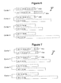
- FIG. 6 is a diagram illustrating an example of DCI formats used in each carrier, in accordance with an embodiment of the disclosure.
- FIG. 7 is a diagram illustrating an example of DCI formats used in each carrier, in accordance with an embodiment of the disclosure.
- FIGS. 6 and 7 refer to the same set of four carriers, carrier set 600 and carrier set 700 .
- the eNB may signal one or more reference sizes, which are used to determine the number of padding bits, following a pre-defined or semi-statically configured padding rules, for example, minimizing the padding bits.
- the UE receives the reference sizes, the UE applies the padding for the DCI format having a smaller bit size to increase it so that it has the same size as one of the reference sizes.
- the exact reference size can be indicated or the carrier index and the DCI format can be signaled, and the UE knows the reference size of the DCI format of the given carrier.
- FIG. 6 shows an example based on the same configuration described in Table 5, above.
- 28 bits and 39 bits are used as the reference sizes, and the padding is applied for the same type of DCI format.
- DCI formats 1A in carrier 1 and 2 have a smaller size, their size is increased as a result of padding to the reference size, as shown at blocks 602 and 606 .
- the reference size is selected as 39 bits. So, DCI format 1 in carrier 1 is increased to 39 bits in which case 12 bits are inserted as padding bits (block 604 ). Note that DCI 2, carriers 2 and 4, is not padded in this example, because the reference size for the DCI 2 is not configured.
- a CIF may not be required because the UE may be able to implicitly detect the carrier information via the successful decoding of a given DCI format size.
- the overall maximum number of blind decodings is 4M, as opposed to 6M, because there are 4 unique DCI format sizes.
- signaling a reference size can be applied among the different DCI formats, as shown in FIG. 7 at blocks 702 , 704 , and 706 .
- DCI format 1 in carrier 1 can also include 1 bit as a padding bit (block 704 ), unlike the previous example, because the reference size 28 bits is also applied to DCI format 1 in addition to DCI format 1A.
- the number of blind decodings in this case is also 4M but the maximum number of padding bits is 3 bits.
- This example is more efficient than when the padding is applied between the same DCI formats resulting in 12 padding bits (block 604 in FIG. 6 ).
- the different DCI formats of same carrier can have a same DCI format size.
- the padded sizes of DCI format 1A and DCI format 1 in carrier 1 are the same.
- a new type indicator field (for example 1 bit to indicate among the two DCI format sizes corresponding to a transmission mode) might be required to let the UE know which DCI format is transmitted with the same carrier indicator.
- both of these DCIs contain at least one padding bit, so a padding bit could be reserved in this instance to act as a type indicator. This technique would mean that the DCI lengths might not need to be further increased.
- the eNB may signal one or more reference sizes. These reference sizes may or may not be linked to a specific DCI format. Note that multiple reference sizes could be signaled for a particular DCI format.
- the eNB may pad to the next higher reference size in order to reduce the padding bits. If no next higher reference size exists, that is if the length of the DCI is higher than the highest reference length that has been signaled to the UE, then no padding occurs.
- a similar padding procedure as at the eNB may be applied to remove or ignore the padding bits.
- the UE and the eNB may have a common understanding on the padding.
- This padding rule could be pre-configured or semi-statically signaled from the eNB to the UE.
- This approach can be used for all DCIs with different resource block allocation approaches. This approach may be especially useful for padding signaling DCIs that do not use the compact resource block allocation approach (especially DCIs 1, 2, 2A) in order to potentially reduce the total number of different DCI format sizes that the UE must search for while still avoiding padding a particular DCI with an excessive number of padding bits.
- FIG. 8 is a diagram illustrating an example of DCI formats used in each carrier. A set 800 of four carriers is shown.
- the UE may determine the reference size of each DCI format based on an implicit rule.
- the reference size is the largest DCI format size among the DCI formats of which the padding bit difference is smaller than a threshold.
- This threshold may be specified as either an absolute value (for example 10 bits) or a relative percentage (for example 20%). For the latter case, if a 20% percentage threshold is used and the DCI in question normally has a length of 25 bits (for example DCI 1A for 5 MHz FDD), then it is allowable for up to five padding bits (20% of 25) to be added to that DCI.
- an implicit rule may be specified by the standards or may be signaled to the UE initially.
- the UE may check DCI format 1A in carriers 1, 2, 3 and 4.
- the UE checks the difference between DCI format 1A sizes starting from the smallest size. Because the difference between the DCI format 1A size of carrier 1 and the remaining carriers is smaller than a threshold, all carriers may be included in the same group. In the group, the largest one may be the reference one.
- the UE may check the difference between DCI format size of the DCI format 1As not included in the previous group. In this example, there are no remaining carriers, so the UE may stop checking.
- the UE may check DCI format 1 in carrier 1 and carrier 3.
- the difference is larger than 10 bits. Therefore, padding is not applied. Consequently, separate blind decoding for each DCI format size may be used.
- a CIF may not be required because the UE may be able to implicitly detect the carrier information via the successful decoding of a given DCI format size.
- the UE may check DCI format 2 in carriers 2 and 4.
- the difference is 8 bits, which is smaller than 10 bits. Therefore, the DCI formats are included in the same group, and the reference size is 54 bits.
- FIG. 8 shows the DCI format sizes for each carrier after the padding bits are included, in accordance with an embodiment of the disclosure.
- DCI formats 1A in carrier 1, 2, 3, and 4 each have a length of 27 bits
- DCI formats 2 in carriers 2 and 3 have a length of 54 bits.
- the DCI format 1A is padded to be set at 28 bits (blocks 802 and 804 ), which is equal to the DCI format 1A length in carriers 3 and 4.
- the DCI format 2 in carrier 2 is set to 54 bits (block 806 ), which is the same as the DCI format 2 in carrier 4.
- the overall maximum number of blind decodings is 4M, as opposed to 6M.
- this implicit method can also be applied for the different DCI formats.
- the different DCI formats of the same carrier can have the same DCI format size.
- the type indicator might be required to let the UE know which DCI format is transmitted with the same carrier indicator.
- a hybrid technique may be used wherein signaling the reference size and an implicit rule are used.
- the signaling of the reference size method is applied; otherwise, the implicit rule method described above is applied.
- the parameters used by implicit rule may be signaled to the UE initially.
- FIG. 9 is a diagram showing control channel elements (CCE) and defining UE specific search spaces therein, in accordance with an embodiment of the disclosure.
- CCE blocks align with each other, as shown.
- Decoding using different DCI format sizes (number of bits) is shown as either “X” or double-lined “X”, depending on which scheme is to be used.
- the symbol “Ag” in FIG. 9 always refers to the term “Aggregation Level”; thus, “Ag.1” refers to “Aggregation Level 1.”
- FIG. 9 represents one embodiment for reducing the blocking probability without increasing the maximum number of blind decodings.
- the technique shown in FIG. 9 may also be used to avoid padding between different DCI format sizes.
- the eNB may establish separate search spaces for each set of DCI format sizes which correspond to one or more carriers. This embodiment reduces the blocking probability by increasing the UE specific search space in an UE. Multiple search spaces may be defined for the UE to receive the PDCCH. However, it does not increase the number of blind decodings because separate UE specific search spaces are assigned for the different DCI format sizes which already require separate blind decoding. Effectively, it has a smaller number of blind decodings than the case when the PDCCHs are transmitted in the same carrier in which PDSCH/PUSCH is transmitted.
- carrier f1 is a 10 MHz carrier using transmission mode 1
- carrier f2 is a 20 MHz carrier using transmission mode 4.
- the UE would need to decode DCI formats of size 34 and 29 bits for carrier f1 and 54 and 31 bits for carrier f2. This result essentially increases the blind decoding by a factor of 2, from 2M to 4M.
- the size of the search space (M) will likely have to be extended to accommodate carrier aggregation to maintain the same blocking probability as Release-8, so the actual increase in blind decoding will be from 2M to 4M′, where M′ is likely on the order of 2M, which is twice as large.
- each PDCCH candidate may only be blind decoded using two DCI format sizes, as illustrated in FIG. 9 , which shows an example of a UE specific search space.
- the PDCCH candidates may be divided among the potential DCI format sizes in alternating fashion. Because each candidate is associated with a particular set of DCI formats, the only increase in blind decoding, relative to Release-8, is due to the increased search space. Blind decoding might be increased from 2M in Release-8 to 2M′ relative to Release-10, where M is the size of the search space in Release-8 and M′ is the size of the search space for carrier aggregation in Release-10.
- FIG. 10 is a diagram showing control channel elements and defining UE specific search spaces therein, in accordance with an embodiment of the disclosure.
- CCE blocks align with each other, as shown.
- Decoding using different DCI formats (number of bits) is shown as either “X” or double-lined “X”, depending on which scheme is to be used.
- the symbol “Ag” in FIG. 9 always refers to the term “Aggregation Level;” thus, “Ag.1” refers to “Aggregation Level 1.”
- the embodiment described with respect to FIG. 9 may be extended to more than two carriers. For example, if there is a third carrier, f3, which is 20 MHz using transmission mode 4, then the above decoding scheme could be used or more candidates could be dedicated to decoding 54 and 31 . This implementation is shown in FIG. 10 .
- FIG. 11 is a diagram showing control channel elements and defining UE specific search spaces therein, in accordance with an embodiment of the disclosure.
- CCE blocks align with each other, as shown.
- Decoding using different DCI formats is shown as either “X” or double-lined “X”, depending on which scheme is to be used.
- the embodiment described with respect to FIG. 11 may be combined with one of the padding solutions described above.
- the smaller DCI format may be padded so that its size equals the larger DCI format.
- the term “not sufficiently hinder” may be quantified by the use of a predetermined or otherwise configured threshold that measures system performance.
- the DCI formats for the 29 bits case are padded to 31 bits.
- any PDCCH candidate may be used to allocate resources for any carrier using a DCI format size of 31 bits.
- particular PDCCH candidates may also be associated with particular reference sizes, which may be explicitly or implicitly signaled.
- FIG. 12 is a flowchart illustrating a method for reducing a number of blind decodings when carrier aggregation is used, in accordance with an embodiment of the disclosure.
- the method shown in FIG. 12 may be implemented in a UE (or a network access device) or an eNB, such as those shown in FIG. 1 .
- the method shown in FIG. 12 may be implemented using a processor and/or other components, such as those shown in FIG. 13 .
- the method shown in FIG. 12 reflects one or more embodiments as described with respect to FIGS. 2 through 11 , and the method shown in FIG. 12 may be expanded and/or modified according to the embodiments described elsewhere herein.
- the method begins as the device includes additional padding in less than all downlink control information (DCI) formats (block 1200 ). The process terminates thereafter.
- DCI downlink control information
- the device includes padding in less than all DCI formats when the UE is configured for carrier aggregation with at least two of the carriers having different system bandwidths. In some embodiments, the device includes padding in less than all DCI formats when the UE is configured for carrier aggregation with at least two of the carriers corresponding to different transmission modes and the different bandwidths.
- FIG. 13 illustrates an example of a system 1300 that includes a processing component, such as processor 1310 , suitable for implementing one or more embodiments disclosed herein.
- the system 1300 might include network connectivity devices 1320 , random access memory (RAM) 1330 , read only memory (ROM) 1340 , secondary storage 1350 , and input/output (I/O) devices 1360 . These components might communicate with one another via a bus 1370 .
- DSP digital signal processor
- the processor 1310 executes instructions, codes, computer programs, or scripts that it might access from the network connectivity devices 1320 , RAM 1330 , ROM 1340 , or secondary storage 1350 (which might include various disk-based systems such as hard disk, floppy disk, or optical disk). While only one CPU 1310 is shown, multiple processors may be present. Thus, while instructions may be discussed as being executed by a processor, the instructions may be executed simultaneously, serially, or otherwise by one or multiple processors.
- the processor 1310 may be implemented as one or more CPU chips.
- the network connectivity devices 1320 may take the form of modems, modem banks, Ethernet devices, universal serial bus (USB) interface devices, serial interfaces, token ring devices, fiber distributed data interface (FDDI) devices, wireless local area network (WLAN) devices, radio transceiver devices such as code division multiple access (CDMA) devices, global system for mobile communications (GSM) radio transceiver devices, worldwide interoperability for microwave access (WiMAX) devices, and/or other well-known devices for connecting to networks.
- These network connectivity devices 1320 may enable the processor 1310 to communicate with the Internet or one or more telecommunications networks or other networks from which the processor 1310 might receive information or to which the processor 1310 might output information.
- the network connectivity devices 1320 might also include one or more transceiver components 1325 capable of transmitting and/or receiving data wirelessly.
- the RAM 1330 might be used to store volatile data and perhaps to store instructions that are executed by the processor 1310 .
- the ROM 1340 is a non-volatile memory device that typically has a smaller memory capacity than the memory capacity of the secondary storage 1350 .
- ROM 1340 might be used to store instructions and perhaps data that are read during execution of the instructions. Access to both RAM 1330 and ROM 1340 is typically faster than to secondary storage 1350 .
- the secondary storage 1350 is typically comprised of one or more disk drives or tape drives and might be used for non-volatile storage of data or as an over-flow data storage device if RAM 1330 is not large enough to hold all working data. Secondary storage 1350 may be used to store programs that are loaded into RAM 1330 when such programs are selected for execution.
- the I/O devices 1360 may include liquid crystal displays (LCDs), touch screen displays, keyboards, keypads, switches, dials, mice, track balls, voice recognizers, card readers, paper tape readers, printers, video monitors, or other well-known input/output devices.
- the transceiver 1325 might be considered to be a component of the I/O devices 1360 instead of or in addition to being a component of the network connectivity devices 1320 .
- the embodiments provide for a method for reducing a number of blind decodings to be performed when carrier aggregation is being used. Padding is included in less than all downlink control information (DCI) formats.
- DCI downlink control information
- the embodiments may be implemented in a UE, an access node, or possibly both together as a system. Either a UE or an access node may be embodied as a processor configured to perform the embodiments described herein.
Landscapes
- Engineering & Computer Science (AREA)
- Signal Processing (AREA)
- Computer Networks & Wireless Communication (AREA)
- Mobile Radio Communication Systems (AREA)
- Communication Control (AREA)
Priority Applications (1)
| Application Number | Priority Date | Filing Date | Title |
|---|---|---|---|
| US13/457,294 US8958366B2 (en) | 2009-10-30 | 2012-04-26 | Reducing blind decodings for communications using carrier aggregation |
Applications Claiming Priority (3)
| Application Number | Priority Date | Filing Date | Title |
|---|---|---|---|
| US25683909P | 2009-10-30 | 2009-10-30 | |
| PCT/US2010/054842 WO2011053851A2 (fr) | 2009-10-30 | 2010-10-29 | Réduction des décodages aveugles pour des communications utilisant une agrégation de porteuses |
| US13/457,294 US8958366B2 (en) | 2009-10-30 | 2012-04-26 | Reducing blind decodings for communications using carrier aggregation |
Related Parent Applications (1)
| Application Number | Title | Priority Date | Filing Date |
|---|---|---|---|
| PCT/US2010/054842 Continuation WO2011053851A2 (fr) | 2009-10-30 | 2010-10-29 | Réduction des décodages aveugles pour des communications utilisant une agrégation de porteuses |
Publications (2)
| Publication Number | Publication Date |
|---|---|
| US20130016655A1 US20130016655A1 (en) | 2013-01-17 |
| US8958366B2 true US8958366B2 (en) | 2015-02-17 |
Family
ID=43827337
Family Applications (1)
| Application Number | Title | Priority Date | Filing Date |
|---|---|---|---|
| US13/457,294 Active 2031-05-24 US8958366B2 (en) | 2009-10-30 | 2012-04-26 | Reducing blind decodings for communications using carrier aggregation |
Country Status (7)
| Country | Link |
|---|---|
| US (1) | US8958366B2 (fr) |
| EP (1) | EP2494755B1 (fr) |
| JP (1) | JP2013509832A (fr) |
| KR (1) | KR101697807B1 (fr) |
| CN (1) | CN102859956B (fr) |
| CA (1) | CA2779297C (fr) |
| WO (2) | WO2011053856A2 (fr) |
Cited By (7)
| Publication number | Priority date | Publication date | Assignee | Title |
|---|---|---|---|---|
| US9345018B2 (en) | 2009-10-30 | 2016-05-17 | Blackberry Limited | Downlink control information set switching when using carrier aggregation |
| US9686798B1 (en) * | 2015-01-14 | 2017-06-20 | Cisco Technology, Inc. | System and method for providing collision-avoided physical downlink control channel resource allocation in a network environment |
| US10225698B2 (en) | 2014-07-03 | 2019-03-05 | Cisco Technology, Inc. | System and method for providing message delivery and paging to a group of users in a network environment |
| US10326578B2 (en) | 2017-02-13 | 2019-06-18 | At&T Intellectual Property I, L.P. | Early termination scheme for blind decoding of a downlink control channel |
| US20220166559A1 (en) * | 2018-08-23 | 2022-05-26 | Guangdong Oppo Mobile Telecommunications Corp., Ltd. | Feedback information transmission method and apparatus and communications device |
| US20230283401A1 (en) * | 2019-03-22 | 2023-09-07 | Samsung Electronics Co., Ltd. | Scheduling in communication systems with multiple service types |
| US11997041B2 (en) | 2020-06-17 | 2024-05-28 | At&T Intellectual Property I, L.P. | Early termination scheme for blind decoding of a downlink control channel |
Families Citing this family (35)
| Publication number | Priority date | Publication date | Assignee | Title |
|---|---|---|---|---|
| US8824405B2 (en) * | 2010-01-08 | 2014-09-02 | Lg Electronics Inc. | Method and apparatus for receiving a downlink signal in a wireless communication system supporting carrier aggregation |
| EP2672651B1 (fr) * | 2010-02-11 | 2018-03-28 | Huawei Technologies Co., Ltd. | Méthode, station de base, équipement d'utilisateur, et système pour envoyer et recevoir des signaux PDCCH |
| PL3432501T3 (pl) | 2010-04-30 | 2021-03-08 | Guangdong Oppo Mobile Telecommunications Corp., Ltd. | System i sposób współdzielenia kanału kontrolnego dla agregacji nośnych |
| US20110267948A1 (en) * | 2010-05-03 | 2011-11-03 | Koc Ali T | Techniques for communicating and managing congestion in a wireless network |
| EP2673911B1 (fr) * | 2011-02-10 | 2017-01-25 | Telefonaktiebolaget LM Ericsson (publ) | Allocation de ressource pour signaux de référence dans un système multi-porteuse |
| PL2919545T3 (pl) * | 2011-02-11 | 2017-12-29 | Interdigital Patent Holdings, Inc. | Urządzenie oraz sposób dla rozszerzonego kanału sterowania (e-pdcch) |
| CN103430469B (zh) * | 2011-03-14 | 2016-08-17 | Lg电子株式会社 | 用于在无线通信系统中发送控制信息的方法和设备 |
| US9042277B2 (en) * | 2011-04-11 | 2015-05-26 | Qualcomm Incorporated | Transmission of control information for FDD-TDD carrier aggregation |
| CN102811495A (zh) * | 2011-06-02 | 2012-12-05 | 华为技术有限公司 | 接收、发送调度信息的方法、装置及系统 |
| EP2742720B1 (fr) * | 2011-08-12 | 2019-03-27 | Telefonaktiebolaget LM Ericsson (publ) | Noeud de réseau radio, équipement utilisateur et leurs procédés |
| US8989121B2 (en) * | 2011-11-02 | 2015-03-24 | Qualcomm Incorporated | Blindly decoding interfering cell PDCCH to acquire interfering cell PDSCH transmission information |
| ES2627519T3 (es) * | 2011-11-04 | 2017-07-28 | Intel Corporation | Programación de recursos de enlace descendente |
| JP5995174B2 (ja) | 2012-02-16 | 2016-09-21 | サン パテント トラスト | 受信装置、送信装置、受信方法及び送信方法 |
| CN104272640B (zh) | 2012-03-16 | 2017-10-24 | 诺基亚通信公司 | 盲解码 |
| US9131498B2 (en) | 2012-09-12 | 2015-09-08 | Futurewei Technologies, Inc. | System and method for adaptive transmission time interval (TTI) structure |
| US9787458B2 (en) | 2013-09-16 | 2017-10-10 | Nec Corporation | Methods and apparatus relating to LTE FDD-TDD inter-system carrier aggregation in advanced wireless communication systems |
| EP2883404A4 (fr) * | 2013-09-16 | 2016-06-22 | Nec Corp | Procédés et appareils liés à agrégation de porteuses inter-système lte fdd-tdd, dans des systèmes de communications sans fil avancés |
| US9544892B2 (en) * | 2013-09-27 | 2017-01-10 | Apple Inc. | System and method for searching for a control channel |
| US9497008B2 (en) * | 2013-09-27 | 2016-11-15 | Apple Inc. | System and method for searching for grants and assignments in a PDCCH |
| US9674727B2 (en) * | 2014-01-17 | 2017-06-06 | Qualcomm Incorporated | Indication of cell mode and CSI feedback rules for cell on-off procedure |
| US10721720B2 (en) | 2014-01-30 | 2020-07-21 | Qualcomm Incorporated | Cell On-Off procedure for dual connectivity |
| WO2016183545A1 (fr) * | 2015-05-14 | 2016-11-17 | Walleye Software, LLC | Récupération distribuée et optimisée des éléments superflus parmi des liens de pointeur de table distante et exportée pour actualiser des noeuds de graphe de propagation |
| EP3317974A1 (fr) * | 2015-07-02 | 2018-05-09 | Nextivity, Inc. | Procédé et système de maximisation de la bande passante de canal tout en employant un codage de contrôle d'erreur |
| US10841911B2 (en) | 2015-10-02 | 2020-11-17 | Lg Electronics Inc. | Method for transmitting downlink control information in wireless communication system |
| KR102083969B1 (ko) * | 2016-01-08 | 2020-03-03 | 엘지전자 주식회사 | 무선 통신 시스템에서 무선 신호 송수신 방법 및 장치 |
| US10349440B2 (en) * | 2016-04-11 | 2019-07-09 | Qualcomm Incorporated | Feedback mechanism to activate and/or deactivate a semi-persistent scheduling grant |
| CN109565488B (zh) * | 2016-11-03 | 2022-07-29 | 松下电器(美国)知识产权公司 | 基站、用户设备和无线通信方法 |
| CN108923895B (zh) * | 2017-03-23 | 2021-08-13 | 华为技术有限公司 | 信息传输方法、装置及系统 |
| CN111818650B (zh) * | 2017-10-20 | 2022-01-11 | 华为技术有限公司 | 下行控制信息的传输、盲检测次数的获取方法和装置 |
| CN110034842A (zh) * | 2018-01-12 | 2019-07-19 | 中国移动通信有限公司研究院 | 一种传输dci的方法及装置、设备、存储介质 |
| CN111148230B (zh) * | 2018-11-02 | 2022-11-08 | 华为技术有限公司 | 传输下行控制信息的方法和装置 |
| WO2020092941A1 (fr) * | 2018-11-02 | 2020-05-07 | Intel Corporation | Indication de temps d'occupation de canal pour une opération sans licence basée sur nr |
| US11233601B2 (en) * | 2019-04-15 | 2022-01-25 | Mediatek Singapore Pte. Ltd. | Method and apparatus for downlink control information size alignment in mobile communications |
| CN113541888B (zh) * | 2020-04-13 | 2022-11-22 | 维沃移动通信有限公司 | 资源确定方法、指示方法及设备 |
| CN113543325A (zh) * | 2020-04-17 | 2021-10-22 | 维沃移动通信有限公司 | 下行控制信息dci传输方法和通信设备 |
Citations (20)
| Publication number | Priority date | Publication date | Assignee | Title |
|---|---|---|---|---|
| US7260405B2 (en) * | 2003-04-30 | 2007-08-21 | Samsung Electronics Co., Ltd. | Method for measuring and reporting channel quality in a broadband wireless access communication system |
| US20090088148A1 (en) | 2007-09-28 | 2009-04-02 | Lg Electronics Inc. | Wireless communication system for monitoring physical downlink control channel |
| CN101505498A (zh) | 2009-03-17 | 2009-08-12 | 中兴通讯股份有限公司 | 下行控制信息发送方法及相关系统、装置 |
| CN101541063A (zh) | 2009-04-27 | 2009-09-23 | 中兴通讯股份有限公司 | 一种下行控制信令的传输方法和装置 |
| US20090239568A1 (en) * | 2008-03-18 | 2009-09-24 | Pierre Bertrand | Scheduling request usage in drx mode in wireless networks |
| US20090300456A1 (en) | 2008-04-25 | 2009-12-03 | Interdigital Patent Holdings, Inc. | Harq process utilization in multiple carrier wireless communications |
| US20090307554A1 (en) | 2008-04-25 | 2009-12-10 | Interdigital Patent Holdings, Inc. | Method and apparatus for performing a bundled transmission |
| US20090305698A1 (en) | 2008-06-09 | 2009-12-10 | Samsung Electronics Co., Ltd. | Downlink control information format for multiple codeword transmission |
| US20100034303A1 (en) | 2008-08-11 | 2010-02-11 | Qualcomm Incorporated | Downlink grants in a multicarrier wireless communication system |
| US20100080187A1 (en) * | 2008-09-26 | 2010-04-01 | Samsung Electronics Co., Ltd. | Apparatus and method for supporting transmission of sounding reference signals from multiple antennas |
| US20100188965A1 (en) * | 2009-01-23 | 2010-07-29 | Qualcomm Incorporated | Methods and systems for wimax broadcasting messages processing |
| US20100195614A1 (en) * | 2009-02-03 | 2010-08-05 | Motorola, Inc. | Method and Apparatus for Transport Block Signaling in a Wireless Communication System |
| US20100227569A1 (en) | 2008-10-20 | 2010-09-09 | Interdigital Patent Holdings, Inc. | Control channel signaling and acquisition for carrier aggregation |
| US20100232373A1 (en) * | 2009-03-16 | 2010-09-16 | Motorola, Inc. | Resource Allocation in Wireless Communication Systems |
| US20100238984A1 (en) * | 2009-03-19 | 2010-09-23 | Motorola, Inc. | Spatial Information Feedback in Wireless Communication Systems |
| US20100322158A1 (en) | 2009-06-22 | 2010-12-23 | Lee Jung A | Indicating dynamic allocation of component carriers in multi-component carrier systems |
| US20110044239A1 (en) | 2009-08-21 | 2011-02-24 | Zhijun Cai | System and method for carrier activation |
| US8009606B2 (en) | 2008-11-13 | 2011-08-30 | Lg Electronics Inc. | Method and apparatus for indicating deactivation of semi-persistent scheduling |
| US8379581B2 (en) | 2008-12-08 | 2013-02-19 | Sharp Kabushiki Kaisha | Systems and methods for uplink power control |
| US8537724B2 (en) | 2009-03-17 | 2013-09-17 | Motorola Mobility Llc | Relay operation in a wireless communication system |
-
2010
- 2010-10-29 KR KR1020127014057A patent/KR101697807B1/ko active IP Right Grant
- 2010-10-29 WO PCT/US2010/054848 patent/WO2011053856A2/fr active Application Filing
- 2010-10-29 CN CN201080060290.9A patent/CN102859956B/zh active Active
- 2010-10-29 WO PCT/US2010/054842 patent/WO2011053851A2/fr active Application Filing
- 2010-10-29 EP EP10779133.7A patent/EP2494755B1/fr active Active
- 2010-10-29 JP JP2012537142A patent/JP2013509832A/ja not_active Withdrawn
- 2010-10-29 CA CA2779297A patent/CA2779297C/fr active Active
-
2012
- 2012-04-26 US US13/457,294 patent/US8958366B2/en active Active
Patent Citations (22)
| Publication number | Priority date | Publication date | Assignee | Title |
|---|---|---|---|---|
| US7260405B2 (en) * | 2003-04-30 | 2007-08-21 | Samsung Electronics Co., Ltd. | Method for measuring and reporting channel quality in a broadband wireless access communication system |
| US20090088148A1 (en) | 2007-09-28 | 2009-04-02 | Lg Electronics Inc. | Wireless communication system for monitoring physical downlink control channel |
| US8401542B2 (en) * | 2007-09-28 | 2013-03-19 | Lg Electronics Inc. | Wireless communication system for monitoring physical downlink control channel |
| US20090239568A1 (en) * | 2008-03-18 | 2009-09-24 | Pierre Bertrand | Scheduling request usage in drx mode in wireless networks |
| US8239721B2 (en) | 2008-04-25 | 2012-08-07 | Interdigital Patent Holdings, Inc. | HARQ process utilization in multiple carrier wireless communications |
| US20090300456A1 (en) | 2008-04-25 | 2009-12-03 | Interdigital Patent Holdings, Inc. | Harq process utilization in multiple carrier wireless communications |
| US20090307554A1 (en) | 2008-04-25 | 2009-12-10 | Interdigital Patent Holdings, Inc. | Method and apparatus for performing a bundled transmission |
| US20090305698A1 (en) | 2008-06-09 | 2009-12-10 | Samsung Electronics Co., Ltd. | Downlink control information format for multiple codeword transmission |
| US20100034303A1 (en) | 2008-08-11 | 2010-02-11 | Qualcomm Incorporated | Downlink grants in a multicarrier wireless communication system |
| US20100080187A1 (en) * | 2008-09-26 | 2010-04-01 | Samsung Electronics Co., Ltd. | Apparatus and method for supporting transmission of sounding reference signals from multiple antennas |
| US20100227569A1 (en) | 2008-10-20 | 2010-09-09 | Interdigital Patent Holdings, Inc. | Control channel signaling and acquisition for carrier aggregation |
| US8009606B2 (en) | 2008-11-13 | 2011-08-30 | Lg Electronics Inc. | Method and apparatus for indicating deactivation of semi-persistent scheduling |
| US8379581B2 (en) | 2008-12-08 | 2013-02-19 | Sharp Kabushiki Kaisha | Systems and methods for uplink power control |
| US20100188965A1 (en) * | 2009-01-23 | 2010-07-29 | Qualcomm Incorporated | Methods and systems for wimax broadcasting messages processing |
| US20100195614A1 (en) * | 2009-02-03 | 2010-08-05 | Motorola, Inc. | Method and Apparatus for Transport Block Signaling in a Wireless Communication System |
| US20100232373A1 (en) * | 2009-03-16 | 2010-09-16 | Motorola, Inc. | Resource Allocation in Wireless Communication Systems |
| CN101505498A (zh) | 2009-03-17 | 2009-08-12 | 中兴通讯股份有限公司 | 下行控制信息发送方法及相关系统、装置 |
| US8537724B2 (en) | 2009-03-17 | 2013-09-17 | Motorola Mobility Llc | Relay operation in a wireless communication system |
| US20100238984A1 (en) * | 2009-03-19 | 2010-09-23 | Motorola, Inc. | Spatial Information Feedback in Wireless Communication Systems |
| CN101541063A (zh) | 2009-04-27 | 2009-09-23 | 中兴通讯股份有限公司 | 一种下行控制信令的传输方法和装置 |
| US20100322158A1 (en) | 2009-06-22 | 2010-12-23 | Lee Jung A | Indicating dynamic allocation of component carriers in multi-component carrier systems |
| US20110044239A1 (en) | 2009-08-21 | 2011-02-24 | Zhijun Cai | System and method for carrier activation |
Non-Patent Citations (40)
| Title |
|---|
| 3GPP TR 36.814 V9.0.0; 3rd Generation Partnership Project; Technical Specification Group Radio Access Network; Evolved Universal Terrestrial Radio Access (E-UTRA); Further Advancements for E-UTRA Physical Layer Aspects; Release 9; Mar. 2010; 104 pages. |
| 3GPP TS 36.212 V8.7.0; 3rd Generation Partnership Project; Technical Specification Group Radio Access Network; Evolved Universal Terrestrial Radio Access (E-UTRA); Multiplexing and Channel Coding; Release 8; May 2009; 60 pages. |
| 3GPP TS 36.213 V8.8.0; 3rd Generation Partnership Project; Technical Specification Group Radio Access Network; Evolved Universal Terrestrial Radio Access (E-UTRA); Physical Layer Procedures; Release 8; Sep. 2009; 77 pages. |
| 3GPP TSG RAN WG1 #58; "Considerations on Alternative Ways of Implementing DCI Formats for LTE-Advanced"; R1-093318; Shenzhen, China; Aug. 24-28, 2009; 2 pages. |
| 3GPP TSG RAN WG1 #58; "Control Signaling for LTE Rel-9 Enhanced DL Transmission"; R1-093408; Shenzhen, China; Aug. 24-28, 2009; 7 pages. |
| 3GPP TSG RAN WG1 #58bis Meeting; "Discussion of Carrier Indicator Signalling in Carrier Aggregation Scenario"; R1-09-3767; Miyazaki, Japan; Oct. 12-16, 2009; 3 pages. |
| 3GPP TSG RAN WG1 #58bis; "Carrier Indicator in LTE-A"; R1-094129; Miyazaki, Japan; Oct. 12-16, 2009; 2 pages. |
| 3GPP TSG RAN WG1 #58bis; "Configuration and Activation of Carrier Indicator in PDCCH for Multiple Carrier Aggregation"; R1-094161; Miyazaki, Japan; Oct. 12-16, 2009; 6 pages. |
| 3GPP TSG RAN WG1 #58bis; "Configuration and Activation of Carrier Indicator in PDCCH for Multiple Carrier Aggregation"; R1-094353; Miyazaki, Japan; Oct. 12-16, 2009; 6 pages. |
| 3GPP TSG RAN WG1 #58bis; "Interpreting the Carrier Indicator Field"; R1-094206; Miyazaki, Japan; Oct. 12-16, 2009; 3 pages. |
| 3GPP TSG RAN WG1 Meeting #57bis; "Benefits of Carrier Indicator on Multi-Channel ACK/NACK Transmission"; R1-092786; Los Angeles, CA, USA; Jun. 29-Jul. 3, 2009; 3 pages. |
| 3GPP TSG RAN WG1 Meeting #57bis; "Benefits of Carrier Indicator on Multi-Channel ACK/NACK Transmission"; R1-092846; Los Angeles, CA, USA; Jun. 29-Jul. 3, 2009; 3 pages. |
| 3GPP TSG RAN WG1 Meeting #58; "Carrier Indication for Carrier Aggregation"; R1-093296; Shenzhen, China; Aug. 24-28, 2009; 4 pages. |
| 3GPP TSG RAN WG1 Meeting #58; "Issues on Cross Carrier Scheduling"; R1-093531; Shenzhen, China; Aug. 24-28, 2009; 3 pages. |
| 3GPP TSG RAN WG1 Meeting #58; "Way Forward on PDCCH for Bandwidth Extension in LTE-A"; R1-093699; Shenzhen, China; Aug. 24-28, 2009; 2 pages. |
| 3GPP TSG RAN WG1 Meeting #58bis; "Blind Decoding for Carrier Aggregation"; R1-094117; Miyazaki, Japan; Oct. 12-16, 2009; 3 pages. |
| 3GPP TSG RAN WG2 #67bis; "Initial State for the Secondary Carrier"; R2-095718; Miyazaki, Japan; Oct. 12-16, 2009; 2 pages. |
| 3GPP TSG RAN WG2 Meeting #67-bis; "Introduction of UE Measurement Capability on Frequency Adjacent to Infra-Frequency"; R2-096045; Miyazaki, Japan; Oct. 12-16, 2009; 15 pages. |
| 3GPP TSG RAN1 #57bis; "PDCCH Design for Carrier Aggregation and Post Rel-8 Features"; R1-092641; Los Angeles, USA; Jun. 29-Jul. 3, 2009; 5 pages. |
| 3GPP TSG RAN2 Meeting #67bis; "Component Carrier Configuration/Activation for Carrier Aggregation"; R2-095576; Miyazaki, Japan; Oct. 12-16, 2009; 3 pages. |
| 3GPP TSG-RAN WG1 Meeting #58; "Component Carrier Indication Scheme for Carrier Aggregation"; R1-093465; Shenzhen, China; Aug. 24-28, 2009; 3 pages. |
| 3GPP TSG-RAN WG1 Meeting #58bis; "DCI Format and Blind Decoding for LTE-Advanced"; R1-093941; Miyazaki, Japan; Oct. 12-16, 2009; 5 pages. |
| 3GPP TSG-RAN WG2 Meeting #67bis; "LS on the Capability of Search on the Secondary Carrier"; R2-096295; Miyazaki, Japan; Oct. 12-16, 2009; 1 page. |
| 3GPP TSG-RAN2 #67bis Meeting; "The Need for Additional Activation Procedure in Carrier Aggregation"; R2-095874; Miyazaki, Japan; Oct. 12-16, 2009; 4 pages. |
| 3GPP TSG-WG2 Meeting #67bis; "Agreements on Carrier Aggregation"; R2-096292; Miyazaki, Japan; Oct. 12-16, 2009; 6 pages. |
| Canadian Office Action; Application No. 2,779,297; Aug. 22, 2013; 3 pages. |
| Canadian Office Action; Application No. 2,779,299; Nov. 15, 2013; 4 pages. |
| Chinese Office Action as Received in Co-pending Application No. 201080060288.1 on Jun. 4, 2014; 6 pages. (No English translation available). |
| Chinese Office Action as Received in Co-Pending Application No. 201080060290.9 on Aug. 5, 2014; 5 pages.(No English translation available). |
| Earnshaw, Andrew Mark, et al.; U.S. Appl. No. 13/457,313, filed Apr. 26, 2012; Title: Downlink Cntrol Information Set Switching when Using Carrier Aggregation. |
| Earnshaw, Andrew Mark, et al.; U.S. Appl. No. 14/292,458, filed May 30, 2014; Title: Downlink Control Information Set Switching When Using Carrier Aggregation. |
| Notice of Allowance dated May 9, 2014; U.S. Appl. No. 13/457,313, filed Apr. 26, 2012; 14 pages. |
| Office Action dated Apr. 23, 2014; U.S. Appl. No. 13/457,313, filed Apr. 26, 2012; 30 pages. |
| Office Action dated Aug. 14, 2014; U.S. Appl. No. 14/292,458, filed May 30, 2014; 28 pages. |
| PCT International Search Report; Application No. PCT/US2010/054842; Apr. 21, 2011; 3 pages. |
| PCT International Search Report; Application No. PCT/US2010/054848; Apr. 28, 2011; 5 pages. |
| PCT International Search Report; Application No. PCT/US2010/054849; Mar. 31, 2011; 3 pages. |
| PCT Written Opinion of the International Searching Authority; Application No. PCT/US2010/054842; Apr. 21, 2011; 5 pages. |
| PCT Written Opinion of the International Searching Authority; Application No. PCT/US2010/054848; Apr. 28, 2011; 4 pages. |
| PCT Written Opinion of the International Searching Authority; Application No. PCT/US2010/054849; Mar. 31, 2011; 7 pages. |
Cited By (8)
| Publication number | Priority date | Publication date | Assignee | Title |
|---|---|---|---|---|
| US9345018B2 (en) | 2009-10-30 | 2016-05-17 | Blackberry Limited | Downlink control information set switching when using carrier aggregation |
| US10225698B2 (en) | 2014-07-03 | 2019-03-05 | Cisco Technology, Inc. | System and method for providing message delivery and paging to a group of users in a network environment |
| US9686798B1 (en) * | 2015-01-14 | 2017-06-20 | Cisco Technology, Inc. | System and method for providing collision-avoided physical downlink control channel resource allocation in a network environment |
| US10326578B2 (en) | 2017-02-13 | 2019-06-18 | At&T Intellectual Property I, L.P. | Early termination scheme for blind decoding of a downlink control channel |
| US10728004B2 (en) | 2017-02-13 | 2020-07-28 | At&T Intellectual Property I, L.P. | Early termination scheme for blind decoding of a downlink control channel |
| US20220166559A1 (en) * | 2018-08-23 | 2022-05-26 | Guangdong Oppo Mobile Telecommunications Corp., Ltd. | Feedback information transmission method and apparatus and communications device |
| US20230283401A1 (en) * | 2019-03-22 | 2023-09-07 | Samsung Electronics Co., Ltd. | Scheduling in communication systems with multiple service types |
| US11997041B2 (en) | 2020-06-17 | 2024-05-28 | At&T Intellectual Property I, L.P. | Early termination scheme for blind decoding of a downlink control channel |
Also Published As
| Publication number | Publication date |
|---|---|
| CN102859956B (zh) | 2016-01-13 |
| WO2011053856A2 (fr) | 2011-05-05 |
| CA2779297A1 (fr) | 2011-05-05 |
| CN102859956A (zh) | 2013-01-02 |
| EP2494755A2 (fr) | 2012-09-05 |
| KR20120085879A (ko) | 2012-08-01 |
| WO2011053851A2 (fr) | 2011-05-05 |
| WO2011053856A3 (fr) | 2011-06-23 |
| JP2013509832A (ja) | 2013-03-14 |
| EP2494755B1 (fr) | 2016-01-06 |
| US20130016655A1 (en) | 2013-01-17 |
| WO2011053851A3 (fr) | 2011-06-23 |
| KR101697807B1 (ko) | 2017-01-18 |
| CA2779297C (fr) | 2015-04-14 |
Similar Documents
| Publication | Publication Date | Title |
|---|---|---|
| US8958366B2 (en) | Reducing blind decodings for communications using carrier aggregation | |
| US11128495B2 (en) | Systems and methods for high-reliability ultra-reliable low latency communication transmissions | |
| US11057891B2 (en) | Methods and related devices for performing cross-carrier scheduling with beam operations | |
| US10548127B2 (en) | Apparatus and method of avoiding control channel blocking | |
| US9100957B2 (en) | Downlink control information set switching when using carrier aggregation | |
| US8606286B2 (en) | E-PDCCH design for reducing blind decoding | |
| CN108134662B (zh) | 终端装置、基站装置以及通信方法 | |
| US10588127B2 (en) | Method for communicating in a mobile network | |
| EP2512051A2 (fr) | Procédé et appareil permettant de contrôler un canal de signalisation dans un système de communication sans fil | |
| US11765741B2 (en) | Radio communication method, chip, and system | |
| US9544892B2 (en) | System and method for searching for a control channel | |
| EP3496480A1 (fr) | Procédé, appareil et système pour envoyer des informations de commande |
Legal Events
| Date | Code | Title | Description |
|---|---|---|---|
| AS | Assignment |
Owner name: RESEARCH IN MOTION LIMITED, ONTARIO Free format text: ASSIGNMENT OF ASSIGNORS INTEREST;ASSIGNOR:RESEARCH IN MOTION CORPORATION;REEL/FRAME:028496/0638 Effective date: 20120704 |
|
| AS | Assignment |
Owner name: RESEARCH IN MOTION LIMITED, CANADA Free format text: ASSIGNMENT OF ASSIGNORS INTEREST;ASSIGNORS:HEO, YOUN HYOUNG;EARNSHAW, ANDREW MARK;FONG, MO-HAN;AND OTHERS;SIGNING DATES FROM 20111003 TO 20121016;REEL/FRAME:029288/0867 Owner name: RESEARCH IN MOTION CORPORATION, DELAWARE Free format text: ASSIGNMENT OF ASSIGNORS INTEREST;ASSIGNORS:MCBEATH, SEAN;CAI, ZHIJUN;REEL/FRAME:029288/0904 Effective date: 20111004 |
|
| AS | Assignment |
Owner name: BLACKBERRY LIMITED, ONTARIO Free format text: CHANGE OF NAME;ASSIGNOR:RESEARCH IN MOTION LIMITED;REEL/FRAME:034688/0899 Effective date: 20130709 |
|
| STCF | Information on status: patent grant |
Free format text: PATENTED CASE |
|
| MAFP | Maintenance fee payment |
Free format text: PAYMENT OF MAINTENANCE FEE, 4TH YEAR, LARGE ENTITY (ORIGINAL EVENT CODE: M1551); ENTITY STATUS OF PATENT OWNER: LARGE ENTITY Year of fee payment: 4 |
|
| MAFP | Maintenance fee payment |
Free format text: PAYMENT OF MAINTENANCE FEE, 8TH YEAR, LARGE ENTITY (ORIGINAL EVENT CODE: M1552); ENTITY STATUS OF PATENT OWNER: LARGE ENTITY Year of fee payment: 8 |
|
| AS | Assignment |
Owner name: MALIKIE INNOVATIONS LIMITED, IRELAND Free format text: ASSIGNMENT OF ASSIGNORS INTEREST;ASSIGNOR:BLACKBERRY LIMITED;REEL/FRAME:064104/0103 Effective date: 20230511 |
|
| AS | Assignment |
Owner name: MALIKIE INNOVATIONS LIMITED, IRELAND Free format text: NUNC PRO TUNC ASSIGNMENT;ASSIGNOR:BLACKBERRY LIMITED;REEL/FRAME:064270/0001 Effective date: 20230511 |