US894792A - Apparatus for absorption of gases. - Google Patents
Apparatus for absorption of gases. Download PDFInfo
- Publication number
- US894792A US894792A US38593407A US1907385934A US894792A US 894792 A US894792 A US 894792A US 38593407 A US38593407 A US 38593407A US 1907385934 A US1907385934 A US 1907385934A US 894792 A US894792 A US 894792A
- Authority
- US
- United States
- Prior art keywords
- absorption
- gas
- liquid
- chamber
- gases
- Prior art date
- Legal status (The legal status is an assumption and is not a legal conclusion. Google has not performed a legal analysis and makes no representation as to the accuracy of the status listed.)
- Expired - Lifetime
Links
- 239000007789 gas Substances 0.000 title description 23
- 238000010521 absorption reaction Methods 0.000 title description 20
- 239000007788 liquid Substances 0.000 description 20
- 238000001816 cooling Methods 0.000 description 10
- 239000002253 acid Substances 0.000 description 4
- 229920002892 amber Polymers 0.000 description 4
- 230000000630 rising effect Effects 0.000 description 4
- QAOWNCQODCNURD-UHFFFAOYSA-N Sulfuric acid Chemical compound OS(O)(=O)=O QAOWNCQODCNURD-UHFFFAOYSA-N 0.000 description 2
- 239000000463 material Substances 0.000 description 2
- 238000001179 sorption measurement Methods 0.000 description 2
- 240000008042 Zea mays Species 0.000 description 1
- 235000005824 Zea mays ssp. parviglumis Nutrition 0.000 description 1
- 235000002017 Zea mays subsp mays Nutrition 0.000 description 1
- 238000013019 agitation Methods 0.000 description 1
- 230000001174 ascending effect Effects 0.000 description 1
- 230000015572 biosynthetic process Effects 0.000 description 1
- 235000019628 coolness Nutrition 0.000 description 1
- 235000005822 corn Nutrition 0.000 description 1
- 230000002349 favourable effect Effects 0.000 description 1
- 238000009434 installation Methods 0.000 description 1
- 239000002245 particle Substances 0.000 description 1
- 239000002904 solvent Substances 0.000 description 1
- AKEJUJNQAAGONA-UHFFFAOYSA-N sulfur trioxide Chemical compound O=S(=O)=O AKEJUJNQAAGONA-UHFFFAOYSA-N 0.000 description 1
Images
Classifications
-
- B—PERFORMING OPERATIONS; TRANSPORTING
- B01—PHYSICAL OR CHEMICAL PROCESSES OR APPARATUS IN GENERAL
- B01D—SEPARATION
- B01D3/00—Distillation or related exchange processes in which liquids are contacted with gaseous media, e.g. stripping
- B01D3/14—Fractional distillation or use of a fractionation or rectification column
- B01D3/16—Fractionating columns in which vapour bubbles through liquid
- B01D3/22—Fractionating columns in which vapour bubbles through liquid with horizontal sieve plates or grids; Construction of sieve plates or grids
Definitions
- the object of this'inventiom is to providean apparatus forthe-absorption ofqgases in suita e solvents, theapparatus beingmore particularly intended for the absor tion of gaseous sulfuric anhydrid in a suitab e liquid,
- the current of the gaseous su'lfurtrioxid is brought into contact with the absorbing liquid by exposing an extended surfaceo the liquid 'to the gases by permitting it to flow downward over a filling material disposed within a vertically arranged tower, the-current of gas rising through the same.
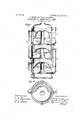
- Figure 1. is a central vertical section of apreferred form of tower; and Fig. 2 is a plan view of the same, partly in horizontal section.
- the absorption tower comprisesfa plurality of superposed absorption chambers a, a, a s'hownas three in number, assembledmsuch manner that the acking is. but of contact with the acid.
- the arrangement also ermits the gases to be completely absorbed 1n aliqu'id column of mimmum height, and therefore in a colu rm offering ,lthe nmin'nlm resistance to their ⁇ assage.”
- Thel'ateral'disposition ofthe perf orations is-also advantagpous as preventing 'violen't agitation of the 'quid surface,-and therefore avoiding the carrymg'of particles of the absorbing liquid from one compartment -to that next above.
- the inclination of this zone being such that the ascending absorbing liquid is directed outwardly as indicated by the arrows against the cooled walls.
- the cooling jackets e extend not only. around the absorption zone, but around the lower portions of de th t an those in the other 0 the several chamber walls, as shown, in order that the absorbing liquid may be cooled during substantially its entire course.
- the cover 0 the up or chamber is preferably of greater mbers, rovi ing thereby a deeper liquid co umn, w 'ch is efiective to absorb the final traces from the relatively dilute gases passing therethrough.
- the sizeand num er of the perforations should be such that their. aggregate area will substantially equal the area of the gas-inlet; as a more certain distribution of the gases is thereby secured.
- The. absorbing acid may be introduced into the up er chamber through a pipe f, flowing upwar through each chamber, and "passing between the several chambers through connecting pipes g extending between the upper walls.
- An absorption a paratus com rising a plurality of superposed absorption 0 ambers provided with cooling jackets, a central, upwardly-extending gas-inlet for each chamber, means foriritroducing gas' under pressure to said chambers, a cover for each inlet directing the gas in proximity to the chamber walls, erforations'in said cover in proximity to sai walls and inclined thereto, and means for establishing an upward current of liquid throu h each of said chambers.
- absorption a paratus comprising a plurality of superposed absorption provided with cooling jackets, a central, upwardly-extending gas-inlet for each chamber, means for introducing gas under pressure to said chambers, a cover for each inlet directing the ,gas in proximity to the chamber Wall's, aplurality of rows of staggered perforations in said cover in proximity to said wallsand inclined thereto, and means for establishing an n ward current, of liquid through each of said chambers.
Landscapes
- Chemical & Material Sciences (AREA)
- Chemical Kinetics & Catalysis (AREA)
- Gas Separation By Absorption (AREA)
Description
G. ESOHELLMANN & A. HARMUTH. APPARATUS FOR ABSORPTION 0P GASES.
APPLICATION FILED JULY 27, 1907.
PATENTED JULY 28,1908.
' eEoac EsoHELLiiANN ANDYALBERT HARMUTH, OF ST, PETERSBURG, RUSSIh;
nrinn'n'rus s. 3 03 1 1: OF GASES,
Specification 01- Letters Patent.
' Application filed rui av, 1907'; Serial No; 335,934.
To all whom concern: r I
Be it known that we, GEORG ESOHELL-i MANN, a Britishsubject, and ALBERT HAR- .MUT H, a German subject, residing at St. Pe-
tersburg, Einpire of-Ru'ssia', have invented certainnew" and useful Improvements 'in- A ,paratus for theAbsorption of Gases, of W oh the following is a-specification. I
The object of this'inventiom is to providean apparatus forthe-absorption ofqgases in suita e solvents, theapparatus beingmore particularly intended for the absor tion of gaseous sulfuric anhydrid in a suitab e liquid,
- usually sulfuric acid.
In the towers commonly employed heretofore for the absorption of sulfuricanhydrid, the current of the gaseous su'lfurtrioxid is brought into contact with the absorbing liquid by exposing an extended surfaceo the liquid 'to the gases by permitting it to flow downward over a filling material disposed within a vertically arranged tower, the-current of gas rising through the same. Among the many disadvantages of this arran ement may benoted the tendency to the formation of channels throughwhich the acid' flows without contact with the gas; the great amount of s ace required for an' installation capable of a sorbing considerable'qua-ntities of sulfur trioxid; and the f act that it is im'-' practicable to-cool the absorbing liquid durmg the progress of the absorption, it being necessary to permit periods of absor tion to. alternate with cooling eriods. E orts tof cool the absorbing liqu'i by applying cooling means to the tower have not been practically successful, since the cooling means cannot be effectively applied to the interior of'the' filling material or to the liquid itself, 'and the resulting complication ofthe apparatus isdisproportionate to the 'resultss'ecured.
We have now found that the absorption of the gaseous sulfuric anh drid may bequickly and effectively accomp "she'd by conve 'ng the'gas under ressure through the absorbing liquid or .aci ually favorable results cannot be secured y conveying the gases through the liquid by suction. Under a suitable ressure however an intimate contact may he secured between the gas and the liquid bysubdividing the gas at the same time into small bubbles, and by-applyingthe cool ing means at the surfaces'of contact between the absorbing medium and the gas the condi-.
. pious for rapid "and complete absorption are fulfilled,
fatented Ju1y'28, 1908.
' p A form (if-apparatus constructed in accordance with our mvention is showninthe accompanying drawing, wherein:
"Figure 1. is a central vertical section of apreferred form of tower; and Fig. 2 is a plan view of the same, partly in horizontal section. Referring 'to the drawing, the absorption tower comprisesfa plurality of superposed absorption chambers a, a, a s'hownas three in number, assembledmsuch manner that the acking is. but of contact with the acid.
ach chamber .is rovided with a centrallby disposed, upward y surmounted 'by an inverted bowl-shaped 'cover'c, carried by supports 6 on the inner Wall ofthe tower and makingfa substantially extending gas-inlet ,j
tightjoint'therewith. The outer'and-lower the perforations eing preferably disposed in that'each gas bubble shall'detach itself freely "andrise 'to'the surface of the liquid column without merging the adjacent bubbles,
thereby securing very rapid absorption.
The arrangement also ermits the gases to be completely absorbed 1n aliqu'id column of mimmum height, and therefore in a colu rm offering ,lthe nmin'nlm resistance to their\ assage." Thel'ateral'disposition ofthe perf orationsis-also advantagpous as preventing 'violen't agitation of the 'quid surface,-and therefore avoiding the carrymg'of particles of the absorbing liquid from one compartment -to that next above.
' In order to secure the highest efficinc absorption itis necessary that the cool means should be applied directly to the abof mg, i
sorption zone This is accomplished in the apparatus shown by surrounding the several a sorption chambers a, a, a by cooling jackets e, and is aided by the inclinedposition of the perforated zone 11 of the cover a,
the inclination of this zone being such that the ascending absorbing liquid is directed outwardly as indicated by the arrows against the cooled walls. Preferably the cooling jackets e extend not only. around the absorption zone, but around the lower portions of de th t an those in the other 0 the several chamber walls, as shown, in order that the absorbing liquid may be cooled during substantially its entire course.
As indicated 1n the drawing the cover 0 the up or chamber is preferably of greater mbers, rovi ing thereby a deeper liquid co umn, w 'ch is efiective to absorb the final traces from the relatively dilute gases passing therethrough.
The smaller the perforations in the zones d,
the more perfect will be the distribution of the gases and the more rapid their absor tion.
It-ispreferred that the sizeand num er of the perforations should be such that their. aggregate area will substantially equal the area of the gas-inlet; as a more certain distribution of the gases is thereby secured.
The. absorbing acid may be introduced into the up er chamber through a pipe f, flowing upwar through each chamber, and "passing between the several chambers through connecting pipes g extending between the upper walls.
portion of one chamber and the lower portion of the chamber next below. In this case the density of the acid overflowing from the lowermost chamber through the pipe h will be controlled by, the densit of that introing the chamber wa s, and means for direct-L ing the absorbing liquid against said cooled 2. An absorption a paratusbomlprising a plurality of superpose absorption 0 ambers,
means forestablishin an upward currentof liquid in each of sai chambers, means for distributing the gas in contact with said rising a liquid, means for directing the absorbing liquid against the chamber walls, and means for cooling said walls.
3. An absorption a paratus corn rising a plurality of super ose absorption 0 ambers, a as inlet for eac chamber, a cover for each in et directing the gas in proximity to the chamber walls, means For cooling said walls,
,-. perforations insaid cover in proximity to said wallsand inclined thereto, and means for establishing an upward current of liquid through each of said chambers.
. 5. An absorption a paratus com rising a plurality of superposed absorption 0 ambers provided with cooling jackets, a central, upwardly-extending gas-inlet for each chamber, means foriritroducing gas' under pressure to said chambers, a cover for each inlet directing the gas in proximity to the chamber walls, erforations'in said cover in proximity to sai walls and inclined thereto, and means for establishing an upward current of liquid throu h each of said chambers.
6. absorption a paratus comprising a plurality of superposed absorption provided with cooling jackets, a central, upwardly-extending gas-inlet for each chamber, means for introducing gas under pressure to said chambers, a cover for each inlet directing the ,gas in proximity to the chamber Wall's, aplurality of rows of staggered perforations in said cover in proximity to said wallsand inclined thereto, and means for establishing an n ward current, of liquid through each of said chambers.
In testimony whereof, we affix our signatures in presence of two witnesses.
Witnesses:
N. D. FoMIN, AUG. Nronrs.
c ambers
Priority Applications (1)
| Application Number | Priority Date | Filing Date | Title |
|---|---|---|---|
| US38593407A US894792A (en) | 1907-07-27 | 1907-07-27 | Apparatus for absorption of gases. |
Applications Claiming Priority (1)
| Application Number | Priority Date | Filing Date | Title |
|---|---|---|---|
| US38593407A US894792A (en) | 1907-07-27 | 1907-07-27 | Apparatus for absorption of gases. |
Publications (1)
| Publication Number | Publication Date |
|---|---|
| US894792A true US894792A (en) | 1908-07-28 |
Family
ID=2963219
Family Applications (1)
| Application Number | Title | Priority Date | Filing Date |
|---|---|---|---|
| US38593407A Expired - Lifetime US894792A (en) | 1907-07-27 | 1907-07-27 | Apparatus for absorption of gases. |
Country Status (1)
| Country | Link |
|---|---|
| US (1) | US894792A (en) |
Cited By (2)
| Publication number | Priority date | Publication date | Assignee | Title |
|---|---|---|---|---|
| US3617033A (en) * | 1968-10-25 | 1971-11-02 | Teijin Ltd | Apparatus for continuous gas-liquid contact |
| US3957635A (en) * | 1971-05-14 | 1976-05-18 | National Institute Of Metallurgy | Contacting liquids and solids in countercurrent |
-
1907
- 1907-07-27 US US38593407A patent/US894792A/en not_active Expired - Lifetime
Cited By (2)
| Publication number | Priority date | Publication date | Assignee | Title |
|---|---|---|---|---|
| US3617033A (en) * | 1968-10-25 | 1971-11-02 | Teijin Ltd | Apparatus for continuous gas-liquid contact |
| US3957635A (en) * | 1971-05-14 | 1976-05-18 | National Institute Of Metallurgy | Contacting liquids and solids in countercurrent |
Similar Documents
| Publication | Publication Date | Title |
|---|---|---|
| US3997303A (en) | Liquid-gas phase separator having a perforated plate and mist eliminator pad | |
| US3378349A (en) | Apparatus for treating mixed-phase fluid reactants | |
| US5110325A (en) | Recycle spray gas-liquid contactor | |
| US4820456A (en) | Mass-transfer apparatus | |
| PL194793B1 (en) | Bubble column and use thereof | |
| ES2245089T3 (en) | VAPOR-LIQUID CHEMICAL REACTOR FILLED WITH PRE-COMPACTLY LIQUID | |
| US6227524B1 (en) | High speed mass transfer tray | |
| US2678199A (en) | Gas-liquid contact apparatus | |
| US3075752A (en) | Gas-liquid contact tower | |
| US2733054A (en) | Van ackeren | |
| US894792A (en) | Apparatus for absorption of gases. | |
| US3016234A (en) | Unitary collecting, distributing and supporting plate for stage washers | |
| US2568875A (en) | Spray-type absorption tower | |
| US4487727A (en) | Packing material for contacting towers | |
| CN111013178A (en) | Stepped liquid circulation bubble tower and method for dispersing gas | |
| US1893667A (en) | Apparatus for treating hydrocarbon and other gases and oils | |
| IT8224596A1 (en) | EQUIPMENT FOR LIQUID GAS CONTACT | |
| US2120256A (en) | Process and apparatus for gas and liquid contact | |
| US1419867A (en) | Scrubber | |
| US2137735A (en) | Apparatus for treating gases or vapors with liquids | |
| US855448A (en) | Apparatus for washing and cooling gas. | |
| US4759884A (en) | Apparatus for gas wet treatment | |
| KR100452407B1 (en) | tray of distillation tower | |
| US1624793A (en) | Contact apparatus | |
| US755705A (en) | Chemical absorption apparatus. |