US894591A - Semaphore-signal. - Google Patents
Semaphore-signal. Download PDFInfo
- Publication number
- US894591A US894591A US36358007A US1907363580A US894591A US 894591 A US894591 A US 894591A US 36358007 A US36358007 A US 36358007A US 1907363580 A US1907363580 A US 1907363580A US 894591 A US894591 A US 894591A
- Authority
- US
- United States
- Prior art keywords
- shaft
- casing
- contacts
- semaphore
- signal
- Prior art date
- Legal status (The legal status is an assumption and is not a legal conclusion. Google has not performed a legal analysis and makes no representation as to the accuracy of the status listed.)
- Expired - Lifetime
Links
Images

Classifications
-
- B—PERFORMING OPERATIONS; TRANSPORTING
- B61—RAILWAYS
- B61L—GUIDING RAILWAY TRAFFIC; ENSURING THE SAFETY OF RAILWAY TRAFFIC
- B61L1/00—Devices along the route controlled by interaction with the vehicle or vehicle train, e.g. pedals
- B61L1/20—Safety arrangements for preventing or indicating malfunction of the device, e.g. by leakage current, by lightning
Definitions
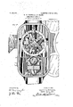
- Our invention relates to electrically-operated semaphore signals, and particularly to what is known as top-post signals in which the operating mechanlsm is inclosed in acasing surrounding the drive-shaft of the semaphore-arm, and its object is to reduce the size and cost of such signals. It has been customary heretofore in such si als to pro vide standards or brackets withln the casing inwhich the drive-shaft is journaled. These standards increase the size and add to the cost of the signal. It is ossible to journal the drive-shaft itself in the walls of the casing, but since this shaft ordinarily carries contacts cooperating with fixed contacts controlling the signal mechanism, theremoval ofthe standards removes the usual support for the fixed contacts.
- Our invention consists in su porting the fixed contacts on thedrive-sha t itself, and
- A represents an inclosing casing in which is mounted an electric motor B, which is connected through suitable speed-reducing gearing, not shown, to a drive-wheel O loosely mounted on the main drive-shaft D, which is 'ournaled in a stud or boss D in the wall of t e casing, and carries the semaphore-arm E and its counter-Wei ht E.
- a suitable clutch or slot mechan: ism comprising magnet-coils F and a locking piece G controlled thereby and of t e drive-w eel C.
- contacts H are mounted on the shaft D. These contacts are carried on insulating studs h projecting from a collar H, which is secured to shaft D by a set screw as shown in Fig. 1.
- a sleeve I is placed on the shaft D carrgng contacts J cooperating with the contac NH on the shaft. To avoid complicating the drawin the connections of these. contacts are omltted since the particular connections employed form no part of our invention.
- an arm K is provided, which engages the casing.
- a pin L rejecting from the casing is provided, and t e end of the arm K is formed with a socket into which the end of the pin L enters.
- a casin a shaft journaled in said casing, a semap ore-arm carried by said shaft, electric operatin mechanism in said casing for driving sai shaft, contacts fixed on said shaft for controlling said mechanism, a sleeve on said shaft, means for preventing rotation of said sleeve, and contacts carried by said sleeve cooperating with the first-mentioned contacts.
- a semaphore signal a casing, a shaft journaled in said casing, a semaphore-arm carried by said shaft, electric operating mechanism in said casing for driving said 5 shaft, contacts fixed on said shaft for controlling said mechanism, a sleeve on said shaft, an arm extending from said sleeve and engaging said casing, and contacts carried by said sleeve cooperating with the first-mentioned contacts.
- a semaphore signal a casing, a shaft journaled in said casing, a semaphore-arm 1 carried by said shaft, electric operating mechanism in said casing for drivlng said 15 shaft, contacts fixed on said shaft for controlling said mechanism, a sleeve on said shaft, an arm extending from said sleeve, said arm and said casing being provided one with a socket and the other wlth a projection adapted to enter said socket, and con- 20 tacts carried by said sleeve cooperating with the first-mentioned contacts.
Description
110,894,591. PATENTED JULY 28, 1908.
w. w. BROWN & A. G. CLARK.
'SEMAPHORE SIGNAL.
APPLICATION FILED MAR. 21, 1907."
W|TNE55E5 I INVENTEIR'S WALTERWEIREIWN I W.ELARK.
bu NULL] 2 SHEETS-SHEET 1.
PATENTED JULY 28, 1908.
2 SHEETS-SHEET 2.
INVENTEIRS v \A/ALTER'W Emuvvm.
W. W. BROWN & A. G. CLARK. I
S'BMAPHORE SIGNAL.
APPLIUATION FILED MAR. 21 1907.
me: mill 1 ,7 llilmmn mm'riimuim I AR A G. CLARK.
' R M Attq UNITED STATES PATENT OFFICE.
WALTER W. BROWN AND ARBA G. CLARK, OF SOHENEGTADY, NEW YORK, ASSIGNORS TO GENERAL ELECTRIC COMPANY, A CORPORATION OF NEW YORK.
SEMAPHORE-SIGNAL.
x v Specification of Letters Patent. Application filed March 21, 1907. Serial No. 363,580.
Patented. July'28, 1908.
To all whom it may concern:
Be it known that WG,-WALTER W. BROWN and ARBA G. CLARK, citizens of the United States, residing at Schenectady, county of Schenectady, State of New York, have invented certain new and useful Improvements in Semaphore-Signals, of which the following is a specification.
Our invention relates to electrically-operated semaphore signals, and particularly to what is known as top-post signals in which the operating mechanlsm is inclosed in acasing surrounding the drive-shaft of the semaphore-arm, and its object is to reduce the size and cost of such signals. It has been customary heretofore in such si als to pro vide standards or brackets withln the casing inwhich the drive-shaft is journaled. These standards increase the size and add to the cost of the signal. It is ossible to journal the drive-shaft itself in the walls of the casing, but since this shaft ordinarily carries contacts cooperating with fixed contacts controlling the signal mechanism, theremoval ofthe standards removes the usual support for the fixed contacts.
Our invention consists in su porting the fixed contacts on thedrive-sha t itself, and
providing suitable means for preventing their rotation; thereby V rendering possible the complete elimination of standards or brackets. Y 1 I a Our invention will best be understood by reference to the acco panying drawings, in which 7 Figure 1 shows a side elevation, with the casing partly broken away, of a semaphore signal arranged in accordance with our invention; and Fig. 2 shows a back elevation of the same with the coverof the casing removed. v
In the drawings, A represents an inclosing casing in which is mounted an electric motor B, which is connected through suitable speed-reducing gearing, not shown, to a drive-wheel O loosely mounted on the main drive-shaft D, which is 'ournaled in a stud or boss D in the wall of t e casing, and carries the semaphore-arm E and its counter-Wei ht E. In orderto clutch the drive-wheel t0 the shaft D, a suitable clutch or slot mechan: ism is provided comprising magnet-coils F and a locking piece G controlled thereby and of t e drive-w eel C. When the coils are adapted to en age studs O on the perig hery energized, the locking piece G is thrust outward into thepath of the studs C, as shown in the drawings. When'the magnets are deenergized, their armature falls away, withdrawing the locking piece G from engagement with the studs; I
For controlling the motor B and magnets F, contacts H are mounted on the shaft D. These contacts are carried on insulating studs h projecting from a collar H, which is secured to shaft D by a set screw as shown in Fig. 1. A sleeve I is placed on the shaft D carrgng contacts J cooperating with the contac NH on the shaft. To avoid complicating the drawin the connections of these. contacts are omltted since the particular connections employed form no part of our invention. To revent rotation of the sleeve which carries t e cont-acts J, an arm K is provided, which engages the casing. For this purpose a pin L rejecting from the casing is provided, and t e end of the arm K is formed with a socket into which the end of the pin L enters. By means of this construction the contacts J are supported in position without requiring any standards or brackets for this purpose, and the construction is such that the cont-acts may readily be removed.
We do. not desire to limit ourselves to the particular construction and arrangement of parts here shown, but aim in the appended claims to cover all modifications ich are within the scope of our invention.
'What we claim as new andv desire to secure by Letters Patentof the United States, is,
1..In a semaphore signal, a casing, a shaft journaled. in said casing, a semaphore-arm carried by said shaft, electric operating mechanism in said casing for driving said shaft, contacts fixed on said shaft for controlling. said mechanism, contacts loosely mounted on said shaft cooperating with the,
first-mentioned contacts, and means forpreventing rotation of said loosely mounted contacts.
'2. In asemaphore signal, a casin a shaft journaled in said casing, a semap ore-arm carried by said shaft, electric operatin mechanism in said casing for driving sai shaft, contacts fixed on said shaft for controlling said mechanism, a sleeve on said shaft, means for preventing rotation of said sleeve, and contacts carried by said sleeve cooperating with the first-mentioned contacts.
3. In a semaphore signal, a casing, a shaft journaled in said casing, a semaphore-arm carried by said shaft, electric operating mechanism in said casing for driving said 5 shaft, contacts fixed on said shaft for controlling said mechanism, a sleeve on said shaft, an arm extending from said sleeve and engaging said casing, and contacts carried by said sleeve cooperating with the first-mentioned contacts. 3
4. In a semaphore signal, a casing, a shaft journaled in said casing, a semaphore-arm 1 carried by said shaft, electric operating mechanism in said casing for drivlng said 15 shaft, contacts fixed on said shaft for controlling said mechanism, a sleeve on said shaft, an arm extending from said sleeve, said arm and said casing being provided one with a socket and the other wlth a projection adapted to enter said socket, and con- 20 tacts carried by said sleeve cooperating with the first-mentioned contacts.
In witness whereof, we have hereunto set our hands this 20thday of March, 1907.
WALTER w. BROWN. ARBA e. (,LARK.
Witnesses:
BENJAMIN B. HULL, HELEN ORFORD.
Priority Applications (1)
| Application Number | Priority Date | Filing Date | Title |
|---|---|---|---|
| US36358007A US894591A (en) | 1907-03-21 | 1907-03-21 | Semaphore-signal. |
Applications Claiming Priority (1)
| Application Number | Priority Date | Filing Date | Title |
|---|---|---|---|
| US36358007A US894591A (en) | 1907-03-21 | 1907-03-21 | Semaphore-signal. |
Publications (1)
| Publication Number | Publication Date |
|---|---|
| US894591A true US894591A (en) | 1908-07-28 |
Family
ID=2963018
Family Applications (1)
| Application Number | Title | Priority Date | Filing Date |
|---|---|---|---|
| US36358007A Expired - Lifetime US894591A (en) | 1907-03-21 | 1907-03-21 | Semaphore-signal. |
Country Status (1)
| Country | Link |
|---|---|
| US (1) | US894591A (en) |
-
1907
- 1907-03-21 US US36358007A patent/US894591A/en not_active Expired - Lifetime
Similar Documents
| Publication | Publication Date | Title |
|---|---|---|
| US894591A (en) | Semaphore-signal. | |
| US1038278A (en) | Semaphore-signal. | |
| US917003A (en) | Semaphore-signal. | |
| US965671A (en) | Reversing-switch. | |
| US808226A (en) | Controller for magnetic clutches. | |
| US777857A (en) | Dynamo for train-lighting. | |
| US1261985A (en) | Hall-button-cut-out switch. | |
| US654130A (en) | Electric steering-gear. | |
| US463585A (en) | Walter b | |
| US727411A (en) | Alternating-current motor. | |
| US1352081A (en) | Signaling system | |
| US524385A (en) | Controller for electric motors | |
| US1425890A (en) | Wilbur l | |
| US460541A (en) | Electric elevator | |
| US665319A (en) | Alarm device for armature-shafts. | |
| US933956A (en) | Electrical switch. | |
| US1252826A (en) | Vibratory actuator. | |
| US791536A (en) | Driving mechanism for cash-registers. | |
| US568608A (en) | Island | |
| US1025140A (en) | Potential switch. | |
| US841874A (en) | Rotary current-motor connected in cascade system. | |
| US827322A (en) | Distant control of electric motors. | |
| US1097208A (en) | Electric switch. | |
| US560766A (en) | In opposite dlrec | |
| US142688A (en) | Improvement in electrica-l regulators for transmitting-instruments |