US8944717B2 - Integrated pivot pin lubricator - Google Patents
Integrated pivot pin lubricator Download PDFInfo
- Publication number
- US8944717B2 US8944717B2 US13/693,373 US201213693373A US8944717B2 US 8944717 B2 US8944717 B2 US 8944717B2 US 201213693373 A US201213693373 A US 201213693373A US 8944717 B2 US8944717 B2 US 8944717B2
- Authority
- US
- United States
- Prior art keywords
- pin
- hinge
- lubrication
- path
- port
- Prior art date
- Legal status (The legal status is an assumption and is not a legal conclusion. Google has not performed a legal analysis and makes no representation as to the accuracy of the status listed.)
- Active, expires
Links
- 238000005461 lubrication Methods 0.000 claims abstract description 64
- 239000012530 fluid Substances 0.000 claims abstract description 12
- 238000004891 communication Methods 0.000 claims abstract description 7
- 239000000314 lubricant Substances 0.000 claims description 11
- 230000008878 coupling Effects 0.000 claims description 9
- 238000010168 coupling process Methods 0.000 claims description 9
- 238000005859 coupling reaction Methods 0.000 claims description 9
- 230000037361 pathway Effects 0.000 description 14
- 238000003466 welding Methods 0.000 description 3
- 241001124569 Lycaenidae Species 0.000 description 2
- 230000000712 assembly Effects 0.000 description 2
- 238000000429 assembly Methods 0.000 description 2
- 238000000034 method Methods 0.000 description 2
- 230000006978 adaptation Effects 0.000 description 1
- 238000002485 combustion reaction Methods 0.000 description 1
- 238000012423 maintenance Methods 0.000 description 1
- 238000012545 processing Methods 0.000 description 1
Images


Classifications
-
- E—FIXED CONSTRUCTIONS
- E02—HYDRAULIC ENGINEERING; FOUNDATIONS; SOIL SHIFTING
- E02F—DREDGING; SOIL-SHIFTING
- E02F9/00—Component parts of dredgers or soil-shifting machines, not restricted to one of the kinds covered by groups E02F3/00 - E02F7/00
- E02F9/20—Drives; Control devices
- E02F9/22—Hydraulic or pneumatic drives
- E02F9/2264—Arrangements or adaptations of elements for hydraulic drives
- E02F9/2275—Hoses and supports therefor and protection therefor
-
- B—PERFORMING OPERATIONS; TRANSPORTING
- B25—HAND TOOLS; PORTABLE POWER-DRIVEN TOOLS; MANIPULATORS
- B25J—MANIPULATORS; CHAMBERS PROVIDED WITH MANIPULATION DEVICES
- B25J17/00—Joints
-
- B—PERFORMING OPERATIONS; TRANSPORTING
- B25—HAND TOOLS; PORTABLE POWER-DRIVEN TOOLS; MANIPULATORS
- B25J—MANIPULATORS; CHAMBERS PROVIDED WITH MANIPULATION DEVICES
- B25J18/00—Arms
-
- E—FIXED CONSTRUCTIONS
- E02—HYDRAULIC ENGINEERING; FOUNDATIONS; SOIL SHIFTING
- E02F—DREDGING; SOIL-SHIFTING
- E02F9/00—Component parts of dredgers or soil-shifting machines, not restricted to one of the kinds covered by groups E02F3/00 - E02F7/00
- E02F9/006—Pivot joint assemblies
-
- F—MECHANICAL ENGINEERING; LIGHTING; HEATING; WEAPONS; BLASTING
- F01—MACHINES OR ENGINES IN GENERAL; ENGINE PLANTS IN GENERAL; STEAM ENGINES
- F01M—LUBRICATING OF MACHINES OR ENGINES IN GENERAL; LUBRICATING INTERNAL COMBUSTION ENGINES; CRANKCASE VENTILATING
- F01M11/00—Component parts, details or accessories, not provided for in, or of interest apart from, groups F01M1/00 - F01M9/00
-
- F—MECHANICAL ENGINEERING; LIGHTING; HEATING; WEAPONS; BLASTING
- F16—ENGINEERING ELEMENTS AND UNITS; GENERAL MEASURES FOR PRODUCING AND MAINTAINING EFFECTIVE FUNCTIONING OF MACHINES OR INSTALLATIONS; THERMAL INSULATION IN GENERAL
- F16C—SHAFTS; FLEXIBLE SHAFTS; ELEMENTS OR CRANKSHAFT MECHANISMS; ROTARY BODIES OTHER THAN GEARING ELEMENTS; BEARINGS
- F16C11/00—Pivots; Pivotal connections
- F16C11/04—Pivotal connections
- F16C11/045—Pivotal connections with at least a pair of arms pivoting relatively to at least one other arm, all arms being mounted on one pin
-
- F—MECHANICAL ENGINEERING; LIGHTING; HEATING; WEAPONS; BLASTING
- F16—ENGINEERING ELEMENTS AND UNITS; GENERAL MEASURES FOR PRODUCING AND MAINTAINING EFFECTIVE FUNCTIONING OF MACHINES OR INSTALLATIONS; THERMAL INSULATION IN GENERAL
- F16C—SHAFTS; FLEXIBLE SHAFTS; ELEMENTS OR CRANKSHAFT MECHANISMS; ROTARY BODIES OTHER THAN GEARING ELEMENTS; BEARINGS
- F16C33/00—Parts of bearings; Special methods for making bearings or parts thereof
- F16C33/02—Parts of sliding-contact bearings
- F16C33/04—Brasses; Bushes; Linings
- F16C33/06—Sliding surface mainly made of metal
- F16C33/10—Construction relative to lubrication
- F16C33/1025—Construction relative to lubrication with liquid, e.g. oil, as lubricant
- F16C33/106—Details of distribution or circulation inside the bearings, e.g. details of the bearing surfaces to affect flow or pressure of the liquid
- F16C33/1085—Channels or passages to recirculate the liquid in the bearing
-
- F—MECHANICAL ENGINEERING; LIGHTING; HEATING; WEAPONS; BLASTING
- F16—ENGINEERING ELEMENTS AND UNITS; GENERAL MEASURES FOR PRODUCING AND MAINTAINING EFFECTIVE FUNCTIONING OF MACHINES OR INSTALLATIONS; THERMAL INSULATION IN GENERAL
- F16C—SHAFTS; FLEXIBLE SHAFTS; ELEMENTS OR CRANKSHAFT MECHANISMS; ROTARY BODIES OTHER THAN GEARING ELEMENTS; BEARINGS
- F16C2350/00—Machines or articles related to building
- F16C2350/26—Excavators
-
- Y—GENERAL TAGGING OF NEW TECHNOLOGICAL DEVELOPMENTS; GENERAL TAGGING OF CROSS-SECTIONAL TECHNOLOGIES SPANNING OVER SEVERAL SECTIONS OF THE IPC; TECHNICAL SUBJECTS COVERED BY FORMER USPC CROSS-REFERENCE ART COLLECTIONS [XRACs] AND DIGESTS
- Y10—TECHNICAL SUBJECTS COVERED BY FORMER USPC
- Y10T—TECHNICAL SUBJECTS COVERED BY FORMER US CLASSIFICATION
- Y10T403/00—Joints and connections
- Y10T403/32—Articulated members
- Y10T403/32606—Pivoted
- Y10T403/32861—T-pivot, e.g., wrist pin, etc.
- Y10T403/32885—Expanded pin or end
-
- Y—GENERAL TAGGING OF NEW TECHNOLOGICAL DEVELOPMENTS; GENERAL TAGGING OF CROSS-SECTIONAL TECHNOLOGIES SPANNING OVER SEVERAL SECTIONS OF THE IPC; TECHNICAL SUBJECTS COVERED BY FORMER USPC CROSS-REFERENCE ART COLLECTIONS [XRACs] AND DIGESTS
- Y10—TECHNICAL SUBJECTS COVERED BY FORMER USPC
- Y10T—TECHNICAL SUBJECTS COVERED BY FORMER US CLASSIFICATION
- Y10T403/00—Joints and connections
- Y10T403/32—Articulated members
- Y10T403/32606—Pivoted
- Y10T403/32861—T-pivot, e.g., wrist pin, etc.
- Y10T403/32918—T-pivot, e.g., wrist pin, etc. fork and tongue
-
- Y—GENERAL TAGGING OF NEW TECHNOLOGICAL DEVELOPMENTS; GENERAL TAGGING OF CROSS-SECTIONAL TECHNOLOGIES SPANNING OVER SEVERAL SECTIONS OF THE IPC; TECHNICAL SUBJECTS COVERED BY FORMER USPC CROSS-REFERENCE ART COLLECTIONS [XRACs] AND DIGESTS
- Y10—TECHNICAL SUBJECTS COVERED BY FORMER USPC
- Y10T—TECHNICAL SUBJECTS COVERED BY FORMER US CLASSIFICATION
- Y10T403/00—Joints and connections
- Y10T403/32—Articulated members
- Y10T403/32606—Pivoted
- Y10T403/32951—Transverse pin or stud
Definitions
- the present disclosure relates to lubrication of pivot pins of work machines and, more particularly, to lubrication of pivot pins via internal lubrication paths.
- an operator may use a tree harvester having a harvester head moveably coupled to a wheeled or tracked chassis via a boom assembly.
- other work machines also include boom assemblies.
- Such boom assemblies include multiple boom sections (or arms) that are pivotably mounted to each other via pivot pins.
- hydraulic cylinders are coupled to boom sections via pivot pins. Due to the relative movement of the boom arms and their pivot pins, such connections are lubricated to reduce wear and increase part life.
- the boom arms can be positioned such that access to the locations needing lubrication can be onerous. Additionally, manual lubrication requires that the work machine be taken out of service for a portion of time while such lubrication maintenance is performed.
- the present disclosure provides a hinge on a work machine.
- the hinge includes a first member such as a first boom arm and a second member such as a second boom arm.
- the hinge further includes a pin hingedly linking the first and second members.
- the pin has a path therein having a first portion that extends axially.
- the hinge further includes a port in fluid communication with the path. The port is radially offset by a fixed distance and fixed orientation from the first portion within the pin.
- a hinge lubrication apparatus including a first hinge member, a second hinge member, a hinge pin operable to hingedly couple the first and second members, and a lubricant supply path.
- the hinge pin has a lubrication path therein.
- the lubricant supply duct is operable to supply lubricant to the lubrication path via a connection port fixed to the first hinge member that is in fluid communication with the lubrication path.
- the connection port is positioned such that connection thereto by the lubricant supply duct is on an interior of the first hinge member.
- a hinge pin including a pin body and a second body.
- the second body having a first portion axially aligned with the pin body; a second portion radially displaced relative to the first portion; and a lubrication path that extends from the first portion to the second portion.
- a hinge lubrication apparatus for a work machine including a first hinge member, a second hinge member operably coupled to a work machine cab via the first hinge member; a hinge pin operable to hingedly couple the first and second members; and a lubrication path including a lubrication port fixed to the first hinge member, a first portion within the hinge pin, and a second portion extending between the lubrication port and the first portion; the second portion defining a rigid path.
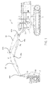
- FIG. 1 is a side elevational view of a harvester of the present disclosure, the harvester having a tracked chassis and a harvester head moveably coupled to the chassis via a hinged boom;
- FIG. 2 is a partially transparent perspective view of a hinge pin of a hinge of the harvester of FIG. 1 showing internal lubrication passages;
- FIG. 3 is a bottom perspective view of the hinge employing the hinge pin of FIG. 2 .
- a tracked harvester 10 of the present disclosure illustratively includes a carrier or chassis 12 and an operator cab 14 that houses and protects the operator of harvester 10 .
- Operator cab 14 may include foot pedals, a steering wheel, joysticks, monitors, and other controls (not shown) for operating harvester 10 .
- Harvester 10 also includes engine 16 .
- Engine 16 may be in the form of an internal combustion engine or an electric engine, for example.
- Harvester 10 further includes a plurality of traction devices, illustratively ground-engaging tracks 18 , for supporting chassis 12 above the ground. In use, engine 16 drives tracks 18 to propel chassis 12 of harvester 10 across the ground.
- harvester 10 is shown and described herein using tracks 18 as the fraction devices, it is within the scope of the present disclosure that other types of harvesters 10 may be used, such as wheeled harvesters that use wheels as the traction devices.
- the present disclosure is described in the environment of a harvester, it should be appreciated that the concepts can be applied to work machines with articulation points generally.
- Harvester 10 still further includes a forward-mounted harvester head 20 that is configured to fell and process trees.
- Head 20 is moveably coupled to chassis 12 via boom assembly 22 , which enables head 20 to be raised, lowered, and tilted relative to chassis 12 to position head 20 at a desired position relative to a tree to be felled.
- First and second hydraulic boom cylinders 24 a , 24 b are shown in FIG. 1 for moving boom assembly 22 relative to chassis 12 .
- Head 20 is also moveably coupled to support arm 26 of boom assembly 22 . For example, as shown in FIG.
- head 20 may be positioned upright or vertically on support arm 26 to fell a tree, and then head 20 may be tipped downward or horizontally relative to support arm 26 about axis 28 for further processing of the felled tree, including delimbing and chopping operations.
- a third hydraulic boom cylinder (not shown) may be provided for moving head 20 about axis 28 relative to support arm 26 of boom assembly 22 .
- Boom assembly 22 includes first arm 30 and second arm 32 in addition to the previously mentioned cylinders 24 a , 24 b .
- Each of first arm 30 , second arm 32 , support arm 26 , and cylinders 24 a , 24 b are coupled together at connection points 40 a - e .
- Connection points 40 a - e each include pins 50 that engage voids defined in the respective parts 30 , 32 , 26 , 24 a , 24 b . Accordingly, with respect to the hinges formed, first arm 30 , second arm 32 , support arm 26 , and cylinders 24 a , 24 b all act as hinge members that are hingedly coupled by pins 50 .
- each pin 50 includes cylindrical bearing member 52 , flag 54 , and lubrication port 56 .
- Pin 50 further includes an internal lubrication pathway 57 .
- Cylindrical bearing member 52 includes first portion 58 of lubrication pathway 57 .
- First portion 58 extends radially from an internal point 60 to the outer surface creating two exit points 62 .
- Internal point 60 provides an interface with second portion 64 of lubrication pathway 57 that extends axially from internal point 60 to an axial end 66 of cylindrical bearing member 52 .
- Flag 54 provides for coupling pin 50 to arm 30 .
- Flag 54 includes coupling plate 68 and pathway plate 70 .
- Coupling plate 68 includes bearing aperture 72 , port aperture 74 , and bolt aperture 76 .
- Coupling plate 68 is fixedly secured to cylindrical bearing member 52 such as by welding cylindrical bearing member 52 within bearing aperture 72 or welding such that an end of cylindrical bearing member 52 abuts coupling plate 68 .
- Pathway plate 70 includes a third portion 78 of lubrication pathway 57 therein. Pathway plate 70 is coupled to coupling plate 68 , such as by welding, such that third portion 78 of lubrication pathway 57 is formed therebetween with at least one wall of third portion 78 being defined by coupling plate 68 .
- Third portion 78 extends from axial end 66 of cylindrical bearing member 52 to port aperture 74 .
- Bolt aperture 76 is positioned, sized, and shaped to receive bolt 84 therethrough to secure pin 50 to arm 26 as shown in FIG. 3 .
- Lubrication port 56 is disposed in an aperture in wall 86 of arm 30 so as to align with port aperture 74 .
- the combination of port aperture 74 , the aperture in wall 86 , and lubrication port 56 provide fourth portion 82 of lubrication pathway 57 to place an input of lubrication port 56 in fluid connection with lubrication pathway 57 .
- Lubrication port 56 includes a threaded interface such that port 56 is able to threadably receive lubrication duct 80 . Accordingly, lubrication duct 80 is able to supply lubricant, via lubrication pathway 57 , to surface points 62 of cylindrical bearing member 52 .
- lubrication port 56 provides a right-angle adapter such that lubrication duct 80 runs parallel to wall 86 of arm 30 .
- the right-angle adapter is part of duct 80 such that lubrication port 56 is substantially straight.
- second portion 64 extends axially along a center of cylindrical bearing member 52 .
- second portion 64 is offset from the center of cylindrical bearing member 52 .
- Third portion 78 extends perpendicularly to second portion 64 and radially relative to cylindrical bearing member 52 .
- Third portion 78 is further shown as being parallel to first portion 58 .
- Fourth portion 82 is illustratively perpendicular to third portion 78 , parallel to second portion 64 , and perpendicular to first portion 58 .
- internal lubrication pathway 57 has portions extending perpendicularly to each other, embodiments are envisioned where portions extend at non-right angles relative to each other. Such angles can be chosen to achieve desired flow characteristics.
- first hydraulic boom cylinders 24 a When pin 50 is coupled to first arm 30 , first hydraulic boom cylinders 24 a , or other connection points 40 a , lubrication port 56 is disposed on an interior surface of first arm 30 (or other arm to which connection is being supplied). Accordingly, the walls of first arm 30 provide some protection for lubrication duct 80 .
- internal lubrication pathway 57 provides for a fixed connection point on a hinge member (arm 30 ) that is able to supply lubrication to pin 50 via the interior of cylindrical bearing member 52 . Furthermore, the fixed connection point provides that portions of the lubrication pathway (from supply reservoir, not shown, to exit points 62 ) is able to be located in positions that are protected, either by walls 86 of arms 30 or otherwise.
Landscapes
- Engineering & Computer Science (AREA)
- General Engineering & Computer Science (AREA)
- Mechanical Engineering (AREA)
- Robotics (AREA)
- Mining & Mineral Resources (AREA)
- Oil, Petroleum & Natural Gas (AREA)
- Chemical & Material Sciences (AREA)
- Civil Engineering (AREA)
- Structural Engineering (AREA)
- Pivots And Pivotal Connections (AREA)
- Tents Or Canopies (AREA)
- Carbon Steel Or Casting Steel Manufacturing (AREA)
- Jib Cranes (AREA)
Abstract
Description
Claims (22)
Priority Applications (8)
| Application Number | Priority Date | Filing Date | Title |
|---|---|---|---|
| US13/693,373 US8944717B2 (en) | 2012-12-04 | 2012-12-04 | Integrated pivot pin lubricator |
| PCT/US2013/024146 WO2014088609A1 (en) | 2012-12-04 | 2013-01-31 | Boom apparatus with protective barrier for flexible line |
| CA2893693A CA2893693C (en) | 2012-12-04 | 2013-01-31 | Boom apparatus with protective barrier for flexible line |
| US14/646,187 US9458606B2 (en) | 2012-12-04 | 2013-01-31 | Boom apparatus with protective barrier for flexible line |
| BR112015012421A BR112015012421A2 (en) | 2012-12-04 | 2013-01-31 | boom device |
| AU2013356683A AU2013356683A1 (en) | 2012-12-04 | 2013-01-31 | Boom apparatus with protective barrier for flexible line |
| CA2832928A CA2832928A1 (en) | 2012-12-04 | 2013-11-13 | Integrated pivot pin lubricator |
| CN201310646429.3A CN103843533A (en) | 2012-12-04 | 2013-12-04 | Integrated pivot pin lubricator |
Applications Claiming Priority (1)
| Application Number | Priority Date | Filing Date | Title |
|---|---|---|---|
| US13/693,373 US8944717B2 (en) | 2012-12-04 | 2012-12-04 | Integrated pivot pin lubricator |
Related Child Applications (1)
| Application Number | Title | Priority Date | Filing Date |
|---|---|---|---|
| US14/646,187 Continuation US9458606B2 (en) | 2012-12-04 | 2013-01-31 | Boom apparatus with protective barrier for flexible line |
Publications (2)
| Publication Number | Publication Date |
|---|---|
| US20140153997A1 US20140153997A1 (en) | 2014-06-05 |
| US8944717B2 true US8944717B2 (en) | 2015-02-03 |
Family
ID=50825596
Family Applications (2)
| Application Number | Title | Priority Date | Filing Date |
|---|---|---|---|
| US13/693,373 Active 2033-01-27 US8944717B2 (en) | 2012-12-04 | 2012-12-04 | Integrated pivot pin lubricator |
| US14/646,187 Active US9458606B2 (en) | 2012-12-04 | 2013-01-31 | Boom apparatus with protective barrier for flexible line |
Family Applications After (1)
| Application Number | Title | Priority Date | Filing Date |
|---|---|---|---|
| US14/646,187 Active US9458606B2 (en) | 2012-12-04 | 2013-01-31 | Boom apparatus with protective barrier for flexible line |
Country Status (6)
| Country | Link |
|---|---|
| US (2) | US8944717B2 (en) |
| CN (1) | CN103843533A (en) |
| AU (1) | AU2013356683A1 (en) |
| BR (1) | BR112015012421A2 (en) |
| CA (2) | CA2893693C (en) |
| WO (1) | WO2014088609A1 (en) |
Cited By (4)
| Publication number | Priority date | Publication date | Assignee | Title |
|---|---|---|---|---|
| US9587375B2 (en) * | 2015-04-06 | 2017-03-07 | CNC Industries Ltd. | Bucket of a rope shovel |
| US20220178109A1 (en) * | 2019-03-08 | 2022-06-09 | Caterpillar Sarl | Grease feeding piping arrangement structure in construction machine |
| US20220290710A1 (en) * | 2019-09-02 | 2022-09-15 | Kobelco Construction Machinery Co., Ltd. | Structure unit |
| US20240200720A1 (en) * | 2019-08-27 | 2024-06-20 | Caterpillar Global Mining Llc | Fluid distribution assembly |
Families Citing this family (10)
| Publication number | Priority date | Publication date | Assignee | Title |
|---|---|---|---|---|
| US9706707B2 (en) * | 2015-09-24 | 2017-07-18 | Macdon Industries Ltd. | Crop harvesting machine with a header separable from a tractor |
| CN108547853A (en) * | 2018-03-02 | 2018-09-18 | 苏州市昌星模具机械有限公司 | High-precision high rigidity connecting pin and its manufacturing process applied to Landing Gear System |
| JP7193238B2 (en) * | 2018-03-20 | 2022-12-20 | 株式会社竹内製作所 | Greasing system for construction machine and method for greasing construction machine |
| JP6934459B2 (en) * | 2018-09-11 | 2021-09-15 | 日立建機株式会社 | Construction machinery |
| US11459727B2 (en) * | 2019-06-26 | 2022-10-04 | Caterpillar Global Mining Llc | Coupling assembly for a machine |
| CN111745664A (en) * | 2020-06-30 | 2020-10-09 | 京良(广州)科技股份有限公司 | A pallet robot with information traceability structure |
| CN112213858B (en) * | 2020-09-30 | 2022-06-14 | Oppo广东移动通信有限公司 | Spindle mechanism and glasses |
| US12163623B2 (en) * | 2022-02-03 | 2024-12-10 | Caterpillar Inc. | Automatic lubrication system for kinematic linkage |
| CN115123049B (en) * | 2022-03-09 | 2024-09-27 | 德明尚品科技集团有限公司 | Pull arm type self-loading and unloading carriage |
| US12276081B2 (en) * | 2022-06-06 | 2025-04-15 | Caterpillar Inc. | Lubrication distribution system for machine with kinematic linkages |
Citations (31)
| Publication number | Priority date | Publication date | Assignee | Title |
|---|---|---|---|---|
| US1923717A (en) * | 1932-12-22 | 1933-08-22 | Ingersoll Rand Co | Oiling device |
| US1999394A (en) * | 1932-11-19 | 1935-04-30 | Chrysler Corp | Front axle construction |
| US2439569A (en) * | 1944-09-09 | 1948-04-13 | Curtiss Wright Corp | Universal joint |
| US2726107A (en) * | 1953-12-21 | 1955-12-06 | Oscar R Kasten | Automatic take-up for pivot pin connections |
| US2847238A (en) * | 1954-12-03 | 1958-08-12 | Exxon Research Engineering Co | Pin retainer |
| US3295699A (en) | 1964-08-28 | 1967-01-03 | Jr John P Bauernschub | Folding boom assembly |
| US3616940A (en) | 1970-03-30 | 1971-11-02 | Baker Equipment Eng Co | Boom structure for utility trucks and the like |
| US4260064A (en) | 1977-12-12 | 1981-04-07 | Trac-Back Corporation | Crane attachments for backhoe and tractor |
| US4398862A (en) * | 1982-02-22 | 1983-08-16 | Dresser Industries, Inc. | Pivot pin assembly |
| US4607977A (en) * | 1985-08-05 | 1986-08-26 | Varnelis Edmund K | Pivot joint |
| US4609322A (en) * | 1984-08-13 | 1986-09-02 | Caterpillar Tractor Co. | Mounting for a linkage arrangement |
| US4711614A (en) * | 1985-02-24 | 1987-12-08 | Caterpillar Industrial Inc. | Lift mast mounting arrangement and method for removal |
| US4858962A (en) * | 1986-03-15 | 1989-08-22 | Thyssen Industrie Ag | Articulated joint |
| US4923320A (en) * | 1987-06-19 | 1990-05-08 | Gelenkwellenbau Gmbh | Disengageable coupling |
| US4961667A (en) * | 1989-09-05 | 1990-10-09 | Caterpillar Inc. | Pivot joint for loader linkages and the like |
| US5211484A (en) * | 1988-11-02 | 1993-05-18 | Quaglia Lawrence D | Pressure regulated lubricating system for bearings |
| US5601161A (en) * | 1994-03-31 | 1997-02-11 | Brigden; Alex | Snubber brake assembly |
| US5769557A (en) * | 1996-07-12 | 1998-06-23 | Caterpillar Inc. | Sealed pin joint assembly |
| US5806313A (en) | 1995-11-30 | 1998-09-15 | Caterpillar Inc. | Conduit arrangement for a construction machine |
| US6135242A (en) * | 1996-06-03 | 2000-10-24 | Mr. Safety-Check Systems, Inc. | Braking system for a vehicle having a stroke indicator |
| US6322280B1 (en) | 1999-04-21 | 2001-11-27 | Caterpillar Inc. | Oil sealed collet pin joint |
| US6443196B1 (en) | 1999-10-04 | 2002-09-03 | Tigercat Industries Inc. | Hydraulic circuits for tree-harvesting knuckle booms |
| US6612051B2 (en) | 1999-11-23 | 2003-09-02 | 1994 Weyer Family Limited Partnership | Hydraulic collection tool |
| US6872043B2 (en) | 2002-05-09 | 2005-03-29 | Kubota Corporation | Swivel type working vehicle |
| US7008169B1 (en) | 1999-02-09 | 2006-03-07 | Yanmar Co., Ltd. | Hydraulically driven working machine |
| US7722305B2 (en) * | 2006-03-14 | 2010-05-25 | Deere & Company | Pin with spherical lead-in portion |
| US20100158601A1 (en) * | 2008-12-19 | 2010-06-24 | Caterpillar Inc. | Swing Pin Assembly And Associated Method |
| US7748908B2 (en) * | 2005-01-25 | 2010-07-06 | Komatsu Ltd. | Bearing device |
| US20120241404A1 (en) | 2011-03-21 | 2012-09-27 | Bobeck Mark | Kingpost crane apparatus & method |
| US8506272B2 (en) * | 2009-10-12 | 2013-08-13 | Emerson Climate Technologies (Suzhou) Research & Development Co., Ltd. | Scroll compressor lubrication system |
| US8596666B1 (en) * | 2012-05-22 | 2013-12-03 | Caterpillar Inc. | Ground engaging machine having articulation hitch, and method |
Family Cites Families (12)
| Publication number | Priority date | Publication date | Assignee | Title |
|---|---|---|---|---|
| UST974001I4 (en) * | 1977-07-07 | 1978-09-05 | Caterpillar Tractor Co. | Guard for tilt cylinder hoses and fittings |
| FR2445413A1 (en) * | 1978-12-29 | 1980-07-25 | Poclain Sa | FORCE ARM PROVIDED WITH HITCHES FOR A POSITION ADJUSTING MEMBER |
| US4267674A (en) * | 1979-07-16 | 1981-05-19 | Caterpillar Tractor Co. | Guard structure for fluid conduits of hydraulic cylinders of mobile apparatus |
| JP3822155B2 (en) * | 2002-09-24 | 2006-09-13 | 株式会社クボタ | Excavator for swivel work machine |
| AU2008247328C1 (en) * | 2007-05-08 | 2015-09-03 | Challenge Implements Holdings Pty Limited | Hose entry system |
| PL2297020T3 (en) * | 2008-07-11 | 2013-02-28 | Palfinger Ag | Vehicle crane having hose guide |
| DE202010003617U1 (en) * | 2009-06-19 | 2010-10-28 | Liebherr-Hydraulikbagger Gmbh | excavator boom |
| US8757956B2 (en) * | 2010-10-27 | 2014-06-24 | Cnh Industrial America Llc | Protection system for articulated machine |
| US20130256468A1 (en) * | 2010-12-16 | 2013-10-03 | Volvo Construction Equipment Ab | Device for fixing hydraulic pipe of boom swing type excavator |
| US9200424B2 (en) * | 2011-09-20 | 2015-12-01 | Deere & Company | Boom apparatus with sandwiched knuckle body |
| US9592999B2 (en) * | 2011-09-20 | 2017-03-14 | Deere & Company | Boom apparatus with nose body |
| US8870461B2 (en) * | 2012-11-14 | 2014-10-28 | Caterpiller Inc. | Bearing assembly |
-
2012
- 2012-12-04 US US13/693,373 patent/US8944717B2/en active Active
-
2013
- 2013-01-31 AU AU2013356683A patent/AU2013356683A1/en not_active Abandoned
- 2013-01-31 CA CA2893693A patent/CA2893693C/en active Active
- 2013-01-31 WO PCT/US2013/024146 patent/WO2014088609A1/en not_active Ceased
- 2013-01-31 BR BR112015012421A patent/BR112015012421A2/en not_active IP Right Cessation
- 2013-01-31 US US14/646,187 patent/US9458606B2/en active Active
- 2013-11-13 CA CA2832928A patent/CA2832928A1/en not_active Abandoned
- 2013-12-04 CN CN201310646429.3A patent/CN103843533A/en active Pending
Patent Citations (31)
| Publication number | Priority date | Publication date | Assignee | Title |
|---|---|---|---|---|
| US1999394A (en) * | 1932-11-19 | 1935-04-30 | Chrysler Corp | Front axle construction |
| US1923717A (en) * | 1932-12-22 | 1933-08-22 | Ingersoll Rand Co | Oiling device |
| US2439569A (en) * | 1944-09-09 | 1948-04-13 | Curtiss Wright Corp | Universal joint |
| US2726107A (en) * | 1953-12-21 | 1955-12-06 | Oscar R Kasten | Automatic take-up for pivot pin connections |
| US2847238A (en) * | 1954-12-03 | 1958-08-12 | Exxon Research Engineering Co | Pin retainer |
| US3295699A (en) | 1964-08-28 | 1967-01-03 | Jr John P Bauernschub | Folding boom assembly |
| US3616940A (en) | 1970-03-30 | 1971-11-02 | Baker Equipment Eng Co | Boom structure for utility trucks and the like |
| US4260064A (en) | 1977-12-12 | 1981-04-07 | Trac-Back Corporation | Crane attachments for backhoe and tractor |
| US4398862A (en) * | 1982-02-22 | 1983-08-16 | Dresser Industries, Inc. | Pivot pin assembly |
| US4609322A (en) * | 1984-08-13 | 1986-09-02 | Caterpillar Tractor Co. | Mounting for a linkage arrangement |
| US4711614A (en) * | 1985-02-24 | 1987-12-08 | Caterpillar Industrial Inc. | Lift mast mounting arrangement and method for removal |
| US4607977A (en) * | 1985-08-05 | 1986-08-26 | Varnelis Edmund K | Pivot joint |
| US4858962A (en) * | 1986-03-15 | 1989-08-22 | Thyssen Industrie Ag | Articulated joint |
| US4923320A (en) * | 1987-06-19 | 1990-05-08 | Gelenkwellenbau Gmbh | Disengageable coupling |
| US5211484A (en) * | 1988-11-02 | 1993-05-18 | Quaglia Lawrence D | Pressure regulated lubricating system for bearings |
| US4961667A (en) * | 1989-09-05 | 1990-10-09 | Caterpillar Inc. | Pivot joint for loader linkages and the like |
| US5601161A (en) * | 1994-03-31 | 1997-02-11 | Brigden; Alex | Snubber brake assembly |
| US5806313A (en) | 1995-11-30 | 1998-09-15 | Caterpillar Inc. | Conduit arrangement for a construction machine |
| US6135242A (en) * | 1996-06-03 | 2000-10-24 | Mr. Safety-Check Systems, Inc. | Braking system for a vehicle having a stroke indicator |
| US5769557A (en) * | 1996-07-12 | 1998-06-23 | Caterpillar Inc. | Sealed pin joint assembly |
| US7008169B1 (en) | 1999-02-09 | 2006-03-07 | Yanmar Co., Ltd. | Hydraulically driven working machine |
| US6322280B1 (en) | 1999-04-21 | 2001-11-27 | Caterpillar Inc. | Oil sealed collet pin joint |
| US6443196B1 (en) | 1999-10-04 | 2002-09-03 | Tigercat Industries Inc. | Hydraulic circuits for tree-harvesting knuckle booms |
| US6612051B2 (en) | 1999-11-23 | 2003-09-02 | 1994 Weyer Family Limited Partnership | Hydraulic collection tool |
| US6872043B2 (en) | 2002-05-09 | 2005-03-29 | Kubota Corporation | Swivel type working vehicle |
| US7748908B2 (en) * | 2005-01-25 | 2010-07-06 | Komatsu Ltd. | Bearing device |
| US7722305B2 (en) * | 2006-03-14 | 2010-05-25 | Deere & Company | Pin with spherical lead-in portion |
| US20100158601A1 (en) * | 2008-12-19 | 2010-06-24 | Caterpillar Inc. | Swing Pin Assembly And Associated Method |
| US8506272B2 (en) * | 2009-10-12 | 2013-08-13 | Emerson Climate Technologies (Suzhou) Research & Development Co., Ltd. | Scroll compressor lubrication system |
| US20120241404A1 (en) | 2011-03-21 | 2012-09-27 | Bobeck Mark | Kingpost crane apparatus & method |
| US8596666B1 (en) * | 2012-05-22 | 2013-12-03 | Caterpillar Inc. | Ground engaging machine having articulation hitch, and method |
Non-Patent Citations (6)
| Title |
|---|
| Background Information (1 page) (admitted as prior art before Sep. 20, 2011). |
| Images of Deere Boom (2 pages) (admitted as prior art before Sep. 20, 2011). |
| International Search Report and Written Opinion mailed Apr. 29, 2013 of International Patent Application No. PCT/US2013/024413. |
| International Search Report and Written Opinion mailed Mar. 28, 2013 of International Patent Application No. PCT/US2013/024155. |
| International Search Report and Written Opinion mailed May 3, 2013 of International Patent Application No. PCT/US2013/024146. |
| Report of Indian Design Patent No. 239227 (1 page) (Sep. 5, 2011). |
Cited By (6)
| Publication number | Priority date | Publication date | Assignee | Title |
|---|---|---|---|---|
| US9587375B2 (en) * | 2015-04-06 | 2017-03-07 | CNC Industries Ltd. | Bucket of a rope shovel |
| US20220178109A1 (en) * | 2019-03-08 | 2022-06-09 | Caterpillar Sarl | Grease feeding piping arrangement structure in construction machine |
| US12345021B2 (en) * | 2019-03-08 | 2025-07-01 | Caterpillar Sarl | Grease feeding piping arrangement structure in construction machine |
| US20240200720A1 (en) * | 2019-08-27 | 2024-06-20 | Caterpillar Global Mining Llc | Fluid distribution assembly |
| US20220290710A1 (en) * | 2019-09-02 | 2022-09-15 | Kobelco Construction Machinery Co., Ltd. | Structure unit |
| US12331770B2 (en) * | 2019-09-02 | 2025-06-17 | Kobelco Construction Machinery Co., Ltd. | Structure unit |
Also Published As
| Publication number | Publication date |
|---|---|
| CA2893693C (en) | 2019-11-05 |
| CA2893693A1 (en) | 2014-06-12 |
| AU2013356683A1 (en) | 2015-04-30 |
| CA2832928A1 (en) | 2014-06-04 |
| BR112015012421A2 (en) | 2017-07-11 |
| US20140153997A1 (en) | 2014-06-05 |
| WO2014088609A1 (en) | 2014-06-12 |
| CN103843533A (en) | 2014-06-11 |
| US20150314458A1 (en) | 2015-11-05 |
| US9458606B2 (en) | 2016-10-04 |
Similar Documents
| Publication | Publication Date | Title |
|---|---|---|
| US8944717B2 (en) | Integrated pivot pin lubricator | |
| CA2153765C (en) | Four-way levelling mechanism for off-road vehicle | |
| US3253671A (en) | Close-coupled articulated vehicle | |
| US9200424B2 (en) | Boom apparatus with sandwiched knuckle body | |
| RU2562091C2 (en) | Independent suspension for spring-loaded controlled wheel | |
| US20150023771A1 (en) | Work vehicle boom assembly providing improved visability | |
| RU2738981C2 (en) | Design of rotary device and corresponding rotary device, and logging machine | |
| JP7016827B2 (en) | Construction machinery | |
| US20200009932A1 (en) | Suspension device for tracked vehicles | |
| RU2583990C2 (en) | Frame and device for vehicle or machine | |
| US20080083144A1 (en) | Multiple mounting bracket for a mobile processor attachment mounted on a hydraulic excavator | |
| US8870461B2 (en) | Bearing assembly | |
| US8192104B2 (en) | Machine suspension link pin retention system | |
| CA2857806A1 (en) | Work vehicle chassis articulation joint | |
| US20140079521A1 (en) | Hose arrangement for stick and bucket of machine | |
| US11773564B2 (en) | Work equipment for motor grader | |
| RU2576750C2 (en) | Construction machine | |
| EP3951080A1 (en) | Work machine | |
| US10596871B2 (en) | Swingarms and wheel support legs with weldments incorporating castings at joints | |
| US20070012465A1 (en) | Implement lift cylinder support | |
| US12345021B2 (en) | Grease feeding piping arrangement structure in construction machine | |
| RU203672U1 (en) | FOREST MACHINE | |
| RU2545216C1 (en) | Agricultural tractor | |
| JP2014202003A (en) | Pin support structure of work machine, and wheel loader | |
| AU2017100151A4 (en) | Hinged mudguard |
Legal Events
| Date | Code | Title | Description |
|---|---|---|---|
| AS | Assignment |
Owner name: DEERE & COMPANY, ILLINOIS Free format text: ASSIGNMENT OF ASSIGNORS INTEREST;ASSIGNORS:DITZLER, STEVEN;ZACH, PETER;HUNT, JONATHAN;REEL/FRAME:029653/0589 Effective date: 20130116 |
|
| FEPP | Fee payment procedure |
Free format text: PAYOR NUMBER ASSIGNED (ORIGINAL EVENT CODE: ASPN); ENTITY STATUS OF PATENT OWNER: LARGE ENTITY |
|
| STCF | Information on status: patent grant |
Free format text: PATENTED CASE |
|
| MAFP | Maintenance fee payment |
Free format text: PAYMENT OF MAINTENANCE FEE, 4TH YEAR, LARGE ENTITY (ORIGINAL EVENT CODE: M1551) Year of fee payment: 4 |
|
| MAFP | Maintenance fee payment |
Free format text: PAYMENT OF MAINTENANCE FEE, 8TH YEAR, LARGE ENTITY (ORIGINAL EVENT CODE: M1552); ENTITY STATUS OF PATENT OWNER: LARGE ENTITY Year of fee payment: 8 |