US8944348B2 - Handheld electric spray gun - Google Patents
Handheld electric spray gun Download PDFInfo
- Publication number
- US8944348B2 US8944348B2 US13/978,559 US201113978559A US8944348B2 US 8944348 B2 US8944348 B2 US 8944348B2 US 201113978559 A US201113978559 A US 201113978559A US 8944348 B2 US8944348 B2 US 8944348B2
- Authority
- US
- United States
- Prior art keywords
- air
- spray gun
- chamber
- disposed
- motor
- Prior art date
- Legal status (The legal status is an assumption and is not a legal conclusion. Google has not performed a legal analysis and makes no representation as to the accuracy of the status listed.)
- Expired - Fee Related, expires
Links
Images


Classifications
-
- B—PERFORMING OPERATIONS; TRANSPORTING
- B05—SPRAYING OR ATOMISING IN GENERAL; APPLYING FLUENT MATERIALS TO SURFACES, IN GENERAL
- B05B—SPRAYING APPARATUS; ATOMISING APPARATUS; NOZZLES
- B05B11/00—Single-unit hand-held apparatus in which flow of contents is produced by the muscular force of the operator at the moment of use
- B05B11/0002—Single-unit hand-held apparatus in which flow of contents is produced by the muscular force of the operator at the moment of use incorporating means for heating or cooling, e.g. the material to be sprayed
-
- B—PERFORMING OPERATIONS; TRANSPORTING
- B05—SPRAYING OR ATOMISING IN GENERAL; APPLYING FLUENT MATERIALS TO SURFACES, IN GENERAL
- B05B—SPRAYING APPARATUS; ATOMISING APPARATUS; NOZZLES
- B05B7/00—Spraying apparatus for discharge of liquids or other fluent materials from two or more sources, e.g. of liquid and air, of powder and gas
- B05B7/24—Spraying apparatus for discharge of liquids or other fluent materials from two or more sources, e.g. of liquid and air, of powder and gas with means, e.g. a container, for supplying liquid or other fluent material to a discharge device
- B05B7/2402—Apparatus to be carried on or by a person, e.g. by hand; Apparatus comprising containers fixed to the discharge device
- B05B7/2405—Apparatus to be carried on or by a person, e.g. by hand; Apparatus comprising containers fixed to the discharge device using an atomising fluid as carrying fluid for feeding, e.g. by suction or pressure, a carried liquid from the container to the nozzle
- B05B7/2416—Apparatus to be carried on or by a person, e.g. by hand; Apparatus comprising containers fixed to the discharge device using an atomising fluid as carrying fluid for feeding, e.g. by suction or pressure, a carried liquid from the container to the nozzle characterised by the means for producing or supplying the atomising fluid, e.g. air hoses, air pumps, gas containers, compressors, fans, ventilators, their drives
-
- B—PERFORMING OPERATIONS; TRANSPORTING
- B05—SPRAYING OR ATOMISING IN GENERAL; APPLYING FLUENT MATERIALS TO SURFACES, IN GENERAL
- B05B—SPRAYING APPARATUS; ATOMISING APPARATUS; NOZZLES
- B05B7/00—Spraying apparatus for discharge of liquids or other fluent materials from two or more sources, e.g. of liquid and air, of powder and gas
- B05B7/24—Spraying apparatus for discharge of liquids or other fluent materials from two or more sources, e.g. of liquid and air, of powder and gas with means, e.g. a container, for supplying liquid or other fluent material to a discharge device
- B05B7/2402—Apparatus to be carried on or by a person, e.g. by hand; Apparatus comprising containers fixed to the discharge device
- B05B7/2405—Apparatus to be carried on or by a person, e.g. by hand; Apparatus comprising containers fixed to the discharge device using an atomising fluid as carrying fluid for feeding, e.g. by suction or pressure, a carried liquid from the container to the nozzle
- B05B7/2424—Apparatus to be carried on or by a person, e.g. by hand; Apparatus comprising containers fixed to the discharge device using an atomising fluid as carrying fluid for feeding, e.g. by suction or pressure, a carried liquid from the container to the nozzle the carried liquid and the main stream of atomising fluid being brought together downstream of the container before discharge
-
- H—ELECTRICITY
- H02—GENERATION; CONVERSION OR DISTRIBUTION OF ELECTRIC POWER
- H02K—DYNAMO-ELECTRIC MACHINES
- H02K7/00—Arrangements for handling mechanical energy structurally associated with dynamo-electric machines, e.g. structural association with mechanical driving motors or auxiliary dynamo-electric machines
- H02K7/14—Structural association with mechanical loads, e.g. with hand-held machine tools or fans
- H02K7/145—Hand-held machine tool
-
- H—ELECTRICITY
- H02—GENERATION; CONVERSION OR DISTRIBUTION OF ELECTRIC POWER
- H02K—DYNAMO-ELECTRIC MACHINES
- H02K9/00—Arrangements for cooling or ventilating
- H02K9/02—Arrangements for cooling or ventilating by ambient air flowing through the machine
- H02K9/04—Arrangements for cooling or ventilating by ambient air flowing through the machine having means for generating a flow of cooling medium
- H02K9/06—Arrangements for cooling or ventilating by ambient air flowing through the machine having means for generating a flow of cooling medium with fans or impellers driven by the machine shaft
-
- Y—GENERAL TAGGING OF NEW TECHNOLOGICAL DEVELOPMENTS; GENERAL TAGGING OF CROSS-SECTIONAL TECHNOLOGIES SPANNING OVER SEVERAL SECTIONS OF THE IPC; TECHNICAL SUBJECTS COVERED BY FORMER USPC CROSS-REFERENCE ART COLLECTIONS [XRACs] AND DIGESTS
- Y10—TECHNICAL SUBJECTS COVERED BY FORMER USPC
- Y10S—TECHNICAL SUBJECTS COVERED BY FORMER USPC CROSS-REFERENCE ART COLLECTIONS [XRACs] AND DIGESTS
- Y10S239/00—Fluid sprinkling, spraying, and diffusing
- Y10S239/14—Paint sprayers
Definitions
- the invention relates to the technical field of spraying equipment, in particular to a handheld electric spray gun.
- Spray guns are common spraying equipment. Atomization for paint by spray guns may obtain aesthetic and uniform coatings on the surfaces of workpieces to be coated. The atomization effect of an atomization spray gun has a major impact on the aesthetics and uniformity of the surfaces of the workpieces to be coated.
- the atomization requirement of paint is met generally by methods such as controlling the air flow rate and the spraying quantity of a spray gun and improving the mechanical structure of the sprayer of the spray gun.
- the airflow rate and the pressure are increased to enhance the atomization strength, then the power of the motor needs to be increased.
- Provision of a high-power motor inside a spray gun on one hand occupies the space inside the spray gun, affects the aesthetics of the spray gun and increases the manufacture cost of the spray gun; and on the other hand, as the high-power motor is enclosed inside the spray gun, the heat of the motor generated when in service cannot be dissipated in time, such that the service life of the spray gun is affected.
- the purpose of the invention is to provide a handheld spray gun with simple and compact structure and good motor heat-dissipation effect.
- the invention adopts the following technical solution to achieve the above purpose.
- the invention provides a handheld electric spray gun, comprising a gun body, a spray can, a base for connecting the gun body with the spray can and a housing.
- a nozzle is provided at the front end of the gun body.
- the upper portion of the housing is formed with a chamber, and the lower portion thereof is formed with a handle.
- the chamber is communicated with the gun body and provided with a motor therein.
- the motor comprises a motor shaft, a rotor and blades all sleeved on the motor shaft, a stator disposed correspondingly to the rotor, an air-outtake ring and a carbon brush bracket.
- the rotor is provided on the air-intake side of the blades. Two ends of the motor shaft are fixed with a bearing, respectively.
- Both the air-outtake ring and the carbon brush bracket are provided with a bearing seat, respectively.
- the bearing disposed on the air-outtake side of the blades is fixed in the bearing seat of the air-outtake ring, and the bearing disposed at the outer end of the rotor is fixed in the bearing seat of the carbon brush bracket.
- the air-outtake ring is disposed at a position where the chamber is connected with the gun body.
- the motor further comprises a wind-collecting cover, two ends of which are provided with a first accommodating chamber and a second accommodating chamber, respectively, the first accommodating chamber being communicated with the second accommodating chamber, with the blades disposed inside the second accommodating chamber and the stator disposed inside the first accommodating chamber.
- the air-outtake ring is provided thereon with a plurality of spiral air flues.
- axis of the motor and the central axis of the chambers are disposed in a negative angle A which is 0°-30°, preferably, 0°-5°.
- the gun body is provided with a hook thereon.
- the housing is formed by a left housing and a right housing fixedly connected with each other.
- the handheld electric spray gun of the invention adopts a novel motor structure where a stator and rotor assembly (the stator and the rotor) is disposed on the air-intake side of the blades, that is, the stator and rotor assembly is disposed at the air inlet, in this way, the stator and rotor assembly may be forcibly cooled with cold air, thus the heat dissipation effect is greatly improved.
- the power of the motor is kept unchanged, the atomization effect is greatly enhanced, and the service life is greatly prolonged.
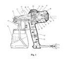
- FIG. 1 is a sectional structure view of the invention.
- FIG. 2 is a sectional structure view of the invention with the wind-collecting cover invisible.
- the invention provides a handheld electric spray gun, comprising a gun body 20 , a spray can 10 , a base 40 for connecting the gun body 20 with the spray can 10 and a housing 60 .
- the gun body 20 , the base 40 , the spray can 10 and the housing 60 constitute the basic structure of the invention.
- a nozzle 21 is provided at the front end of the gun body 20 .
- the nozzle 21 is connected with the inner chamber of the spray can 10 through pipelines.
- the housing 60 is formed by a left housing and a right housing fixedly connected with each other.
- the upper portion of the housing 60 is formed with a chamber 61 , and the lower portion thereof is formed with a handle 62 .
- the chamber 61 is communicated with the gun body 20 .
- the chamber 61 is provided with a motor 30 therein.
- the motor 30 comprises a motor shaft 36 , a rotor 33 and blades 32 all sleeved on the motor shaft 36 , a stator 34 provided correspondingly to the rotor 33 , an air-outtake ring 31 and a carbon brush bracket 37 .
- the rotor 33 is provided on the air-intake side of the blades 32 .
- Two ends of the motor shaft 36 are fixed with a bearing 38 , respectively.
- Both the air-outtake ring 31 and the carbon brush bracket 37 are provided with a bearing seat, respectively.
- the bearing 38 disposed on the air-outtake side of the blades 32 is fixed in the bearing seat of the air-outtake ring 31 while the bearing 38 disposed at the outer end of the rotor 33 is fixed in the bearing seat of the carbon brush bracket 37 .
- the air-outtake ring 31 is disposed at a position where the chamber 61 is connected with the gun body 20 .
- the blades 32 are sleeved on the motor shaft 36 .
- the rotor 33 is disposed on the air-intake side of the blades 32 .
- the stator 34 and the rotor 33 are disposed correspondingly, that is, a stator and rotor assembly (the stator 34 and the rotor 33 ) is disposed on the air-intake side of the blades 32 .
- a stator and rotor assembly is generally disposed on the air-outtake side of the blades.
- the motor 30 of the invention has better heat dissipation effect.
- the blades 32 can well pump heat generated during the working of the stator and rotor assembly (the stator 34 and the rotor 33 ) by cold air entering the electric spray gun, superior to heat dissipation by blowing by conventional motors.
- the motor 30 of the invention further comprises a wind-collecting cover 35 , two ends of which are provided with a first accommodating chamber 351 and a second accommodating chamber 352 , respectively, the first accommodating chamber 351 being communicated with the second accommodating chamber 352 , with the blades 32 disposed in the second accommodating chamber 352 and the stator 34 disposed in the first accommodating chamber 351 .
- the wind-collecting cover 35 of the invention has the function of collecting wind power, not only enhancing the air-intake and pumping effects of the blades 32 , but also improving the air-outtake effect of the blades 32 . When the power of the motor 30 is kept unchanged, the invention has better heat dissipation effect and air-outtake effect.
- the air-outtake ring 31 is provided with a plurality of spiral air flues thereon, mainly for adjusting the direction of wind so that the nozzle 21 achieves better air spraying effect.
- the axis of the motor and the central axis of the chamber 61 are disposed in a negative angle A which is 0°-30°, preferably, 0°-5°. With such arrangement, the structure of the invention is more compact, and it is more convenient for handholding the handle 62 .
- the gun body 20 is provided with a hook 50 thereon, for hooking the electrical spray gun conveniently, thereby effectively saving the storage space.
- the handheld electric spray gun of the invention adopts a novel structure of the motor 30 where a stator and rotor assembly (the stator 34 and the rotor 33 ) is disposed on the air-intake side of the blades 32 , that is, the stator and rotor assembly is disposed at the air inlet, in this way, the stator and rotor assembly may be forcibly cooled with cold air, thus the heat dissipation effect is greatly improved.
- the power of the motor is kept unchanged, the atomization effect is greatly enhanced, and the service life is greatly prolonged.
Landscapes
- Engineering & Computer Science (AREA)
- Power Engineering (AREA)
- Nozzles (AREA)
- Connection Of Motors, Electrical Generators, Mechanical Devices, And The Like (AREA)
Abstract
Description
Claims (7)
Applications Claiming Priority (4)
| Application Number | Priority Date | Filing Date | Title |
|---|---|---|---|
| CN201110005569.3 | 2011-01-12 | ||
| CN201110005569.3A CN102101084B (en) | 2011-01-12 | 2011-01-12 | Handheld electric spray gun |
| CN201110005569 | 2011-01-12 | ||
| PCT/CN2011/071594 WO2012094846A1 (en) | 2011-01-12 | 2011-03-07 | Handheld electric spray gun |
Publications (2)
| Publication Number | Publication Date |
|---|---|
| US20130277458A1 US20130277458A1 (en) | 2013-10-24 |
| US8944348B2 true US8944348B2 (en) | 2015-02-03 |
Family
ID=44154260
Family Applications (1)
| Application Number | Title | Priority Date | Filing Date |
|---|---|---|---|
| US13/978,559 Expired - Fee Related US8944348B2 (en) | 2011-01-12 | 2011-03-07 | Handheld electric spray gun |
Country Status (4)
| Country | Link |
|---|---|
| US (1) | US8944348B2 (en) |
| EP (1) | EP2664387A4 (en) |
| CN (1) | CN102101084B (en) |
| WO (1) | WO2012094846A1 (en) |
Cited By (8)
| Publication number | Priority date | Publication date | Assignee | Title |
|---|---|---|---|---|
| USD796004S1 (en) * | 2016-04-18 | 2017-08-29 | Zhejiang Prulde Electric Appliance Co., Ltd. | Spray gun |
| USD796630S1 (en) * | 2016-04-18 | 2017-09-05 | Zhejiang Prulde Electric Appliance Co., Ltd. | Spray gun |
| US20210402426A1 (en) * | 2019-09-12 | 2021-12-30 | Kudachi Business Consultants, LLC | Dispensing paintbrush |
| USD947992S1 (en) * | 2019-12-26 | 2022-04-05 | Zhejiang Prulde Electric Appliance Co., Ltd. | Spray gun |
| US20220274123A1 (en) * | 2019-11-19 | 2022-09-01 | Positec Power Tools (Suzhou) Co., Ltd. | Spray gun |
| US20220355321A1 (en) * | 2021-05-05 | 2022-11-10 | Uniweld Products, Inc. | Retaining Bracket For Applicator Rod, Fluid Spray Application System Including The Same, And Method Of Applying A Fluid To A Target Object |
| US11986850B2 (en) | 2018-04-10 | 2024-05-21 | Graco Minnesota Inc. | Handheld airless sprayer for paints and other coatings |
| USD1044177S1 (en) | 2022-04-14 | 2024-09-24 | Jmsn, Llc | Shoe cleaning device |
Families Citing this family (16)
| Publication number | Priority date | Publication date | Assignee | Title |
|---|---|---|---|---|
| CN201956807U (en) * | 2011-01-12 | 2011-08-31 | 奉化市威优特电器有限公司 | Motor special for spray gun |
| CN102773179A (en) * | 2012-07-11 | 2012-11-14 | 奉化市威优特电器有限公司 | Rechargeable direct current type electric spray gun |
| CN203664079U (en) * | 2014-01-08 | 2014-06-25 | 台州市洛克赛工具有限公司 | Multifunctional electric spray gun |
| WO2015176123A1 (en) * | 2014-05-19 | 2015-11-26 | Tanning Tech Pty Ltd | Apparatus and methods for spraying a cosmetic composition |
| DE102014116148A1 (en) * | 2014-11-06 | 2016-05-12 | G-Mate Ag | Spray gun for atomising liquids |
| CN108889511B (en) * | 2018-08-03 | 2021-04-06 | 深圳市福来过科技有限公司 | Paint spraying equipment based on exhaust-gas treatment for wood working |
| EP3890891B1 (en) * | 2018-12-04 | 2024-08-07 | Bellassa GmbH | Paint spray gun |
| CN113385324B (en) * | 2020-03-12 | 2025-08-19 | 苏州宝时得电动工具有限公司 | spray gun |
| CN111701741A (en) * | 2020-07-27 | 2020-09-25 | 宁波家瑞工具制造有限公司 | Centrifugal fan spray gun |
| CN112090618B (en) | 2020-08-27 | 2021-08-24 | 浙江普莱得电器股份有限公司 | an atomizer |
| USD1041279S1 (en) | 2021-09-02 | 2024-09-10 | Techtronic Cordless Gp | Pruner saw |
| CN115842435A (en) * | 2021-09-22 | 2023-03-24 | 创科无线普通合伙 | Hand-held electric tool and motor assembly for electric tool |
| CN113976345B (en) * | 2021-10-29 | 2023-03-21 | 宁波家瑞工具制造有限公司 | Centrifugal fan blade spray gun |
| USD1030955S1 (en) * | 2022-04-02 | 2024-06-11 | Zhejiang Prulde Electric Appliance Co., Ltd. | Electric spray gun |
| CN116944586A (en) | 2022-04-12 | 2023-10-27 | 创科无线普通合伙 | Hand-held electric tool |
| USD1060607S1 (en) * | 2022-08-25 | 2025-02-04 | Sistem Teknik Makina Sanayi Ve Ticaret Anonim Sirketi | Paint spray gun |
Citations (10)
| Publication number | Priority date | Publication date | Assignee | Title |
|---|---|---|---|---|
| US4221331A (en) * | 1979-02-26 | 1980-09-09 | Goran Jr Leo | Atomizing apparatus |
| US4301971A (en) * | 1979-08-23 | 1981-11-24 | Cornelius Engineering Center, Inc. | Electrically-driven spray gun |
| US4693423A (en) * | 1986-02-25 | 1987-09-15 | The Wooster Brush Company | Power paint sprayer |
| US20070252019A1 (en) * | 2006-04-26 | 2007-11-01 | Wagner Spray Tech Corporation | Texture sprayer |
| US7303149B1 (en) * | 2007-03-20 | 2007-12-04 | Huang Jung-Kun | Automatic spray gun |
| US7360720B2 (en) * | 2004-06-04 | 2008-04-22 | J. Wagner Gmbh | Spray gun |
| US7478766B2 (en) * | 2004-06-29 | 2009-01-20 | Clarke Consumer Products, Inc. | Portable sprayer with connector mounting beams |
| US7891588B2 (en) * | 2006-05-31 | 2011-02-22 | Wagner Spray Tech Corporation | Quick disconnect for wetted parts in a paint spray gun |
| US8573511B2 (en) * | 2009-03-20 | 2013-11-05 | Wagner Spray Tech Corporation | Dual voltage electromagnet motor for airless fluid sprayer |
| US8596555B2 (en) * | 2008-10-22 | 2013-12-03 | Graco Minnesota Inc. | Portable airless sprayer |
Family Cites Families (7)
| Publication number | Priority date | Publication date | Assignee | Title |
|---|---|---|---|---|
| DE3931814A1 (en) * | 1989-09-23 | 1991-04-04 | Black & Decker Inc | MANUAL HIGH PRESSURE CLEANER |
| CN2221448Y (en) * | 1994-04-18 | 1996-03-06 | 伍建国 | Portable multi-functional automatic spray gun |
| JP2852636B2 (en) * | 1995-09-19 | 1999-02-03 | 富士ロビン株式会社 | Chemical sprayer for control |
| US7083119B2 (en) * | 2003-09-25 | 2006-08-01 | 3M Innovative Properties Company | Security clip for spray gun connector |
| CN2684939Y (en) * | 2004-02-10 | 2005-03-16 | 陈立新 | Air-aspiration type sprayer |
| CN201684688U (en) * | 2010-02-10 | 2010-12-29 | 浙江普莱得电器有限公司 | Electric spray gun |
| CN201949965U (en) * | 2011-01-12 | 2011-08-31 | 奉化市威优特电器有限公司 | Hand-held electric spray gun |
-
2011
- 2011-01-12 CN CN201110005569.3A patent/CN102101084B/en not_active Ceased
- 2011-03-07 WO PCT/CN2011/071594 patent/WO2012094846A1/en not_active Ceased
- 2011-03-07 EP EP11855482.3A patent/EP2664387A4/en not_active Withdrawn
- 2011-03-07 US US13/978,559 patent/US8944348B2/en not_active Expired - Fee Related
Patent Citations (10)
| Publication number | Priority date | Publication date | Assignee | Title |
|---|---|---|---|---|
| US4221331A (en) * | 1979-02-26 | 1980-09-09 | Goran Jr Leo | Atomizing apparatus |
| US4301971A (en) * | 1979-08-23 | 1981-11-24 | Cornelius Engineering Center, Inc. | Electrically-driven spray gun |
| US4693423A (en) * | 1986-02-25 | 1987-09-15 | The Wooster Brush Company | Power paint sprayer |
| US7360720B2 (en) * | 2004-06-04 | 2008-04-22 | J. Wagner Gmbh | Spray gun |
| US7478766B2 (en) * | 2004-06-29 | 2009-01-20 | Clarke Consumer Products, Inc. | Portable sprayer with connector mounting beams |
| US20070252019A1 (en) * | 2006-04-26 | 2007-11-01 | Wagner Spray Tech Corporation | Texture sprayer |
| US7891588B2 (en) * | 2006-05-31 | 2011-02-22 | Wagner Spray Tech Corporation | Quick disconnect for wetted parts in a paint spray gun |
| US7303149B1 (en) * | 2007-03-20 | 2007-12-04 | Huang Jung-Kun | Automatic spray gun |
| US8596555B2 (en) * | 2008-10-22 | 2013-12-03 | Graco Minnesota Inc. | Portable airless sprayer |
| US8573511B2 (en) * | 2009-03-20 | 2013-11-05 | Wagner Spray Tech Corporation | Dual voltage electromagnet motor for airless fluid sprayer |
Cited By (11)
| Publication number | Priority date | Publication date | Assignee | Title |
|---|---|---|---|---|
| USD796004S1 (en) * | 2016-04-18 | 2017-08-29 | Zhejiang Prulde Electric Appliance Co., Ltd. | Spray gun |
| USD796630S1 (en) * | 2016-04-18 | 2017-09-05 | Zhejiang Prulde Electric Appliance Co., Ltd. | Spray gun |
| US11986850B2 (en) | 2018-04-10 | 2024-05-21 | Graco Minnesota Inc. | Handheld airless sprayer for paints and other coatings |
| US20210402426A1 (en) * | 2019-09-12 | 2021-12-30 | Kudachi Business Consultants, LLC | Dispensing paintbrush |
| US11745214B2 (en) * | 2019-09-12 | 2023-09-05 | Kudachi Business Consultants, LLC | Dispensing paintbrush |
| US20220274123A1 (en) * | 2019-11-19 | 2022-09-01 | Positec Power Tools (Suzhou) Co., Ltd. | Spray gun |
| US12303927B2 (en) * | 2019-11-19 | 2025-05-20 | Positec Power Tools (Suzhou) Co., Ltd. | Spray gun |
| USD947992S1 (en) * | 2019-12-26 | 2022-04-05 | Zhejiang Prulde Electric Appliance Co., Ltd. | Spray gun |
| US20220355321A1 (en) * | 2021-05-05 | 2022-11-10 | Uniweld Products, Inc. | Retaining Bracket For Applicator Rod, Fluid Spray Application System Including The Same, And Method Of Applying A Fluid To A Target Object |
| US11548020B2 (en) * | 2021-05-05 | 2023-01-10 | Uniweld Products, Inc. | Retaining bracket for applicator rod, fluid spray application system including the same, and method of applying a fluid to a target object |
| USD1044177S1 (en) | 2022-04-14 | 2024-09-24 | Jmsn, Llc | Shoe cleaning device |
Also Published As
| Publication number | Publication date |
|---|---|
| WO2012094846A1 (en) | 2012-07-19 |
| EP2664387A1 (en) | 2013-11-20 |
| CN102101084B (en) | 2013-03-20 |
| US20130277458A1 (en) | 2013-10-24 |
| CN102101084A (en) | 2011-06-22 |
| EP2664387A4 (en) | 2014-12-03 |
Similar Documents
| Publication | Publication Date | Title |
|---|---|---|
| US8944348B2 (en) | Handheld electric spray gun | |
| CN103752442B (en) | rechargeable handheld electric spray gun | |
| CN114215775B (en) | Portable bladeless fan | |
| US9091452B2 (en) | Misting fan | |
| US8205806B2 (en) | Misting fan | |
| US20050269425A1 (en) | Spray gun | |
| CN112892899B (en) | Spray gun | |
| CN202056121U (en) | No-blade fan device with atomizing function | |
| US20140008461A1 (en) | Fan with atomization nozzles | |
| US20080099934A1 (en) | Nebulization Fan | |
| CN201949965U (en) | Hand-held electric spray gun | |
| CN113441308A (en) | Atomization device | |
| CN203750739U (en) | Handheld electric spray gun | |
| CN106642463B (en) | A kind of structure improved Spray fan | |
| EP1906106A1 (en) | Nebulization fan | |
| CN212883204U (en) | An electronic atomization device | |
| CN210371241U (en) | Portable fan | |
| CN213792303U (en) | Hand-held electric spray gun | |
| CN207353954U (en) | Water atomization motor | |
| CN209362766U (en) | A kind of new energy commercial vehicle motor case processing integrated molding equipment | |
| CN211587148U (en) | Electrostatic enamel powder spraying equipment for producing gas barbecue oven | |
| CN109723658B (en) | Evaporation fan | |
| CN223009797U (en) | Handheld thin cigarette system | |
| CN202955000U (en) | Fan | |
| CN211726225U (en) | Direct-injection silencing gun head applied to plasma cleaning machine |
Legal Events
| Date | Code | Title | Description |
|---|---|---|---|
| AS | Assignment |
Owner name: FENGHUA WEILDER ELECTRIC APPLIANCE CO., LTD., CHIN Free format text: ASSIGNMENT OF ASSIGNORS INTEREST;ASSIGNORS:ZHOU, HAOWEI;HUANG, LIJUN;REEL/FRAME:030763/0654 Effective date: 20130629 |
|
| FEPP | Fee payment procedure |
Free format text: MAINTENANCE FEE REMINDER MAILED (ORIGINAL EVENT CODE: REM.); ENTITY STATUS OF PATENT OWNER: SMALL ENTITY |
|
| LAPS | Lapse for failure to pay maintenance fees |
Free format text: PATENT EXPIRED FOR FAILURE TO PAY MAINTENANCE FEES (ORIGINAL EVENT CODE: EXP.); ENTITY STATUS OF PATENT OWNER: SMALL ENTITY |
|
| STCH | Information on status: patent discontinuation |
Free format text: PATENT EXPIRED DUE TO NONPAYMENT OF MAINTENANCE FEES UNDER 37 CFR 1.362 |
|
| FP | Lapsed due to failure to pay maintenance fee |
Effective date: 20190203 |