US8944258B2 - Bicycle parking apparatus - Google Patents
Bicycle parking apparatus Download PDFInfo
- Publication number
- US8944258B2 US8944258B2 US13/694,718 US201213694718A US8944258B2 US 8944258 B2 US8944258 B2 US 8944258B2 US 201213694718 A US201213694718 A US 201213694718A US 8944258 B2 US8944258 B2 US 8944258B2
- Authority
- US
- United States
- Prior art keywords
- tubular shaft
- tubular
- shafts
- shaft
- parking base
- Prior art date
- Legal status (The legal status is an assumption and is not a legal conclusion. Google has not performed a legal analysis and makes no representation as to the accuracy of the status listed.)
- Expired - Fee Related
Links
Images


Classifications
-
- B—PERFORMING OPERATIONS; TRANSPORTING
- B62—LAND VEHICLES FOR TRAVELLING OTHERWISE THAN ON RAILS
- B62H—CYCLE STANDS; SUPPORTS OR HOLDERS FOR PARKING OR STORING CYCLES; APPLIANCES PREVENTING OR INDICATING UNAUTHORIZED USE OR THEFT OF CYCLES; LOCKS INTEGRAL WITH CYCLES; DEVICES FOR LEARNING TO RIDE CYCLES
- B62H3/00—Separate supports or holders for parking or storing cycles
-
- A—HUMAN NECESSITIES
- A47—FURNITURE; DOMESTIC ARTICLES OR APPLIANCES; COFFEE MILLS; SPICE MILLS; SUCTION CLEANERS IN GENERAL
- A47B—TABLES; DESKS; OFFICE FURNITURE; CABINETS; DRAWERS; GENERAL DETAILS OF FURNITURE
- A47B45/00—Cabinets, racks or shelf units, characterised by features enabling enlarging in height, length, or depth
-
- A—HUMAN NECESSITIES
- A47—FURNITURE; DOMESTIC ARTICLES OR APPLIANCES; COFFEE MILLS; SPICE MILLS; SUCTION CLEANERS IN GENERAL
- A47F—SPECIAL FURNITURE, FITTINGS, OR ACCESSORIES FOR SHOPS, STOREHOUSES, BARS, RESTAURANTS OR THE LIKE; PAYING COUNTERS
- A47F5/00—Show stands, hangers, or shelves characterised by their constructional features
- A47F5/10—Adjustable or foldable or dismountable display stands
-
- A—HUMAN NECESSITIES
- A47—FURNITURE; DOMESTIC ARTICLES OR APPLIANCES; COFFEE MILLS; SPICE MILLS; SUCTION CLEANERS IN GENERAL
- A47F—SPECIAL FURNITURE, FITTINGS, OR ACCESSORIES FOR SHOPS, STOREHOUSES, BARS, RESTAURANTS OR THE LIKE; PAYING COUNTERS
- A47F7/00—Show stands, hangers, or shelves, adapted for particular articles or materials
- A47F7/04—Show stands, hangers, or shelves, adapted for particular articles or materials for tyres; for wheels
-
- B—PERFORMING OPERATIONS; TRANSPORTING
- B60—VEHICLES IN GENERAL
- B60R—VEHICLES, VEHICLE FITTINGS, OR VEHICLE PARTS, NOT OTHERWISE PROVIDED FOR
- B60R9/00—Supplementary fittings on vehicle exterior for carrying loads, e.g. luggage, sports gear or the like
- B60R9/08—Supplementary fittings on vehicle exterior for carrying loads, e.g. luggage, sports gear or the like specially adapted for sports gear
- B60R9/10—Supplementary fittings on vehicle exterior for carrying loads, e.g. luggage, sports gear or the like specially adapted for sports gear for cycles
-
- B—PERFORMING OPERATIONS; TRANSPORTING
- B62—LAND VEHICLES FOR TRAVELLING OTHERWISE THAN ON RAILS
- B62H—CYCLE STANDS; SUPPORTS OR HOLDERS FOR PARKING OR STORING CYCLES; APPLIANCES PREVENTING OR INDICATING UNAUTHORIZED USE OR THEFT OF CYCLES; LOCKS INTEGRAL WITH CYCLES; DEVICES FOR LEARNING TO RIDE CYCLES
- B62H3/00—Separate supports or holders for parking or storing cycles
- B62H3/04—Separate supports or holders for parking or storing cycles involving forked supports of brackets for holding a wheel
- B62H3/06—Separate supports or holders for parking or storing cycles involving forked supports of brackets for holding a wheel collapsible
Definitions
- the present invention relates to an improved bicycle parking apparatus, more particularly to an improvement for a bicycle parking apparatus adapted for adjusting the size of the apparatus to minimize its storage volume.
- Taiwanese Patent TW1002244119 it is known, for example as described in Taiwanese Patent TW1002244119 to provide a collapsible automobile frame structure, wherein an automobile frame structure is disclosed, comprising: a lower frame having a lower tank; a first tubular shaft that is adjustably attached onto a lower frame, the first tubular shaft has two sets of multiple-gear second tubular shafts located on an upper end of the first tubular shaft at an end of the first tubular shaft as connected by a connecting tubular shaft, so as to form a lateral frame tank between the two sets of multiple-gear second tubular shafts.
- a known disadvantage with this prior invention is the complicated and redundant work processing involved.
- an object of the present invention is mainly focused on improving over this issue.
- a utility patent application is further requested herewith at the completion of the present invention.
- a primary object of the present invention is to provide an improved bicycle parking apparatus having a second tubular shaft, which, by the adjustment of the tubular shaft, can work to effectively reduce its volume, to minimize its storage volume.
- the present invention discloses an improvement for a bicycle parking apparatus, the apparatus comprises: a parking base having a first tubular shaft, a pair of second tubular shaft, a pair of third tubular shaft and a pair of tubular shaft jacket; wherein, the parking base is made of an assembly of the first tubular shaft and the second tubular shaft that are arrayed in a parallel fashion.
- a pair of parallel third tubular shafts is securely disposed between the first tubular shaft and the second tubular shaft in an interweaving fashion, a side of the third tubular shaft curves and extends in an upward direction and the diameter at the distal end tapers to form a second connector, the outer diameter of the second connector is smaller than the outer diameter of the enfolding portion so as to permit a fitting installment;
- a first locking member is disposed on the third tubular shaft at a position in contact with the second connector, the first locking member is composed of a pin and a flexible plate; an end of the pin operably extends through the outer perimeter of the second connector, and the other end of the pin is connected to an end of the parabolic-shaped flexible plate, the flexible plate can operably work to support an end of the pin to be held protruding outwardly from the outer perimeter of the second connector;
- the third tubular shaft has a tubular space for allowing extension and contraction of the second tubular shaft when the second tubular shaft is inserted therein.
- a tubular shaft jacket can be attached to a tubular shaft opening underneath the first tubular shaft, an outer diameter of an end of the tubular shaft jacket is slightly larger than the outer diameter of the first tubular shaft, the outer diameter of the connector at the other end occurs to appropriately fit the inner diameter of the tubular shaft.
- the connector is attached onto the inner wall of the tubular shaft in such a way that the expanded portion of the second tubular shaft is securely positioned at the connector after the second tubular shaft is inserted into the tubular shaft opening.
- the second tubular shaft After the second tubular shaft expands to its longest form, due to the configuration of the diameter of the expanded portion located at an end of the second tubular shaft being larger than the diameter of the enfolding portion, the second tubular shaft can occur to be fastened in a fixed position and not disconnect from the first tubular shaft;
- the second tubular shaft is a metallic tubular shaft, wherein a bottom end of the shaft is disposed with an enfolding portion, which is configured to work to connect the second connector of the third tubular shaft, wherein the other end of the relative base end has an expanded portion so as to allow the first tubular shaft to be fastened to a given position.
- a pin locking member is located at a side of the enfolding portion at the based end of the second tubular shaft, the purpose of which is to immobilize the pin of the third tubular shaft;
- the tubular shaft jacket is a plastic work piece, the outer diameter of an end of it is larger than the outer diameter of the first tubular shaft, and the other end is disposed with a connector, whose outer diameter occurs to fit the inner diameter of the tubular shaft opening.
- the third tubular shaft has a second connector and a pin, which are involved in the assembly with the enfolding portion of the second tubular shaft; for the parking base, two parallel frames are welded or threaded to the third tubular shaft, when the parking base and the third tubular shaft are combined into a single device, the second tubular shaft works to insert into the second connector of the third tubular shaft. Due to the effect of an elastic device, the pin installed on the second connector can be attached in the pin locking member of the second tubular shaft, the second tubular shaft is retractable within the tubular shaft of the first tubular shaft, so that the length of the second tubular shaft can be effectively shortened to a manageable size for storage.
- FIG. 1 is an exploded perspective view of an apparatus of the present invention.
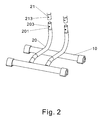
- FIG. 2 is a schematic diagram showing a portion of the apparatus of the present invention.
- FIG. 3-1 is a cross-sectional view showing a portion of the apparatus of the present invention.
- FIG. 3-2 is another cross-sectional view showing a portion of the apparatus of the present invention.
- FIG. 4 is an example showing preferred embodiment of the present invention in its full extended form.
- FIG. 5 is an example showing preferred embodiment of the present invention in its collapsible form.
- an improved bicycle parking apparatus of the present invention comprising: a parking base 10 , a pair of third tubular shaft 20 , a pair of second tubular shaft 21 , and a pair of tubular shaft jacket 23 ; wherein, the parking base 10 is made of a first frame 101 and a second frame 102 assembled in a parallel arrangement, a pair of parallel third tubular shafts 20 is disposed in a perpendicular fashion between the first frame 101 and the second frame 102 by means of lock or welding, the third tubular shaft 20 has a first connector 201 and a second connector 202 , the first connector 201 is welded onto the first frame 101 , a side of the third tubular shaft 20 curves and extends upward, and is welded onto the second frame 102 at a position where the third tubular shaft curves.
- the third tubular shaft tapers off in size when inside the second connector 202 , the outer diameter of the tubular shaft of the second connector 202 is smaller than the outer diameter of the enfold
- a first pin locking member is disposed on the third tubular shaft 20 at the second connector 202 , the first pin locking member comprises a pin 203 and a flexible plate; an end of the described pin 203 sticks out through the outer perimeter of the second connector 202 , the other end of which is connected to an end of the parabolic shaped flexible plate, an end of the pin 203 can be held out to stick outside the outer perimeter by the support of the flexible plate;
- the second tubular shaft 21 is a metallic tubular shaft, wherein the parking base has an enfolding portion 211 , which can work to connect with the second connector 202 of the third tubular shaft 20 , the relatively other end of the parking base is disposed with an expanded portion 212 , so as to allow the first tubular shaft 22 to be fixed to a specific position. Additionally, a pin locking member 213 is disposed at a side of the enfolding portion 211 of the bottom end of the second tubular shaft 21 , which can work to restrict the pin 203 of the third tubular shaft 20 to a specific position;
- the tubular shaft jacket 23 is a plastic work piece, an outer diameter of an end is larger than an outer diameter of the first tubular shaft 22 , the other end has a coupling portion 231 , the outer diameter of which occurs to fit the inner diameter of the tubular shaft opening 221 .
- a preferred embodiment of the present invention is characterized in that: the first tubular shaft 22 has a tubular shaft space that allows extension and contraction of the second tubular shaft 21 , the tubular shaft opening 221 beneath the first tubular shaft 22 can be attached by gluing with a tubular shaft jacket 23 ;
- the manners by which the second tubular shaft 21 and the first tubular shaft 22 are produced and assembled are: after the first tubular shaft jacket 23 is installed in the second tubular shaft 21 , a mechanical means operates to expand its distal end into an expanded portion 212 , so as to insert the second tubular shaft 21 into the first tubular shaft 22 , and further make the connector 231 of the tubular shaft jacket 23 attached to the tubular shaft opening of the first tubular shaft 22 , for the purpose of inserting the second tubular shaft 21 into the tubular shaft 221 of the first tubular shaft 22 , when the second tubular shaft 21 is expanded, the expanded portion 212 would be securely fixed into a specific position at the connector 231 ; after the second tubular shaft 21 is expanded to its highest length, because the expanded portion 212 at the distal end of the second tubular shaft is larger than the connector 231 of the tubular shat jacket 23 , the second tubular shaft 21 occurs to be securely fixed into a specific position and not disconnect from the tubular shaft of the first tubular shaft
- the second tubular shaft 21 when the second tubular shaft 21 is in its collapsible form within the first tubular shaft 22 , only a minimal force is required to press downward on the first tubular shaft 22 , to disengage the expanded portion 212 of the second tubular shaft 21 from the connector 231 of the tubular shaft jacket 23 and move toward the first tubular shaft 22 , as shown in FIG. 3-1 , wherein the tubular shaft jacket 23 is made of plastic. Due to the combined effect of flexible property of the plastic and the rigid property of the metal material of the second tubular shaft 21 , the second tubular shaft 21 can be temporarily fixed into the distal end of the connector 231 of the tubular shaft jacket 23 , as shown in FIG. 3-2 ; under the applied pressure of the first tubular shaft 22 , the second tubular shaft 21 will be disengaged from the connector 231 of the tubular shaft jacket 23 and collapse toward the first tubular shaft 22 , by which to minimize the volume of the entire parking structure.
- the second tubular shaft 21 of the present invention When the second tubular shaft 21 of the present invention is assembled with the first tubular shaft 22 , the second tubular shaft 21 is inserted from bottom to top, into the inner tubular space of the first tubular shaft 22 through its tubular shaft opening 221 Afterwards, the connector 231 of the tubular shaft jacket 23 is inserted into the tubular shaft opening 221 before subject to attachment by gluing or threading.
- the expanded portion at the upper end of the second tubular shaft 21 can be pulled to reach the connector 231 before immediately becoming securely fixed in a specific position, the secure fixing operates by using the weight of the first tubular shaft 22 , when the first tubular shaft 22 is pulled upward, the first tubular shaft 22 will be subject to inclination due to its weight, through this mechanism, the expanded portion 212 can be securely fixed inside the tubular shaft of the first tubular shaft 22 , with the plastic property of the tubular shaft jacket 23 , the fixing of the expanded portion 212 on the edge of the distal end of the connector 231 can be further strengthened.
- the second tubular shaft 21 is made from metallic material, the tubular shaft jacket 23 is made from plastic material, and the second tubular shaft 21 can also be a tubular shaft connected by a multi-gear mechanism.
Landscapes
- Engineering & Computer Science (AREA)
- Mechanical Engineering (AREA)
- Mutual Connection Of Rods And Tubes (AREA)
Abstract
Description
Claims (9)
Priority Applications (1)
| Application Number | Priority Date | Filing Date | Title |
|---|---|---|---|
| US13/694,718 US8944258B2 (en) | 2012-12-27 | 2012-12-27 | Bicycle parking apparatus |
Applications Claiming Priority (1)
| Application Number | Priority Date | Filing Date | Title |
|---|---|---|---|
| US13/694,718 US8944258B2 (en) | 2012-12-27 | 2012-12-27 | Bicycle parking apparatus |
Publications (2)
| Publication Number | Publication Date |
|---|---|
| US20140183147A1 US20140183147A1 (en) | 2014-07-03 |
| US8944258B2 true US8944258B2 (en) | 2015-02-03 |
Family
ID=51015958
Family Applications (1)
| Application Number | Title | Priority Date | Filing Date |
|---|---|---|---|
| US13/694,718 Expired - Fee Related US8944258B2 (en) | 2012-12-27 | 2012-12-27 | Bicycle parking apparatus |
Country Status (1)
| Country | Link |
|---|---|
| US (1) | US8944258B2 (en) |
Cited By (2)
| Publication number | Priority date | Publication date | Assignee | Title |
|---|---|---|---|---|
| USD745064S1 (en) * | 2014-02-06 | 2015-12-08 | Rhino Tool Company | Post driver handle |
| US11839966B1 (en) | 2020-06-09 | 2023-12-12 | Rakstand, Llc | Bicycle stand and repair apparatus |
Families Citing this family (6)
| Publication number | Priority date | Publication date | Assignee | Title |
|---|---|---|---|---|
| CN105947029B (en) * | 2016-06-21 | 2018-05-08 | 陕西科技大学 | A kind of self-service car locking that public arena uses, parking apparatus |
| GB201910420D0 (en) * | 2019-07-19 | 2019-09-04 | Demers Guy | dismountable support stand for two-wheeled vechicle |
| USD908048S1 (en) * | 2019-09-10 | 2021-01-19 | Officine Parolin S.R.L. | Bicycle parking rack |
| US10850784B1 (en) * | 2019-12-27 | 2020-12-01 | David A. Hamilton | Multi-adjustment bicycle rack for storage area |
| CA3119356A1 (en) * | 2021-05-21 | 2022-11-21 | Canadian Tire Corporation, Limited | Wheel storage apparatus and kit |
| USD1020545S1 (en) * | 2022-09-07 | 2024-04-02 | Chenlei Zhao | Bicycle parking rack |
Citations (46)
| Publication number | Priority date | Publication date | Assignee | Title |
|---|---|---|---|---|
| US528028A (en) * | 1894-10-23 | Bicycle-stand | ||
| US547412A (en) * | 1895-10-08 | Bicycle-stand | ||
| US556758A (en) * | 1896-03-24 | Bicycle-support | ||
| US574628A (en) * | 1897-01-05 | Harry c | ||
| US602665A (en) * | 1898-04-19 | Bicycle-stand | ||
| US603422A (en) * | 1898-05-03 | Bicycle-stand | ||
| US640631A (en) * | 1899-06-02 | 1900-01-02 | Ambrogio Enrico Conti | Bicycle-support. |
| US1202444A (en) * | 1916-06-03 | 1916-10-24 | Charles J Soleau | Combined bicycle rack and lock. |
| US1241486A (en) * | 1915-09-23 | 1917-10-02 | Mckinnon Dash Company | Folding stand or support. |
| US2707841A (en) * | 1951-10-15 | 1955-05-10 | Florence H Figura | Laundry appliances |
| US3202289A (en) * | 1963-07-01 | 1965-08-24 | Frederic M Burditt | Stand for bicycles and the like |
| US3348697A (en) * | 1966-04-01 | 1967-10-24 | Persons Majestic Mfg Company | Unicycle stand construction |
| US3722702A (en) * | 1971-03-22 | 1973-03-27 | Garcy Corp | Foldable garment rack |
| US4609183A (en) * | 1984-09-07 | 1986-09-02 | Whittar Industries, Ltd. | Shopping cart corral kit and method of assembling a corral from the component parts of the kit |
| US4768782A (en) * | 1987-02-09 | 1988-09-06 | Blackburn Designs, Inc. | Bicycle exercising apparatus |
| US4941651A (en) * | 1988-05-13 | 1990-07-17 | Rts Trainer Corporation | Bicycle trainer |
| US4979759A (en) * | 1989-06-23 | 1990-12-25 | Michael Solovay | Free-standing bike stand |
| US5050785A (en) * | 1990-05-31 | 1991-09-24 | Gayle Hays | Bicycle rack for fifth-wheel trailer |
| US5082120A (en) * | 1988-05-13 | 1992-01-21 | Vega James S | Free standing bike rack |
| US5088420A (en) * | 1986-10-23 | 1992-02-18 | Russell Edwin R | Work station |
| US5090725A (en) * | 1990-08-06 | 1992-02-25 | Feldner Robert H | Collapsible garment cart |
| US5108141A (en) * | 1989-11-13 | 1992-04-28 | Anderson Leona F | Demountable rack for trucks with canopies |
| US5417629A (en) * | 1991-10-31 | 1995-05-23 | Phipps; Gary G. B. | Axle mounting bicycle stand and carrier |
| US5660637A (en) * | 1995-11-13 | 1997-08-26 | Dodge; John P. | Paint rack for a vehicle body shop |
| US5862921A (en) * | 1997-05-02 | 1999-01-26 | Venegas Jr.; Frank | Cart corral |
| US6053337A (en) * | 1998-02-23 | 2000-04-25 | Venegas, Jr.; Frank | Bike rack |
| US6216882B1 (en) * | 1998-08-24 | 2001-04-17 | Jane Strunck | Retractable bicycle rack |
| US6375202B2 (en) * | 1998-02-23 | 2002-04-23 | David Weck | Household cart and method of using same |
| US20020117459A1 (en) * | 2001-02-23 | 2002-08-29 | Geng-He Chen | Stand for supporting a motorcycle |
| US20030010729A1 (en) * | 2001-06-25 | 2003-01-16 | Lopez De Luzuriaga Andres Ruiz De Gauna | Support for parking bicycles |
| US6640979B1 (en) * | 2001-04-05 | 2003-11-04 | William Rodgers Mayfield | Motorcycle parking stand |
| US6843380B1 (en) * | 1999-12-14 | 2005-01-18 | Glenn A. Fickett | Portable modular storage support device |
| US6902074B2 (en) * | 2002-06-11 | 2005-06-07 | Caitec Corporation | Support stand |
| US6983853B1 (en) * | 1999-12-14 | 2006-01-10 | Fickett Glenn A | Portable modular storage support device |
| US7108140B2 (en) * | 2002-11-27 | 2006-09-19 | Whitnall Frederick William Jam | Article support rack for vehicle |
| US20060266717A1 (en) * | 2005-05-24 | 2006-11-30 | David Tsai | Rack for bicycles |
| US20070034657A1 (en) * | 2005-08-10 | 2007-02-15 | Thule Sweden Ab | Collapsible rear mounted load carrier for a vehicle |
| USD539806S1 (en) * | 2005-06-17 | 2007-04-03 | Hon Hai Precision Industry Co. Ltd | Stand for a computer enclosure |
| US20080000848A1 (en) * | 2006-07-02 | 2008-01-03 | Ming-Sung Chiu | Bicycle Rack |
| US20080110841A1 (en) * | 2006-11-15 | 2008-05-15 | Chin-Sung Huang | Multi-function vehicle-carrying frame |
| US7658388B1 (en) * | 2008-09-16 | 2010-02-09 | Ramona Rodriguez | Cart apparatus |
| US20100237027A1 (en) * | 2009-03-20 | 2010-09-23 | Illinois Tool Works Inc. | Bicycle Stand |
| US7988000B2 (en) * | 2006-01-26 | 2011-08-02 | Target Brands, Inc. | Display fixture accessories |
| US8141888B1 (en) * | 2009-12-31 | 2012-03-27 | Levasa Chevalier Z | Surfboard transportation device |
| US8342544B1 (en) * | 2011-03-15 | 2013-01-01 | Patrick Blewett | Utility cart |
| US8360252B1 (en) * | 2010-07-22 | 2013-01-29 | Kelly Neil Fagan | Dirt bike stand and method of use thereof |
-
2012
- 2012-12-27 US US13/694,718 patent/US8944258B2/en not_active Expired - Fee Related
Patent Citations (48)
| Publication number | Priority date | Publication date | Assignee | Title |
|---|---|---|---|---|
| US528028A (en) * | 1894-10-23 | Bicycle-stand | ||
| US547412A (en) * | 1895-10-08 | Bicycle-stand | ||
| US556758A (en) * | 1896-03-24 | Bicycle-support | ||
| US574628A (en) * | 1897-01-05 | Harry c | ||
| US602665A (en) * | 1898-04-19 | Bicycle-stand | ||
| US603422A (en) * | 1898-05-03 | Bicycle-stand | ||
| US640631A (en) * | 1899-06-02 | 1900-01-02 | Ambrogio Enrico Conti | Bicycle-support. |
| US1241486A (en) * | 1915-09-23 | 1917-10-02 | Mckinnon Dash Company | Folding stand or support. |
| US1202444A (en) * | 1916-06-03 | 1916-10-24 | Charles J Soleau | Combined bicycle rack and lock. |
| US2707841A (en) * | 1951-10-15 | 1955-05-10 | Florence H Figura | Laundry appliances |
| US3202289A (en) * | 1963-07-01 | 1965-08-24 | Frederic M Burditt | Stand for bicycles and the like |
| US3348697A (en) * | 1966-04-01 | 1967-10-24 | Persons Majestic Mfg Company | Unicycle stand construction |
| US3722702A (en) * | 1971-03-22 | 1973-03-27 | Garcy Corp | Foldable garment rack |
| US4609183A (en) * | 1984-09-07 | 1986-09-02 | Whittar Industries, Ltd. | Shopping cart corral kit and method of assembling a corral from the component parts of the kit |
| US5088420A (en) * | 1986-10-23 | 1992-02-18 | Russell Edwin R | Work station |
| US4768782A (en) * | 1987-02-09 | 1988-09-06 | Blackburn Designs, Inc. | Bicycle exercising apparatus |
| US4941651A (en) * | 1988-05-13 | 1990-07-17 | Rts Trainer Corporation | Bicycle trainer |
| US5082120A (en) * | 1988-05-13 | 1992-01-21 | Vega James S | Free standing bike rack |
| US4979759A (en) * | 1989-06-23 | 1990-12-25 | Michael Solovay | Free-standing bike stand |
| US5108141A (en) * | 1989-11-13 | 1992-04-28 | Anderson Leona F | Demountable rack for trucks with canopies |
| US5050785A (en) * | 1990-05-31 | 1991-09-24 | Gayle Hays | Bicycle rack for fifth-wheel trailer |
| US5090725A (en) * | 1990-08-06 | 1992-02-25 | Feldner Robert H | Collapsible garment cart |
| US5417629A (en) * | 1991-10-31 | 1995-05-23 | Phipps; Gary G. B. | Axle mounting bicycle stand and carrier |
| US5660637A (en) * | 1995-11-13 | 1997-08-26 | Dodge; John P. | Paint rack for a vehicle body shop |
| US5862921A (en) * | 1997-05-02 | 1999-01-26 | Venegas Jr.; Frank | Cart corral |
| US6053337A (en) * | 1998-02-23 | 2000-04-25 | Venegas, Jr.; Frank | Bike rack |
| US6375202B2 (en) * | 1998-02-23 | 2002-04-23 | David Weck | Household cart and method of using same |
| US6216882B1 (en) * | 1998-08-24 | 2001-04-17 | Jane Strunck | Retractable bicycle rack |
| US6843380B1 (en) * | 1999-12-14 | 2005-01-18 | Glenn A. Fickett | Portable modular storage support device |
| US6983853B1 (en) * | 1999-12-14 | 2006-01-10 | Fickett Glenn A | Portable modular storage support device |
| US20020117459A1 (en) * | 2001-02-23 | 2002-08-29 | Geng-He Chen | Stand for supporting a motorcycle |
| US6488157B2 (en) * | 2001-02-23 | 2002-12-03 | Geng-He Chen | Stand for supporting a motorcycle |
| US6640979B1 (en) * | 2001-04-05 | 2003-11-04 | William Rodgers Mayfield | Motorcycle parking stand |
| US20030010729A1 (en) * | 2001-06-25 | 2003-01-16 | Lopez De Luzuriaga Andres Ruiz De Gauna | Support for parking bicycles |
| US6902074B2 (en) * | 2002-06-11 | 2005-06-07 | Caitec Corporation | Support stand |
| US7108140B2 (en) * | 2002-11-27 | 2006-09-19 | Whitnall Frederick William Jam | Article support rack for vehicle |
| US20060266717A1 (en) * | 2005-05-24 | 2006-11-30 | David Tsai | Rack for bicycles |
| USD539806S1 (en) * | 2005-06-17 | 2007-04-03 | Hon Hai Precision Industry Co. Ltd | Stand for a computer enclosure |
| US20070034657A1 (en) * | 2005-08-10 | 2007-02-15 | Thule Sweden Ab | Collapsible rear mounted load carrier for a vehicle |
| US7988000B2 (en) * | 2006-01-26 | 2011-08-02 | Target Brands, Inc. | Display fixture accessories |
| US20080000848A1 (en) * | 2006-07-02 | 2008-01-03 | Ming-Sung Chiu | Bicycle Rack |
| US20080110841A1 (en) * | 2006-11-15 | 2008-05-15 | Chin-Sung Huang | Multi-function vehicle-carrying frame |
| US7658388B1 (en) * | 2008-09-16 | 2010-02-09 | Ramona Rodriguez | Cart apparatus |
| US20100237027A1 (en) * | 2009-03-20 | 2010-09-23 | Illinois Tool Works Inc. | Bicycle Stand |
| US8528748B2 (en) * | 2009-03-20 | 2013-09-10 | Illinois Tool Works Inc. | Bicycle stand |
| US8141888B1 (en) * | 2009-12-31 | 2012-03-27 | Levasa Chevalier Z | Surfboard transportation device |
| US8360252B1 (en) * | 2010-07-22 | 2013-01-29 | Kelly Neil Fagan | Dirt bike stand and method of use thereof |
| US8342544B1 (en) * | 2011-03-15 | 2013-01-01 | Patrick Blewett | Utility cart |
Cited By (2)
| Publication number | Priority date | Publication date | Assignee | Title |
|---|---|---|---|---|
| USD745064S1 (en) * | 2014-02-06 | 2015-12-08 | Rhino Tool Company | Post driver handle |
| US11839966B1 (en) | 2020-06-09 | 2023-12-12 | Rakstand, Llc | Bicycle stand and repair apparatus |
Also Published As
| Publication number | Publication date |
|---|---|
| US20140183147A1 (en) | 2014-07-03 |
Similar Documents
| Publication | Publication Date | Title |
|---|---|---|
| US8944258B2 (en) | Bicycle parking apparatus | |
| US9986828B2 (en) | Slide rail assembly and bracket thereof | |
| CN203717563U (en) | Telescopic positioning pipe | |
| US20110049967A1 (en) | Quick release structure for front wheel of baby stroller | |
| TWM412106U (en) | Retaining seat for roof rack of automobile | |
| US20150330099A1 (en) | Tent | |
| CN105730353B (en) | Sledding bracket clamp | |
| KR200479882Y1 (en) | Tackle for fishing | |
| US20160347211A1 (en) | Laterally Collapsible Child Vehicle Seat Device | |
| CN104477328B (en) | A kind of fixing device building segmentation on loose bed jig and method | |
| AU2013100013A4 (en) | Improved Bicycle Parking Apparatus | |
| CN207860332U (en) | A kind of saddle stand pipe adjustable structure | |
| KR200450967Y1 (en) | Stand | |
| US9687072B1 (en) | Readily releasable locking device for a desk | |
| CN108202819A (en) | A kind of device for adjusting handlebar | |
| US8365750B2 (en) | Quick-release structure for frame rod of tent | |
| CN102556133A (en) | Basket device for stroller | |
| CN102715716B (en) | Umbrella stand of manual direct bone umbrella | |
| CN205330261U (en) | Combined tent | |
| CN109323102A (en) | A kind of scalable hanger bracket of television set | |
| CN210407475U (en) | Improved luggage handle | |
| CN201499986U (en) | Curtain track fixing structure | |
| CN208724542U (en) | A kind of ornamental and afforestation trees fender bracket | |
| JP3084734U (en) | Folding bicycle | |
| CN207492240U (en) | Umbrella fixed frame and its umbrella handle fixed frame |
Legal Events
| Date | Code | Title | Description |
|---|---|---|---|
| STCF | Information on status: patent grant |
Free format text: PATENTED CASE |
|
| MAFP | Maintenance fee payment |
Free format text: PAYMENT OF MAINTENANCE FEE, 4TH YR, SMALL ENTITY (ORIGINAL EVENT CODE: M2551) Year of fee payment: 4 |
|
| FEPP | Fee payment procedure |
Free format text: MAINTENANCE FEE REMINDER MAILED (ORIGINAL EVENT CODE: REM.); ENTITY STATUS OF PATENT OWNER: SMALL ENTITY |
|
| LAPS | Lapse for failure to pay maintenance fees |
Free format text: PATENT EXPIRED FOR FAILURE TO PAY MAINTENANCE FEES (ORIGINAL EVENT CODE: EXP.); ENTITY STATUS OF PATENT OWNER: SMALL ENTITY |
|
| STCH | Information on status: patent discontinuation |
Free format text: PATENT EXPIRED DUE TO NONPAYMENT OF MAINTENANCE FEES UNDER 37 CFR 1.362 |
|
| FP | Lapsed due to failure to pay maintenance fee |
Effective date: 20230203 |