US8943950B2 - Reciprocating pump flow control - Google Patents
Reciprocating pump flow control Download PDFInfo
- Publication number
- US8943950B2 US8943950B2 US13/215,926 US201113215926A US8943950B2 US 8943950 B2 US8943950 B2 US 8943950B2 US 201113215926 A US201113215926 A US 201113215926A US 8943950 B2 US8943950 B2 US 8943950B2
- Authority
- US
- United States
- Prior art keywords
- differential
- plunger
- crankshaft
- coupled
- compression chamber
- Prior art date
- Legal status (The legal status is an assumption and is not a legal conclusion. Google has not performed a legal analysis and makes no representation as to the accuracy of the status listed.)
- Active, expires
Links
Images


Classifications
-
- F—MECHANICAL ENGINEERING; LIGHTING; HEATING; WEAPONS; BLASTING
- F04—POSITIVE - DISPLACEMENT MACHINES FOR LIQUIDS; PUMPS FOR LIQUIDS OR ELASTIC FLUIDS
- F04B—POSITIVE-DISPLACEMENT MACHINES FOR LIQUIDS; PUMPS
- F04B15/00—Pumps adapted to handle specific fluids, e.g. by selection of specific materials for pumps or pump parts
- F04B15/02—Pumps adapted to handle specific fluids, e.g. by selection of specific materials for pumps or pump parts the fluids being viscous or non-homogeneous
-
- F—MECHANICAL ENGINEERING; LIGHTING; HEATING; WEAPONS; BLASTING
- F04—POSITIVE - DISPLACEMENT MACHINES FOR LIQUIDS; PUMPS FOR LIQUIDS OR ELASTIC FLUIDS
- F04B—POSITIVE-DISPLACEMENT MACHINES FOR LIQUIDS; PUMPS
- F04B2205/00—Fluid parameters
- F04B2205/09—Flow through the pump
Definitions
- This invention relates to flow control devices, and more particularly to flow control devices in reciprocating pumps used for example in, but not limited to, mud-pumping and frac-pumping applications in the oil-and-gas industry.
- Reciprocating pumps are commonly used in applications where high volumes of fluid need to be pumped at high pressures.
- Highest efficiency reciprocating pumps are commonly driven by a crank mechanism. Since any given crank mechanism provides for a constant stroke of the plunger, two methods are typically used for controlling volumetric flow of these pumps:
- a reciprocating pump in one aspect of the invention, includes: a first sleeve defining a first compression chamber; a first plunger receivable in the first sleeve; a second sleeve defining a second compression chamber, the second compression chamber in fluid communication with the first compression chamber; a second plunger receivable in the second sleeve; at least one outlet and at least one inlet in fluid communication with both the first and second compression chambers; a first crankshaft coupled to the first plunger, the first crankshaft drivingly coupled to a prime mover; a second crankshaft coupled to the second plunger, the second and first crankshafts coupled to each other through a differential and rotatable about a common crankshaft axis; a differential housing for housing the differential, the differential housing rotatable about the common crankshaft axis; rotation means for rotating the differential housing; whereby rotation of the differential housing effects a phase shift between strokes of the first and second plungers
- FIG. 1 is a schematic view of one embodiment according to the present invention.
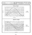
- FIGS. 2 to 5 are tables and graphs illustrating the effective stroke, reduction in effective flow, the relationship between piston stroke and crank angle, and the relationship between piston speed and crank angle, at stroke phase shifts of 0, 51.76, 120, and 180 degrees respectively, in one embodiment according to the present invention.
- the invention provides apparatus and methods for active stroke control for controlling fluid flow of multi-throw reciprocating pumps. Fluid flow is controlled by canceling out at least a portion of a discharge stroke of one plunger with a suction stroke of another plunger. Controlling the degree to which the discharge stroke is cancelled out is used to control the actual volume of fluid being pumped.
- pressure of plungers refers to two plungers each connected to their respective crankshafts, for example by means of cross-heads and connecting rods, and the crankshafts connected to each other by means of a differential gear arrangement in any known manner such that the phase of stroke may be varied between the two plungers.
- Compression chambers of the pair of plungers may be connected in any manner that provides minimal restriction to the flow of fluid between the compression chambers.
- FIG. 1 shows a schematic representation of a two-plunger reciprocating pump according to one embodiment of the invention.
- the pump features a phase control method of active stroke control, as described further below.
- FIG. 1 shows the pistons and cross-heads are shown as pistons acting upon the fluid. It will be understood by those with ordinary skill in the art that those pistons can be cross-heads that will then be connected to the actual plungers of the pump. In other embodiments cross-heads may be absent and the piston may directly connect to the connecting rod.
- Respective compression chambers of the pump are in fluid communication with each other through a fluid passage.
- the crankshaft of the pump is divided into a primary crankshaft and a secondary crankshaft.
- Each of the primary crankshaft and secondary crankshaft actuate one connecting rod and one piston (i.e., a plunger).
- the primary and secondary crankshafts are coupled by means of a differential, such as a differential gear assembly.
- the differential gear assembly is housed in a differential housing.
- the primary crankshaft is driven by a prime mover through an input flange for example.
- the primary crankshaft provides driving torque to the secondary crankshaft through the differential gear assembly.
- the differential housing is supported in differential housing bearings in such a manner that it may be rotated in a controlled manner around an axis common with the crankshaft, i.e., the crankshaft axis.
- the rotation means (not shown) used to control such movement may be one of any number of mechanisms known to those of ordinary skill in the art.
- rotation means may include a worm gear coupled to the differential housing and driven by a motor or the like.
- the two throws of the crankshaft are in phase in FIG. 1 , meaning that the two plungers will travel in synchrony between top dead centre (TDC) and bottom dead centre (BDC).
- TDC top dead centre
- BDC bottom dead centre
- the primary and secondary crankshafts will rotate in opposite directions, but the plungers will reach TDC and BDC at the same time.
- pressures above the plungers will be substantially the same, and thus no transfer of fluid between the two compression chambers will occur. All of the fluid will be forced out through the discharge valves. This situation will correspond to maximum flow of the pump, and is described graphically in FIG. 2 with respect to one embodiment of the invention. Since there are two plungers, the effective stroke will be equal to twice the actual stroke of each plunger and the total effective speed will be equal to twice the actual speed of each plunger.
- the differential housing may be rotated away from the in phase position, around the crankshaft axis, and then held in a new angular position to effect a “phase shift” between the two plungers.
- the phase shift will be equal to twice the angle of the rotation of the housing. For example, to achieve a 50 degree phase shift, the differential housing must be rotated by 25 degrees.
- FIGS. 3 and 4 graphically describe reduction of effective flow with phase shifts of 51.67 and 120 degrees respectively. Maximum reduction of effective flow occurs with a phase shift of 180 degrees, where very little fluid will flow out the discharge valves, as graphically described in FIG. 5 .
- a phase shift of 180 degrees does not result in 100% flow reduction because the actual percentage of flow reduction will depend on pump geometry, in particular the ratio of connecting rod length to crank throw length (i.e., crank radius). The ratio of connecting rod length to crank throw length is positively correlated with the actual percentage of flow reduction.
- phase shifting merely requires rotation of the differential housing about the crankshaft axis, simple and uninterrupted flow control is achieved. Once a desired effective flow is achieved, the differential housing may for example be locked in that angular position until further adjustment is required.
Abstract
Description
-
- changing the liner/plunger size, since liners and plungers of smaller diameter fill provide for less flow per stroke of the pump and vice versa,
- changing the speed of the pump, since slowing down the pump will result in fewer “strokes per minute” which will result in less flow of fluid and vice versa.
-
- Pumps with an even number of plungers higher than 2 (4, 6, 8, etc.) may be controlled by providing one or more “pairs” of plungers; and
- Pumps with an odd number of plungers (3, 5, 7, etc.) may be controlled by “pairing” some plungers for control while leaving one or more plungers uncontrolled (e.g. always acting at full-flow).
Claims (7)
Priority Applications (1)
| Application Number | Priority Date | Filing Date | Title |
|---|---|---|---|
| US13/215,926 US8943950B2 (en) | 2010-08-24 | 2011-08-23 | Reciprocating pump flow control |
Applications Claiming Priority (2)
| Application Number | Priority Date | Filing Date | Title |
|---|---|---|---|
| US37660610P | 2010-08-24 | 2010-08-24 | |
| US13/215,926 US8943950B2 (en) | 2010-08-24 | 2011-08-23 | Reciprocating pump flow control |
Publications (2)
| Publication Number | Publication Date |
|---|---|
| US20120210865A1 US20120210865A1 (en) | 2012-08-23 |
| US8943950B2 true US8943950B2 (en) | 2015-02-03 |
Family
ID=45724145
Family Applications (1)
| Application Number | Title | Priority Date | Filing Date |
|---|---|---|---|
| US13/215,926 Active 2033-06-18 US8943950B2 (en) | 2010-08-24 | 2011-08-23 | Reciprocating pump flow control |
Country Status (2)
| Country | Link |
|---|---|
| US (1) | US8943950B2 (en) |
| CA (1) | CA2750306C (en) |
Families Citing this family (1)
| Publication number | Priority date | Publication date | Assignee | Title |
|---|---|---|---|---|
| DE102015217313A1 (en) * | 2015-09-10 | 2017-03-16 | Provenion Gmbh | Apparatus and method for generating high-frequency and high-thrust pressure pulses and use of the pressure swing tester |
Citations (10)
| Publication number | Priority date | Publication date | Assignee | Title |
|---|---|---|---|---|
| US3672460A (en) * | 1971-02-16 | 1972-06-27 | Raygo Inc | Control means for power steering servo |
| US4228656A (en) * | 1978-05-19 | 1980-10-21 | Nasa | Power control for hot gas engines |
| US4240256A (en) * | 1979-01-31 | 1980-12-23 | Frosch Robert A | Phase-angle controller for stirling engines |
| US4808077A (en) * | 1987-01-09 | 1989-02-28 | Hitachi, Ltd. | Pulsationless duplex plunger pump and control method thereof |
| US4810168A (en) * | 1986-10-22 | 1989-03-07 | Hitachi, Ltd. | Low pulsation pump device |
| US4860702A (en) * | 1988-03-21 | 1989-08-29 | Doundoulakis George J | Compression ratio control in reciprocating piston engines |
| US6783331B2 (en) * | 2001-08-21 | 2004-08-31 | Petroleo Brasileiro S.A. - Petrobras | System and method of multiple-phase pumping |
| US20070148016A1 (en) * | 2005-12-22 | 2007-06-28 | Newport Medical Instruments, Inc. | Reciprocating drive apparatus and method |
| US20080101970A1 (en) * | 2006-10-25 | 2008-05-01 | Klaus Witt | Pumping apparatus having a varying phase relationship between reciprocating piston motions |
| US20090217904A1 (en) * | 2007-01-24 | 2009-09-03 | Lee Dae-Hee | Crankless reciprocating steam engine |
-
2011
- 2011-08-23 US US13/215,926 patent/US8943950B2/en active Active
- 2011-08-23 CA CA2750306A patent/CA2750306C/en active Active
Patent Citations (10)
| Publication number | Priority date | Publication date | Assignee | Title |
|---|---|---|---|---|
| US3672460A (en) * | 1971-02-16 | 1972-06-27 | Raygo Inc | Control means for power steering servo |
| US4228656A (en) * | 1978-05-19 | 1980-10-21 | Nasa | Power control for hot gas engines |
| US4240256A (en) * | 1979-01-31 | 1980-12-23 | Frosch Robert A | Phase-angle controller for stirling engines |
| US4810168A (en) * | 1986-10-22 | 1989-03-07 | Hitachi, Ltd. | Low pulsation pump device |
| US4808077A (en) * | 1987-01-09 | 1989-02-28 | Hitachi, Ltd. | Pulsationless duplex plunger pump and control method thereof |
| US4860702A (en) * | 1988-03-21 | 1989-08-29 | Doundoulakis George J | Compression ratio control in reciprocating piston engines |
| US6783331B2 (en) * | 2001-08-21 | 2004-08-31 | Petroleo Brasileiro S.A. - Petrobras | System and method of multiple-phase pumping |
| US20070148016A1 (en) * | 2005-12-22 | 2007-06-28 | Newport Medical Instruments, Inc. | Reciprocating drive apparatus and method |
| US20080101970A1 (en) * | 2006-10-25 | 2008-05-01 | Klaus Witt | Pumping apparatus having a varying phase relationship between reciprocating piston motions |
| US20090217904A1 (en) * | 2007-01-24 | 2009-09-03 | Lee Dae-Hee | Crankless reciprocating steam engine |
Also Published As
| Publication number | Publication date |
|---|---|
| US20120210865A1 (en) | 2012-08-23 |
| CA2750306A1 (en) | 2012-02-24 |
| CA2750306C (en) | 2018-03-06 |
Similar Documents
| Publication | Publication Date | Title |
|---|---|---|
| US20100303655A1 (en) | Reciprocating pump | |
| CA2818778C (en) | Variable radial fluid device with counteracting cams | |
| CA2818047C (en) | Variable radial fluid device with differential piston control | |
| US11434902B2 (en) | Electric diaphragm pump with offset slider crank | |
| US6976831B2 (en) | Transmissionless variable output pumping unit | |
| US8943950B2 (en) | Reciprocating pump flow control | |
| CN107044457A (en) | Pump control mechanism combination with power limit | |
| CN207728499U (en) | A kind of ten cylinder reciprocating pump of opposite opened | |
| CN108035856A (en) | A kind of ten cylinder reciprocating pump of opposite opened | |
| EP2083171A1 (en) | Fluid handling apparatus | |
| US2672819A (en) | Expansible-chamber and positivedisplacement type pump of variable capacity | |
| WO2015087337A1 (en) | Hydraulically operated but mechanically driven & mechanically reversed simple concrete pump | |
| CN211874669U (en) | Two-dimensional piston pump | |
| US11486372B2 (en) | Rotary barrel pump having separate guiding means and centering means for the barrel | |
| CA2818634C (en) | Variable radial fluid devices in series | |
| JP6338170B2 (en) | Fluid rotating machine | |
| CN207661084U (en) | A kind of reciprocal-rotary motion conversion mechanism and its water pump | |
| CN104454502B (en) | Plunger displacement pump | |
| RU2433302C1 (en) | Double-stage compressor plant | |
| EP3380754B1 (en) | Load cancelling hydrostatic system | |
| JP2015010514A (en) | Fluid rotary machine | |
| KR20120045832A (en) | Flow increase device using small hydraulic pump | |
| CN113464395A (en) | Two-dimensional piston pump | |
| GB2234786A (en) | Pump with two rotary cylinder blocks | |
| ITUB20155166A1 (en) | PISTON PUMPS with OPPOSED PISTONS |
Legal Events
| Date | Code | Title | Description |
|---|---|---|---|
| AS | Assignment |
Owner name: MIVA ENGINEERING LTD., CANADA Free format text: ASSIGNMENT OF ASSIGNORS INTEREST;ASSIGNORS:HARTONO, SOEGI;SCEKIC, VLADIMIR;TURNBULL, RUSSELL;REEL/FRAME:026894/0604 Effective date: 20110909 |
|
| AS | Assignment |
Owner name: MIVA ENGINEERING LTD., CANADA Free format text: CHANGE ASSIGNEE ADDRESS;ASSIGNOR:MIVA ENGINEERING LTD.;REEL/FRAME:034703/0373 Effective date: 20141218 |
|
| STCF | Information on status: patent grant |
Free format text: PATENTED CASE |
|
| AS | Assignment |
Owner name: DRILLFORM TECHNICAL SERVICES LTD., CANADA Free format text: ASSIGNMENT OF ASSIGNORS INTEREST;ASSIGNOR:MIVA ENGINEERING LTD.;REEL/FRAME:046052/0414 Effective date: 20180430 |
|
| MAFP | Maintenance fee payment |
Free format text: PAYMENT OF MAINTENANCE FEE, 4TH YR, SMALL ENTITY (ORIGINAL EVENT CODE: M2551) Year of fee payment: 4 |
|
| AS | Assignment |
Owner name: LONGBOW ENERGY SERVICES LP, CANADA Free format text: SECURITY INTEREST;ASSIGNOR:DRILLFORM TECHNICAL SERVICES LTD.;REEL/FRAME:048922/0961 Effective date: 20190212 Owner name: LONGBOW ENERGY SERVICES (INT.) LP, CANADA Free format text: SECURITY INTEREST;ASSIGNOR:DRILLFORM TECHNICAL SERVICES LTD.;REEL/FRAME:048923/0073 Effective date: 20190212 |
|
| AS | Assignment |
Owner name: LONGBOW ENERGY SERVICES LP, ALBERTA Free format text: SECURITY INTEREST;ASSIGNOR:DRILLFORM TECHNICAL SERVICES LTD.;REEL/FRAME:049155/0716 Effective date: 20190423 Owner name: LONGBOW ENERGY SERVICES (INT.) LP, ALBERTA Free format text: SECURITY INTEREST;ASSIGNOR:DRILLFORM TECHNICAL SERVICES LTD.;REEL/FRAME:049155/0771 Effective date: 20190423 Owner name: LONGBOW CAPITAL LIMITED PARTNERSHIP #22, ALBERTA Free format text: SECURITY INTEREST;ASSIGNOR:DRILLFORM TECHNICAL SERVICES LTD.;REEL/FRAME:049155/0846 Effective date: 20190423 Owner name: LONGBOW MANAGEMENT LIMITED PARTNERSHIP #22, ALBERT Free format text: SECURITY INTEREST;ASSIGNOR:DRILLFORM TECHNICAL SERVICES LTD.;REEL/FRAME:049155/0956 Effective date: 20190423 Owner name: LONGBOW CAPITAL (ANHOLT) LIMITED PARTNERSHIP #22, Free format text: SECURITY INTEREST;ASSIGNOR:DRILLFORM TECHNICAL SERVICES LTD.;REEL/FRAME:049155/0901 Effective date: 20190423 Owner name: LONGBOW MANAGEMENT LIMITED PARTNERSHIP #22, ALBERTA Free format text: SECURITY INTEREST;ASSIGNOR:DRILLFORM TECHNICAL SERVICES LTD.;REEL/FRAME:049155/0956 Effective date: 20190423 Owner name: LONGBOW CAPITAL (ANHOLT) LIMITED PARTNERSHIP #22, ALBERTA Free format text: SECURITY INTEREST;ASSIGNOR:DRILLFORM TECHNICAL SERVICES LTD.;REEL/FRAME:049155/0901 Effective date: 20190423 |
|
| AS | Assignment |
Owner name: HELMERICH & PAYNE INTERNATIONAL DRILLING CO., OKLAHOMA Free format text: SECURITY INTEREST;ASSIGNOR:DRILLFORM TECHNICAL SERVICES LTD.;REEL/FRAME:059958/0385 Effective date: 20220517 |
|
| MAFP | Maintenance fee payment |
Free format text: PAYMENT OF MAINTENANCE FEE, 8TH YR, SMALL ENTITY (ORIGINAL EVENT CODE: M2552); ENTITY STATUS OF PATENT OWNER: SMALL ENTITY Year of fee payment: 8 |