US8938182B2 - Stand of image forming apparatus and image forming apparatus having the same - Google Patents
Stand of image forming apparatus and image forming apparatus having the same Download PDFInfo
- Publication number
- US8938182B2 US8938182B2 US12/497,815 US49781509A US8938182B2 US 8938182 B2 US8938182 B2 US 8938182B2 US 49781509 A US49781509 A US 49781509A US 8938182 B2 US8938182 B2 US 8938182B2
- Authority
- US
- United States
- Prior art keywords
- unit
- plate member
- stand
- plate
- bent
- Prior art date
- Legal status (The legal status is an assumption and is not a legal conclusion. Google has not performed a legal analysis and makes no representation as to the accuracy of the status listed.)
- Expired - Fee Related, expires
Links
Images


Classifications
-
- G—PHYSICS
- G03—PHOTOGRAPHY; CINEMATOGRAPHY; ANALOGOUS TECHNIQUES USING WAVES OTHER THAN OPTICAL WAVES; ELECTROGRAPHY; HOLOGRAPHY
- G03G—ELECTROGRAPHY; ELECTROPHOTOGRAPHY; MAGNETOGRAPHY
- G03G15/00—Apparatus for electrographic processes using a charge pattern
-
- G—PHYSICS
- G03—PHOTOGRAPHY; CINEMATOGRAPHY; ANALOGOUS TECHNIQUES USING WAVES OTHER THAN OPTICAL WAVES; ELECTROGRAPHY; HOLOGRAPHY
- G03G—ELECTROGRAPHY; ELECTROPHOTOGRAPHY; MAGNETOGRAPHY
- G03G21/00—Arrangements not provided for by groups G03G13/00 - G03G19/00, e.g. cleaning, elimination of residual charge
- G03G21/16—Mechanical means for facilitating the maintenance of the apparatus, e.g. modular arrangements
- G03G21/1604—Arrangement or disposition of the entire apparatus
- G03G21/1619—Frame structures
-
- G—PHYSICS
- G03—PHOTOGRAPHY; CINEMATOGRAPHY; ANALOGOUS TECHNIQUES USING WAVES OTHER THAN OPTICAL WAVES; ELECTROGRAPHY; HOLOGRAPHY
- G03G—ELECTROGRAPHY; ELECTROPHOTOGRAPHY; MAGNETOGRAPHY
- G03G21/00—Arrangements not provided for by groups G03G13/00 - G03G19/00, e.g. cleaning, elimination of residual charge
- G03G21/16—Mechanical means for facilitating the maintenance of the apparatus, e.g. modular arrangements
-
- G—PHYSICS
- G03—PHOTOGRAPHY; CINEMATOGRAPHY; ANALOGOUS TECHNIQUES USING WAVES OTHER THAN OPTICAL WAVES; ELECTROGRAPHY; HOLOGRAPHY
- G03G—ELECTROGRAPHY; ELECTROPHOTOGRAPHY; MAGNETOGRAPHY
- G03G2215/00—Apparatus for electrophotographic processes
- G03G2215/00004—Handling of entire apparatus
- G03G2215/00012—Upright positioning as well as horizontal positioning for image forming
-
- G—PHYSICS
- G03—PHOTOGRAPHY; CINEMATOGRAPHY; ANALOGOUS TECHNIQUES USING WAVES OTHER THAN OPTICAL WAVES; ELECTROGRAPHY; HOLOGRAPHY
- G03G—ELECTROGRAPHY; ELECTROPHOTOGRAPHY; MAGNETOGRAPHY
- G03G2221/00—Processes not provided for by group G03G2215/00, e.g. cleaning or residual charge elimination
- G03G2221/16—Mechanical means for facilitating the maintenance of the apparatus, e.g. modular arrangements and complete machine concepts
- G03G2221/1678—Frame structures
Definitions
- the present general inventive concept relates to a stand of an image forming apparatus and an image forming apparatus having the same, and more particularly, to a stand of an image forming apparatus and an image forming apparatus having the same that reduces a manufacturing cost.
- An image forming apparatus includes a printing engine to form an image on a printing medium, and a stand to support the printing engine.
- the size of the printing engine varies according to the type of the image forming apparatus, and the size of the stand varies to correspond thereto. Accordingly, since the type of the stand may be as varied as the number of models of the printing engine, the manufacturing cost thereof may increase.
- the printing engine seated on the stand may weigh more than 100 kg, and it is important that the stand has a configuration which is capable of stably supporting the weight.
- the present general inventive concept provides a stand of an image forming apparatus and an image forming apparatus having the same, which can reduce the manufacturing cost thereof.
- the present general inventive concept also provides a stand of an image forming apparatus and an image forming apparatus having the same which is capable of stably supporting a printing engine.
- the present general inventive concept also provides a stand of an image forming apparatus and an image forming apparatus having the same which is capable of being conveniently transported to an installation site.
- the present general inventive concept provides a stand of an image forming apparatus and an image forming apparatus having the same which is capable of being conveniently assembled and disassembled.
- a stand of an image forming apparatus including a first plate member which includes a first surface unit which forms an external appearance, and a first bent unit which is provided to at least one of the opposite end parts of the first surface unit, and at least one plate unit which includes a second plate member which includes a second surface unit and a second bent unit which is provided to at least one of the opposite end parts of the second surface unit, the second plate member capable of being inserted into the first plate member, and at least one of the first bent unit and the second bent unit being bent so that each bending direction thereof may start from at least one of the first surface unit and the second surface unit and bend toward at least one of the first surface unit and the second surface unit.
- the second bent unit may be capable of being inserted into an inner part of the first bent unit.
- At least one pair of the first surface unit and the first bent unit and the second surface unit and the second bent unit may be integrally formed.
- the first plate member may be slidingly movable in a lengthwise direction of the first bent unit or the second bent unit with respect to the second plate member.
- the stand of the image forming apparatus may further include a position settling unit which settles a position of the second plate member in a position into which the second plate member slides with respect to the first plate member.
- the position settling unit may include first and second thru holes which are respectively formed to the first bent unit and the second bent unit which face each other, and a coupling unit which is inserted to the first and second thru holes to couple the first bent unit and the second bent unit.
- At least one of the first and second thru holes may be a plurality of thru holes provided in the lengthwise direction of the bent unit to permit adjustment of a relative position between the first plate member and the second plate member.
- the at least one plate unit may further include a third plate member which includes a third surface unit which forms an external appearance, and a third bent unit which is bent from the third surface unit.
- the second plate member may be interposed between the first plate member and the third plate member, and is capable of being inserted into the first plate member and the third plate member.
- the third plate member may be provided to be compatible with the first plate member.
- the third bent unit may be bent so that a bending direction thereof may start from the third surface unit, and bend toward the third surface unit.
- the second bent unit may be capable of being inserted to an inner part of the first bent unit and the third bent unit.
- the second plate member may be slidingly movable in a lengthwise direction of the first bent unit or the third bent unit with respect to at least one of the first plate member and the third plate member.
- the stand of the image forming apparatus may further include a position settling unit which settles a position of the second plate member with respect to at least one of the first plate member and the third plate member.
- the plate unit may include an upper plate unit and a lower plate unit which face a lower side of the image forming apparatus, and are disposed at a distance from each other, and a left plate unit and a right plate unit which connect the upper and lower plate units.
- the upper and lower plate units may respectively include first and second plate members, and at least one of the first plate member and the second plate member may be slidingly movable to allow a width adjustment.
- the left and right plate units may respectively include the first and second plate members, and at least one of the first plate member and the second plate member may be slidingly movable to allow a height adjustment.
- the plate unit may include a lower plate unit which faces a lower part of the image forming apparatus.
- the lower plate unit may include the first and second plate members, and at least one of the first plate member and the second plate member is slidingly movable to allow a width adjustment.
- an image forming apparatus including a printing engine which forms an image on a printing medium and a stand to support the printing engine, which may include a first plate member which includes a first surface unit which forms an external appearance, and a first bent unit which is provided to at least one of the opposite end parts of the first surface unit, and at least one plate unit which includes a second plate member which includes a second surface unit and a second bent unit which is provided to at least one of the opposite end parts of the second surface unit, the second plate member capable of being inserted into the first plate member, and at least one of the first bent unit and the second bent unit being bent so that each bending direction thereof may start from at least one of the first surface unit and the second surface unit and bend toward at least one of the first surface unit and the second surface unit.
- a stand of an image forming apparatus including a lower plate unit including a first plate member and a second plate member, the second plate member including a bent portion to receive the first plate member, and an upper plate unit connected to the lower plate unit to provide a support surface for the image forming apparatus.
- the first plate member may have a bent portion which is received by the bent portion of the second plate member.
- the upper plate member may further include a first upper plate member and a second upper plate member, the second upper plate member having a bent portion to receive the first upper plate member.
- the stand may further include a side unit disposed between the lower plate unit and the upper plate unit including a first side unit member and a second side unit member, the second site unit member having a bent portion to receive the first side unit member.
- At least one of the lower plate unit, the upper plate unit, and the side unit may include a position settling unit to permit a relative position of the first plate member and the second plate member, the first upper plate member and the second upper plate member, and the first side unit member and the second side unit member, respectively, to be fixed.
- a surface of the bent portion of the second plate member may face a surface of the second plate member.
- the second plate member may include a surface unit and a bent portion, wherein the bent portion is bent such that a surface of the bent portion faces a surface of the surface unit.
- the second plate member may include a surface unit and a bent portion, wherein the bent portion is a predetermined distance from the surface unit to permit the first plate member to be received by the second plate member.
- a stand of an image forming apparatus including a lower plate unit including a first lower plate member and a second lower plate member each comprising a plurality of bent portions such that the second lower plate member may slidingly accommodate the first lower plate member, and an upper plate unit to connect with the lower plate unit, including a first upper plate member and a second upper plate member each comprising a plurality of bent portions such that the second upper plate member may slidingly accommodate the first upper plate member.
- the stand may further include a side unit, disposed in between the lower plate unit and the upper plate unit, including a first side member and a second side member each comprising a plurality of bent portions such that the second side member may slidingly accommodate the first side member.
- the relative positions of at least the first lower plate member and the second lower plate member, and the first upper plate member and the second upper plate member, may be fixed with a position settling unit to determine a width of the stand.
- the relative positions of the first side member and the second side member may be fixed with a position settling unit to determine a height of the stand.
- FIG. 1 illustrates a perspective view of an image forming apparatus according to a first exemplary embodiment of the present general inventive concept
- FIG. 2 illustrates a perspective view of a knockdown stand of the image forming apparatus in FIG. 1 ;
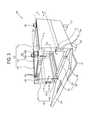
- FIG. 3 is a perspective view illustrating a state of opening a cover of the knockdown stand in FIG. 2 ;
- FIG. 4 illustrates a planar exploded perspective view of the knockdown stand in FIG. 2 ;
- FIG. 5 illustrates a side exploded perspective view of the knockdown stand in FIG. 2 ;
- FIG. 6 illustrates a main portion perspective view for describing a width adjustment of the knockdown stand in FIG. 2 ;
- FIG. 7 illustrates a main portion perspective view for describing a height adjustment of the knockdown stand in FIG. 2 ;
- FIG. 8 illustrates a main portion perspective view of the knockdown stand in FIG. 2 ;
- FIG. 9 illustrates a main portion perspective view of a reinforcing member reinforcing an edge of an upper plate unit of the knockdown stand in FIG. 2 ;
- FIG. 10 illustrates a main portion perspective view of a reinforcing member reinforcing a central part of the upper plate unit of the knockdown stand in FIG. 2 ;
- FIG. 11 illustrates a main portion perspective view of a reinforcing member reinforcing an edge of a lower plate unit of the knockdown stand in FIG. 2 ;
- FIG. 12 illustrates a rear perspective view of the knockdown stand in FIG. 2 ;
- FIG. 13 illustrates a front perspective view of the knockdown stand in FIG. 2 ;
- FIG. 14 illustrates an exploded perspective view of a knockdown stand of an image forming apparatus according to a second exemplary embodiment of the present general inventive concept
- FIG. 15 illustrates an assembling completion view of the knockdown stand in FIG. 14 ;
- FIG. 16 illustrates an enlarged sectional view taken along line A-A of the knockdown stand in FIG. 3 ;
- FIG. 17 illustrates an enlarged sectional view taken along line H-H of the knockdown stand in FIG. 3 .
- an image forming apparatus 1 includes a printing engine 200 , and a knockdown stand of an image forming apparatus 100 supporting the printing engine 200 .
- the printing engine 200 may include a scanning unit (not shown) to scan an image of a document, and a printing unit (not shown) to print a scanned image on a printing medium.
- the printing unit may print an image on a printing medium by at least one of a electrophotographic type, an ink jet type and a heat transferring type.
- the knockdown stand 100 includes a pair of front rollers 102 and a pair of rear rollers 103 provided to a lower side thereof to easily move the image forming apparatus 1 , a cover 104 openable at a front side, and a pair of overturn preventing plates 101 disposed between the front rollers 102 and the rear rollers 103 to prevent the image forming apparatus 1 from being overturned in a forward or backward direction.
- a first end part of the overturn preventing plate 101 is connected to a lower part of the knockdown stand 100 , and a second end part thereof extends toward a bottom surface on which the knockdown stand 100 is installed.
- the overturn preventing plate 101 is detachably disposed to the knockdown stand 100 .
- a part or all of the cover 104 , the rollers 102 and 103 and the overturn preventing plate 101 may be omitted as necessary.
- FIGS. 2 and 3 are, respectively, a perspective view of the knockdown stand 100 of the image forming apparatus, and a perspective view of the knockdown stand 100 in which the cover 104 is opened.
- Reference numeral 105 in FIG. 3 refers to installation mounts which permit detachably installing the printing engine 200 to the knockdown stand 100 , and which protrude from an upper plate unit 110 .
- the printing engine 200 has a recessed unit in a position corresponding to the installation mount 105 , and the printing engine 200 and the installation mount 105 are prevented from being separated from each other by a coupling pin 105 a.
- the knockdown stand 100 of the image forming apparatus includes the upper plate unit 110 , a lower plate unit 150 , a left plate unit 120 and a right plate unit 130 .
- the upper plate unit 110 may include a first plate member 111 , a second plate member 113 and a third plate member 115 .
- the left plate unit 120 may include a first plate member 121 and a second plate member 123 .
- the right plate unit 130 may include a first plate member 131 and a second plate member 133 .
- the lower plate unit 150 may include a first plate member 151 , a second plate member 153 and a third plate member 155 .
- FIG. 16 is a sectional view taken along line A-A of FIG. 3 .
- the first plate members 111 , 121 , 131 and 151 (hereinafter, referred to 111 ) and the second plate members 113 , 123 , 133 and 153 (hereinafter, referred to 113 ) respectively include first surface units 111 e, 121 e, 131 e and 151 e (hereinafter, referred to 111 e ) and first bent units 111 a, 111 b, 121 a, 121 b, 131 a, 131 b, 151 a and 151 b (hereinafter, referred to 111 a ), and second surface units 113 e, 123 e, 133 e and 153 e (hereinafter, referred to 113 e ) and second bent units 113 a, 113 b, 123 a, 123 b, 133 a, 133 b, , 133 b
- the first bent unit 111 a is provided at opposite end parts of the first surface unit 111 e forming an external appearance. Also, the first bent unit 111 a is bent to have a bending direction B thereof which starts from the first surface unit 111 e and bends toward the first surface unit 111 e again. Also, the first bent unit 111 a is provided so that there exists an interval G between an end part E of the first bent unit 111 a and the first surface unit 111 e.
- the interval G is bigger than the thickness t of the second surface unit 113 e of the second plate member 113 . Accordingly, the second surface unit 113 e of the second plate member 113 is capable of passing through the interval G. Also, the first bent unit 111 a can accommodate the second bent unit 113 a therein, that is, to allow the second bent unit 113 a to be inserted thereinto. Accordingly, the second plate member 113 may be inserted to the first plate member 111 . Also, the second plate member 113 may slidingly move when inserted into the first plate member 111 .
- the second bent unit 113 a is provided at opposite end parts of the second surface unit 113 e.
- the second bent unit 113 a may also not be provided to the opposite end parts of second surface unit 113 e as necessary.
- the second bent unit 113 a provided to the opposite end parts of second surface unit 113 e is illustrated to have a section symmetrical with respect to a central line C.
- the second bent unit 113 a may be provided to have an unsymmetrical section.
- the second bent unit 113 a is bent to have a bending direction B which starts from the second surface unit 113 e and then bends toward the second surface unit 113 e again.
- the bending directions of the first bent unit 111 a and the second bent unit 113 a are illustrated to be the same, but alternatively, the bending directions may be different.
- the knockdown stand 100 of the image forming apparatus further includes a position settling unit 140 to settle the positions of the first plate member 111 and the second plate member 113 .
- the position settling unit 140 includes a first thru hole 141 and a second thru hole 142 respectively formed through the first bent unit 111 a and the second bent unit 113 a, and a coupling unit 145 penetrating the first and second thru holes 141 and 142 to be coupled.
- the coupling unit 145 may be provided as a bolt and a nut.
- At least one of the first thru hole 141 and the second thru hole 142 may be provided in plural in a lengthwise direction of the first bent unit 111 a or the second bent unit 113 a. Accordingly, a relative position of the first plate member 111 and the second plate member 113 may be adjusted. That is, as shown in FIG. 3 , since three second thru holes 142 of the second plate members 123 and 133 of the left and right plate units 120 and 130 are formed (one of them is formed to a position in which the coupling unit 145 is disposed), a relative position adjustment between the first plate member 121 and 131 and the second plate member 123 and 133 allows three steps.
- the number of thru holes, and thus the number of steps, is not limited, and may be greater or less than three.
- the position of the first plate member 121 and 131 and the second plate member 123 and 133 shown in FIG. 3 is illustrated in a position making the height of the knockdown stand 100 highest.
- the first and second plate members 111 and 113 may be manufactured out of a metal plate having a predetermined thickness by sheet metal forming so that the first bent unit 111 a and the second bent unit 113 a can be formed.
- the first and second plate members 111 and 113 may be manufactured by injection molding, or by coupling several components.
- first bent unit 111 a and the first surface unit 111 e, or the second bent unit 113 a and the second surface unit 113 e may be integrally provided.
- the first and second plate members 111 and 113 are designed to bear an axial load which is transmitted in a lengthwise direction of the bent unit. Also, since each section of the first and second plate members 111 and 113 has an approximately I shape, the bending strength thereof is great.
- first and second plate members 111 and 113 can be manufactured out of a metal plate by sheet metal forming, thereby reducing the weight thereof.
- FIG. 17 is a sectional view taken along line H-H of the knockdown stand 100 in FIG. 3 .
- the third plate member 115 of the upper plate unit 110 and the third plate member 155 of the lower plate unit 150 respectively include third surface units 115 e and 155 e and third bent units 115 a, 115 b, 155 a and 155 b.
- the third bent units 115 a, 115 b, 155 a and 155 b are bent to have bending directions D which start from the first surface units 115 e and 155 e and then bend toward the first surface units 115 e and 155 e again.
- the third plate member 115 of the upper plate unit 110 and the third plate member 155 of the lower plate unit 150 are provided so that the second plate member 113 of the upper plate unit 110 can be inserted thereinto like the first plate member 111 .
- the third bent units 115 a, 115 b, 155 a and 155 b accommodate the second bent units 113 a and 153 a of the second plate members 113 and 153 of the upper and lower plate units 110 and 150
- the second surface units 113 e and 153 e of the second plate members 113 and 153 are provided to penetrate between the third bent units 115 a, 115 b, 155 a and 155 b and the third surface units 115 e and 155 e. Accordingly, the second plate member 113 may be inserted into the third plate member 115 , and they may slidingly move in the inserted state.
- the third plate member 115 of the upper plate unit 110 may be symmetrical with the first plate member 111 of the upper plate unit 110 to interpose the second plate member 113 therebetween. That is, the first plate member 111 and the third plate member 115 of the upper plate unit 110 are compatible with each other. Accordingly, if two first plate members 111 are manufactured, one of them may be used as the third plate member 115 .
- FIGS. 4 to 8 are exploded views illustrating a main portion of the knockdown stand 100 of the image forming apparatus.
- the upper and lower plate units 110 and 150 are assembled as the second plate members 113 and 153 are inserted into the first plate members 111 and 151 and the third plate members 115 and 155 .
- the left and right plate units 120 and 130 are assembled as the second plate members 123 and 133 are inserted to the first plate members 121 and 131 .
- the first plate members 111 and 151 and the third plate members 115 and 155 of the upper and lower plate units 110 and 150 respectively include sub bent units 111 c, 115 c, 151 c and 155 c bent from the first surface units 111 e and 151 e and the third surface units 115 e and 155 e to cover the first bent units 111 a and 151 a and the third bent units 115 a and 155 a.
- the first plate members 111 and 151 and the third plate members 115 and 155 of the upper and lower plate units 110 and 150 as well as the sub bent units 111 c, 115 c, 151 c and 155 c may be integrally formed by sheet metal forming. Accordingly, piece components of the first plate members 111 and 151 and the third plate members 151 and 155 may be further easily manufactured.
- the first thru hole 141 is formed through the first bent units 151 a and 151 b of the first plate member 151 of the lower plate unit 150
- the second thru hole 142 is formed through first sides of the second bent units 153 a and 153 b of the second plate member 153 .
- the third thru hole 143 is formed through second sides of the second bent units 153 a and 153 b of the second plate member 153
- the fourth thru hole 144 is formed through the third bent units 155 a and 155 b of the third plate member 155 .
- a single first thru hole 141 and a single fourth thru hole 144 are illustrated, and four second thru holes 142 and four third thru holes 143 are illustrated.
- the number thereof may vary, and may be the opposite, without limitation. Also, the number thereof may vary according to the number of adjustment steps to which the width w can be adjusted.
- the relative position of the first plate member 151 and the second plate member 153 may be adjusted by aligning one of the second thru holes 142 of the second plate member 153 with the first thru hole 141 , and then coupling them with the coupling unit 145 , as illustrated in FIG. 16 . Also, the relative position of the second plate member 153 and the third plate member 155 may be adjusted by aligning one of the third thru holes 143 of the second plate member 153 with the fourth thru hole 144 , and then coupling them with the coupling unit 145 , as illustrated in FIG. 17 .
- the width w of the lower plate unit 150 of the knockdown stand 100 of the image forming apparatus may be determined.
- the total width of the knockdown stand 100 of the image forming apparatus may be adjusted by adjusting the width of the upper plate unit 110 as described above with respect to the lower plate unit 150 .
- the knockdown stand 100 of the image forming apparatus may be adjusted in total sixteen width steps. However, this is no limitation to the number of steps which may be provided.
- the first thru hole 141 is formed through the first bent units 131 a and 131 b of the first plate member 131 of the right plate unit 130
- the second thru hole 142 is formed through the second bent units 133 a and 133 b of the second plate member 133 .
- the relative position of the first plate member 131 and the second plate member 133 may be adjusted by aligning the first thru hole 141 and the second thru hole 142 , and then coupling them with the coupling unit 145 in FIG. 16 .
- the left plate unit 120 is provided similarly to the right plate unit 130 so that the relative position of the first plate member 121 and the second plate member 123 may be adjusted.
- the height h of the knockdown stand 100 of the image forming apparatus may be adjusted. Since three second thru holes 142 are formed through the left and right plate units 130 , the height h may be adjusted in three steps. However, this is no limitation to the number of steps which may be provided and if more steps or smaller steps to adjust the height h are desired, the number of the second thru holes 142 formed through the left and right plate units 130 may be increased and/or formed more closely together.
- the upper plate unit 110 and the left and right plate units 120 and 130 (precisely, the first plate members 121 and 131 of the left and right plate units 120 and 130 ) of the knockdown stand 100 of the image forming apparatus may be coupled with each other by welding.
- the first plate member 111 of the upper plate unit 110 and the first plate member 131 of the right plate unit 130 may be coupled to each other by welding. They may be welded along a contact part J in which the first plate member 111 of the upper plate unit 110 and the first plate member 131 of the right plate unit 130 contact each other.
- the third plate member 115 of the upper plate unit 110 and the first plate member 121 of the left plate unit 120 may be welded along a contact part J in which they contact each other like the first plate member 111 of the upper plate unit 110 .
- the lower plate unit 150 and the left and right plate units 120 and 130 (precisely, the second plate members 123 and 133 of the left and right plate units 120 and 130 ) of the knockdown stand 100 of the image forming apparatus may be coupled with each other by welding.
- the first plate member 151 of the lower plate unit 150 and the second plate member 133 of the right plate unit 130 may be coupled to each other by welding. They may be welded along a contact portion in which the first plate member 151 of the lower plate unit 150 and the second plate member 133 of the right plate unit 130 contact each other.
- the third plate member 155 of the lower plate unit 150 and the second plate member 123 of the left plate unit 120 may be welded along a contact part M in which they contact each other similar to the first plate member 151 of the lower plate unit 150 .
- the volume thereof may be minimized during being moved by the following method.
- each second plate member 113 and 153 of the upper plate unit 110 and the lower plate unit 150 is detachably coupled with the first plate members 111 and 151 and the third plate members 115 and 155 by coupling unit (for example, a bolt and nut), the second plate members 113 and 153 can be moved to an installation site in a piece component state.
- coupling unit for example, a bolt and nut
- first plate member 111 of the upper plate unit 110 and the first plate member 131 of the right plate unit 130 coupled by welding may be moved in a previously-welded state.
- the other components coupled by welding that is, the third plate member 115 of the upper plate unit 110 and the first plate member 121 of the left plate unit 120 , the first plate member 151 of the lower plate unit 150 and the second plate member 133 of the right plate unit 130 , and the third plate member 155 of the lower plate unit 150 and the second plate member 123 of the left plate unit 120 also may be moved to the installation site in a previously-welded state.
- four previously welded assembling components having an approximate L shape and two second plate members 113 and 153 can be moved to an installation site in a separated state, and then can be assembled at the installation site. Accordingly, the volume thereof may be minimized during moving.
- any one may conveniently assemble and install stand 100 at the installation site.
- the first plate member 151 and the third plate member 155 of the lower plate unit 150 may further include roller installing units 151 f and 155 f provided to install the front rollers 102 and the rear rollers 103 .
- the roller installing units 151 f and 155 f may protrude toward the rollers 102 and 103 from the first surface unit 151 e and the third surface unit 155 e to increase strength.
- the first plate members 111 and 151 and the third plate members 115 and 155 of the upper and lower plate units 110 and 150 may further include guide protrusions 111 d, 151 d, 115 d and 155 d.
- the second plate members 113 and 153 of the upper and lower plate units 110 and 150 may further include guide grooves 113 c and 153 c extending in lengthwise directions of the second bent units 113 a, 113 b, 153 a and 153 b.
- the guide protrusions 111 d, 151 d, 115 d and 155 d are accommodated to the guide grooves 113 c and 153 c to be guided along the guide grooves 113 c and 153 c.
- the first plate members 111 and 151 and the third plate members 115 and 155 of the upper and lower plate units 110 and 150 may smoothly slide against the second plate members 113 and 153 .
- FIGS. 9 to 13 are perspective views illustrating a reinforcing member disposed to reinforce the knockdown stand 100 of the image forming apparatus.
- a reinforcing angle 171 may be disposed to a boundary edge of the upper plate unit 110 and the left and right plate units 120 and 130 .
- the reinforcing angle 171 may have a section of an L shape, and may be disposed to a boundary surface between the first surface unit 111 e in FIG. 8 of the first plate member 111 of the upper plate unit 110 and the sub bent unit 111 c in FIG. 8 .
- the reinforcing angle 171 may be coupled to the first plate member 111 by a coupling unit such as a rivet or any other coupling unit.
- the reinforcing angle 171 may be moved to an installation site in the state that the reinforcing angle 171 is coupled to the first plate member 111 .
- a stiffener 173 for reinforcing the second surface unit 113 e of the second plate member 113 of the upper plate unit 110 may be disposed.
- the stiffener 173 may be disposed in parallel with the lengthwise direction of the second bent unit 113 a, and the cross-section thereof may have at least one of a hat shape, an L shape and a C shape.
- the sectional shape is not particularly limited, and may vary as long as stiffener 173 reinforces the second plate member 113 .
- the stiffener 173 may further include a flange 173 a coupled to the second surface unit 113 e by a coupling unit such as a rivet or any other coupling unit.
- the stiffener 173 may be transported assembled to the second plate 113 .
- FIG. 11 illustrates a corner reinforcing member 175 for reinforcing a corner portion between the left and right plate units 120 and 130 and the lower plate unit 150 .
- the corner reinforcing member 175 may have a cross-section of a hat shape, and may be coupled to the first surface unit 151 e of the first plate member 151 of the lower plate unit 150 .
- the corner reinforcing member 175 may be coupled by a coupling unit such as a rivet, or may be coupled by any other coupling unit.
- corner reinforcing member 175 may be similarly disposed to the third surface unit 155 e (illustrated in FIG. 8 ) of the third plate member 155 of the lower plate unit 150 .
- FIG. 12 illustrates lower reinforcing members 176 and 177 disposed to a lower surface of the lower plate unit 150 .
- a first lower reinforcing member 177 extends in opposite directions toward the first plate member 151 and the third plate member 153 along a lengthwise direction of the second bent unit 153 a of the second plate member 153 of the lower plate unit 150 .
- the first lower reinforcing member 177 is coupled to the second surface unit 153 e of the second plate member 153 , and the opposite sides 177 a thereof are distanced by a predetermined interval N from the second surface unit 153 e to prevent interference against the first and third plate members 151 and 153 as the first lower reinforcing member 177 extends toward the first plate member 151 and the third plate member 153 .
- the interval N is bigger than the thickness of the first and third plate members 151 and 153 .
- first plate member 151 and the third plate member 153 , and the first lower reinforcing member 177 may be prevented from interfering with each other.
- the first lower reinforcing member 177 may be respectively disposed two places to a front end part and a rear end part.
- the first lower reinforcing member 177 may further include a flange 177 b for being coupled to the second surface unit 153 e by a coupling unit such as a rivet.
- a second lower reinforcing member 176 is disposed to a lower surface of the second surface unit 153 e in a crossing direction with respect to the first lower reinforcing member 177 .
- the second lower reinforcing member 176 may include a flange 176 a coupled to the second surface unit 153 e by a coupling unit such as a rivet.
- the second lower reinforcing member 176 is illustrated to have a hat shape section in FIG. 12 , but the section may have various shapes.
- FIG. 13 illustrates a bottom reinforcing member 174 for reinforcing a bottom plate 160 .
- the bottom plate 160 is illustrated as an element of the knockdown stand 100 according to the present general inventive concept, but it may be omitted as necessary.
- the bottom plate 160 may be moved to an installation site in a piece component state, and may be detachably coupled to the bottom in the state that the upper and lower plate units 110 and 150 and the left and right plate units 120 and 130 are all coupled.
- the bottom plate 160 may be coupled to the knockdown stand 100 by an insertion coupling or an engagement coupling.
- the bottom reinforcing member 174 may extend in a height direction h as illustrated in FIGS. 7 and 13 along the bottom plate 160 .
- the bottom reinforcing member 174 may be coupled to the bottom plate 160 by a coupling unit such as a rivet.
- the section thereof is illustrated to have a hat shape in FIG. 13 , but other shape sections may be employed as necessary.
- the above reinforcing members which are the reinforcing angle 171 , the stiffener 173 , the corner reinforcing member 175 , the first lower reinforcing member 177 , the second lower reinforcing member 176 and the bottom reinforcing member 174 may be all moved to an installation site coupled to each piece component.
- the height h and width w of the knockdown stand 100 of the image forming apparatus are capable of being adjusted, and these are determined appropriately to a model of the printing engine 200 . That is, if the model of the printing engine 200 is different and the width w and height h thereof are to be different, the knockdown stand 100 may be commonly used with a plurality of printing engines 200 without the necessity of making numerous separate stands. Accordingly, a manufacturing cost of the image forming apparatus 1 may be reduced.
- the cover 104 and the bottom plate 160 may employ other kinds according to the model of the printing engine 200 .
- the cover 104 and the bottom plate 160 may employ other kinds according to the model of the printing engine 200 .
- an inner space of the knockdown stand 100 may accommodate a toner cartridge, an ink cartridge or other expendables.
- a cover installing angle 181 is disposed to the first plate member 151 and the third plate member 153 of the lower plate unit 150 .
- a hinge pivot 183 is disposed to the cover installing angle 181 .
- the cover 104 is rotatably disposed about the hinge pivot 183 .
- the cover 104 may be formed of a plastic material.
- the upper plate unit 110 and the lower plate unit 150 are illustrated to respectively include three plate members 111 , 113 and 115 , and 151 , 153 and 155 .
- the upper plate unit 110 and the lower plate unit 150 may include only two plate members, that is, first plate members 111 and 151 and second plate members 153 and 155 .
- FIGS. 14 and 15 a knockdown stand 100 a for an image forming apparatus according to a second exemplary embodiment of the present general inventive concept will be described by referring to FIGS. 14 and 15 .
- the knockdown stand 100 a of the image forming apparatus according to the second exemplary embodiment of the present general inventive concept includes an upper plate unit 110 a and a lower plate unit 150 .
- the knockdown stand 100 according to the first exemplary embodiment is a large size knockdown stand including the left and right plate units 120 and 130 , but the knockdown stand 100 a according to the second exemplary embodiment is a small size knockdown stand.
- the upper plate unit 110 a has an L shape section, and is disposed to an upper side of the lower plate unit 150 to cover the lower plate unit 150 .
- An installation mount 105 for installing a printing engine 200 is disposed to an upper part of upper plate unit 110 a.
- the lower plate unit 150 according to the present exemplary embodiment may have the same configuration as the lower plate unit 150 according to the first exemplary embodiment describe above.
- the width w of the knockdown stand 100 a of the image forming apparatus may be adjusted by the lower plate unit 150 .
- a manufacturing cost may be reduced.
- the height and width of the stand may be adjusted according to a model of a printing engine, thereby superiorly reducing a manufacturing cost in comparison to manufacturing a knockdown stand by each model.
- the weight of the printing engine may be stably supported.
- the total thereof is disassembled just by uncoupling a coupling unit, and the total thereof is assembled just by coupling the coupling unit, thereby permitting convenient assembly and disassembly.
Landscapes
- Physics & Mathematics (AREA)
- General Physics & Mathematics (AREA)
- Electrophotography Configuration And Component (AREA)
Abstract
Description
Claims (25)
Applications Claiming Priority (3)
| Application Number | Priority Date | Filing Date | Title |
|---|---|---|---|
| KR1020080070217A KR101292560B1 (en) | 2008-07-18 | 2008-07-18 | Stand for image forming apparatus and image forming apparatus including the same |
| KR10-2008-0070217 | 2008-07-18 | ||
| KR2008-70217 | 2008-07-18 |
Publications (2)
| Publication Number | Publication Date |
|---|---|
| US20100014886A1 US20100014886A1 (en) | 2010-01-21 |
| US8938182B2 true US8938182B2 (en) | 2015-01-20 |
Family
ID=41530406
Family Applications (1)
| Application Number | Title | Priority Date | Filing Date |
|---|---|---|---|
| US12/497,815 Expired - Fee Related US8938182B2 (en) | 2008-07-18 | 2009-07-06 | Stand of image forming apparatus and image forming apparatus having the same |
Country Status (2)
| Country | Link |
|---|---|
| US (1) | US8938182B2 (en) |
| KR (1) | KR101292560B1 (en) |
Families Citing this family (12)
| Publication number | Priority date | Publication date | Assignee | Title |
|---|---|---|---|---|
| CN101295149B (en) * | 2007-04-24 | 2011-03-02 | 京瓷美达株式会社 | Image forming apparatus |
| JP5100763B2 (en) * | 2010-01-19 | 2012-12-19 | シャープ株式会社 | Document reading apparatus and image forming apparatus having the same |
| JP5823168B2 (en) * | 2011-05-24 | 2015-11-25 | 太陽誘電株式会社 | Communication module |
| US9411301B2 (en) * | 2014-01-31 | 2016-08-09 | Canon Kabushiki Kaisha | Frame for image forming apparatus and manufacturing method thereof |
| JP6403579B2 (en) * | 2015-01-15 | 2018-10-10 | キヤノン株式会社 | Structure of image forming apparatus |
| JP6550956B2 (en) * | 2015-06-22 | 2019-07-31 | 富士ゼロックス株式会社 | Image forming device |
| JP6645686B2 (en) * | 2015-08-28 | 2020-02-14 | キヤノン株式会社 | Image forming device |
| JP6758600B2 (en) * | 2016-07-04 | 2020-09-23 | 富士ゼロックス株式会社 | Image forming device |
| JP6932514B2 (en) * | 2017-02-20 | 2021-09-08 | キヤノン株式会社 | Device frame and image forming device equipped with this |
| JP2018151609A (en) * | 2017-03-10 | 2018-09-27 | 京セラドキュメントソリューションズ株式会社 | Support mechanism and image forming apparatus |
| JP7566487B2 (en) | 2020-05-11 | 2024-10-15 | キヤノン株式会社 | Anti-tip device, sheet feeding device and image forming apparatus |
| JP7691220B2 (en) | 2020-09-15 | 2025-06-11 | キヤノン株式会社 | Image forming device |
Citations (7)
| Publication number | Priority date | Publication date | Assignee | Title |
|---|---|---|---|---|
| US2739776A (en) * | 1953-08-14 | 1956-03-27 | Louis M Terando | Adjustable and expanding pallet |
| US5080320A (en) * | 1990-12-19 | 1992-01-14 | Walter Chieng | Adjustable computer printer stand |
| JP2000044111A (en) * | 1998-07-30 | 2000-02-15 | Mita Ind Co Ltd | Finisher mounting table |
| US20020098008A1 (en) * | 2001-01-22 | 2002-07-25 | Susumu Tashiro | Mainframe structure of image forming apparatus |
| US20040079855A1 (en) * | 2002-10-23 | 2004-04-29 | Strabel William D. | Microfabrication tool pedestal and method of use |
| US20040247338A1 (en) * | 2003-03-31 | 2004-12-09 | Brother Kogyo Kabushiki Kaisha | Image forming unit and image forming apparatus having the same |
| US20060188304A1 (en) * | 2005-02-18 | 2006-08-24 | Ricoh Printing Systems, Ltd. | Printing apparatus |
-
2008
- 2008-07-18 KR KR1020080070217A patent/KR101292560B1/en not_active Expired - Fee Related
-
2009
- 2009-07-06 US US12/497,815 patent/US8938182B2/en not_active Expired - Fee Related
Patent Citations (7)
| Publication number | Priority date | Publication date | Assignee | Title |
|---|---|---|---|---|
| US2739776A (en) * | 1953-08-14 | 1956-03-27 | Louis M Terando | Adjustable and expanding pallet |
| US5080320A (en) * | 1990-12-19 | 1992-01-14 | Walter Chieng | Adjustable computer printer stand |
| JP2000044111A (en) * | 1998-07-30 | 2000-02-15 | Mita Ind Co Ltd | Finisher mounting table |
| US20020098008A1 (en) * | 2001-01-22 | 2002-07-25 | Susumu Tashiro | Mainframe structure of image forming apparatus |
| US20040079855A1 (en) * | 2002-10-23 | 2004-04-29 | Strabel William D. | Microfabrication tool pedestal and method of use |
| US20040247338A1 (en) * | 2003-03-31 | 2004-12-09 | Brother Kogyo Kabushiki Kaisha | Image forming unit and image forming apparatus having the same |
| US20060188304A1 (en) * | 2005-02-18 | 2006-08-24 | Ricoh Printing Systems, Ltd. | Printing apparatus |
Non-Patent Citations (2)
| Title |
|---|
| Korean Office Action dated Sep. 18, 2012 issued in KR Application No. 10-2008-0070217. |
| Office Action issued in KR Application No. 10-2008-0070217 dated Mar. 29, 2013. |
Also Published As
| Publication number | Publication date |
|---|---|
| KR101292560B1 (en) | 2013-08-12 |
| US20100014886A1 (en) | 2010-01-21 |
| KR20100009365A (en) | 2010-01-27 |
Similar Documents
| Publication | Publication Date | Title |
|---|---|---|
| US8938182B2 (en) | Stand of image forming apparatus and image forming apparatus having the same | |
| US5191382A (en) | Image forming system | |
| US8081899B2 (en) | Image forming apparatus having contacting members for contacting each other responsive to an external force when an opening/closing member is in closed position | |
| JP5152652B2 (en) | Structure and image forming apparatus | |
| EP2333619A2 (en) | Image forming apparatus | |
| US10990059B2 (en) | Metal frame of image forming apparatus and image forming apparatus | |
| WO2012066758A1 (en) | Combined device | |
| CN107077093B (en) | Structure of image forming apparatus | |
| US9531895B2 (en) | Multi-function device with image scanning unit and grip portion | |
| US20060017217A1 (en) | Paper tray supporting structure | |
| US11561501B2 (en) | Method of manufacturing metal frame of image forming apparatus | |
| CN100423622C (en) | Support structure of image forming apparatus | |
| US7113724B2 (en) | Tandem color image forming device | |
| KR102275198B1 (en) | Loader for transfer of vehicle parts | |
| US7578630B2 (en) | Control panel and apparatus using the same | |
| JP2002019973A (en) | Paper tray | |
| JP2022048895A (en) | Metal frame of image forming device and image forming device | |
| KR101090959B1 (en) | frame for collection box | |
| US20170346971A1 (en) | Imaging device assembly | |
| US12321125B2 (en) | Metal frame of image forming apparatus and image forming apparatus | |
| JP7625388B2 (en) | Image reading device and image forming device | |
| US20050129448A1 (en) | Printing media feeder of printing apparatus | |
| US20230058937A1 (en) | Cassette and printing apparatus | |
| US20070036601A1 (en) | Ink sheet cartridge | |
| JP4084361B2 (en) | Image forming apparatus |
Legal Events
| Date | Code | Title | Description |
|---|---|---|---|
| AS | Assignment |
Owner name: SAMSUNG ELECTRONICS CO., LTD.,KOREA, REPUBLIC OF Free format text: ASSIGNMENT OF ASSIGNORS INTEREST;ASSIGNORS:LEE, YONG-HYUN;HONG, JONG-CHEON;REEL/FRAME:022914/0182 Effective date: 20090623 Owner name: SAMSUNG ELECTRONICS CO., LTD., KOREA, REPUBLIC OF Free format text: ASSIGNMENT OF ASSIGNORS INTEREST;ASSIGNORS:LEE, YONG-HYUN;HONG, JONG-CHEON;REEL/FRAME:022914/0182 Effective date: 20090623 |
|
| FEPP | Fee payment procedure |
Free format text: PAYOR NUMBER ASSIGNED (ORIGINAL EVENT CODE: ASPN); ENTITY STATUS OF PATENT OWNER: LARGE ENTITY |
|
| STCF | Information on status: patent grant |
Free format text: PATENTED CASE |
|
| AS | Assignment |
Owner name: S-PRINTING SOLUTION CO., LTD., KOREA, REPUBLIC OF Free format text: ASSIGNMENT OF ASSIGNORS INTEREST;ASSIGNOR:SAMSUNG ELECTRONICS CO., LTD;REEL/FRAME:041852/0125 Effective date: 20161104 |
|
| MAFP | Maintenance fee payment |
Free format text: PAYMENT OF MAINTENANCE FEE, 4TH YEAR, LARGE ENTITY (ORIGINAL EVENT CODE: M1551) Year of fee payment: 4 |
|
| AS | Assignment |
Owner name: HP PRINTING KOREA CO., LTD., KOREA, REPUBLIC OF Free format text: CHANGE OF NAME;ASSIGNOR:S-PRINTING SOLUTION CO., LTD.;REEL/FRAME:047370/0405 Effective date: 20180316 |
|
| AS | Assignment |
Owner name: HP PRINTING KOREA CO., LTD., KOREA, REPUBLIC OF Free format text: CORRECTIVE ASSIGNMENT TO CORRECT THE DOCUMENTATION EVIDENCING THE CHANGE OF NAME PREVIOUSLY RECORDED ON REEL 047370 FRAME 0405. ASSIGNOR(S) HEREBY CONFIRMS THE CHANGE OF NAME;ASSIGNOR:S-PRINTING SOLUTION CO., LTD.;REEL/FRAME:047769/0001 Effective date: 20180316 |
|
| AS | Assignment |
Owner name: HP PRINTING KOREA CO., LTD., KOREA, REPUBLIC OF Free format text: CHANGE OF LEGAL ENTITY EFFECTIVE AUG. 31, 2018;ASSIGNOR:HP PRINTING KOREA CO., LTD.;REEL/FRAME:050938/0139 Effective date: 20190611 |
|
| AS | Assignment |
Owner name: HEWLETT-PACKARD DEVELOPMENT COMPANY, L.P., TEXAS Free format text: CONFIRMATORY ASSIGNMENT EFFECTIVE NOVEMBER 1, 2018;ASSIGNOR:HP PRINTING KOREA CO., LTD.;REEL/FRAME:050747/0080 Effective date: 20190826 |
|
| FEPP | Fee payment procedure |
Free format text: MAINTENANCE FEE REMINDER MAILED (ORIGINAL EVENT CODE: REM.); ENTITY STATUS OF PATENT OWNER: LARGE ENTITY |
|
| LAPS | Lapse for failure to pay maintenance fees |
Free format text: PATENT EXPIRED FOR FAILURE TO PAY MAINTENANCE FEES (ORIGINAL EVENT CODE: EXP.); ENTITY STATUS OF PATENT OWNER: LARGE ENTITY |
|
| STCH | Information on status: patent discontinuation |
Free format text: PATENT EXPIRED DUE TO NONPAYMENT OF MAINTENANCE FEES UNDER 37 CFR 1.362 |
|
| FP | Lapsed due to failure to pay maintenance fee |
Effective date: 20230120 |