US8937262B2 - Medium-voltage switchgear assembly - Google Patents

Medium-voltage switchgear assembly Download PDF

Info

Publication number
US8937262B2
US8937262B2 US10/583,216 US58321604A US8937262B2 US 8937262 B2 US8937262 B2 US 8937262B2 US 58321604 A US58321604 A US 58321604A US 8937262 B2 US8937262 B2 US 8937262B2
Authority
US
United States
Prior art keywords
bushing
switching chamber
switchgear assembly
medium
voltage switchgear
Prior art date
Legal status (The legal status is an assumption and is not a legal conclusion. Google has not performed a legal analysis and makes no representation as to the accuracy of the status listed.)
Expired - Fee Related, expires
Application number
US10/583,216
Other versions
US20070145015A1 (en
Inventor
Dietmar Gentsch
Maik Hyrenbach
Harald Fink
Current Assignee (The listed assignees may be inaccurate. Google has not performed a legal analysis and makes no representation or warranty as to the accuracy of the list.)
ABB Technology AG
Original Assignee
ABB Technology AG
Priority date (The priority date is an assumption and is not a legal conclusion. Google has not performed a legal analysis and makes no representation as to the accuracy of the date listed.)
Filing date
Publication date
Application filed by ABB Technology AG filed Critical ABB Technology AG
Publication of US20070145015A1 publication Critical patent/US20070145015A1/en
Assigned to ABB TECHNOLOGY AG reassignment ABB TECHNOLOGY AG ASSIGNMENT OF ASSIGNORS INTEREST (SEE DOCUMENT FOR DETAILS). Assignors: FINK, HARALD, HYRENBACH, MAIK, GENTSCH, DIETMAR
Application granted granted Critical
Publication of US8937262B2 publication Critical patent/US8937262B2/en
Expired - Fee Related legal-status Critical Current
Adjusted expiration legal-status Critical

Links

Images

Classifications

    • HELECTRICITY
    • H01ELECTRIC ELEMENTS
    • H01HELECTRIC SWITCHES; RELAYS; SELECTORS; EMERGENCY PROTECTIVE DEVICES
    • H01H33/00High-tension or heavy-current switches with arc-extinguishing or arc-preventing means
    • H01H33/60Switches wherein the means for extinguishing or preventing the arc do not include separate means for obtaining or increasing flow of arc-extinguishing fluid
    • H01H33/66Vacuum switches
    • H01H33/666Operating arrangements
    • HELECTRICITY
    • H01ELECTRIC ELEMENTS
    • H01HELECTRIC SWITCHES; RELAYS; SELECTORS; EMERGENCY PROTECTIVE DEVICES
    • H01H31/00Air-break switches for high tension without arc-extinguishing or arc-preventing means
    • H01H31/003Earthing switches
    • HELECTRICITY
    • H01ELECTRIC ELEMENTS
    • H01HELECTRIC SWITCHES; RELAYS; SELECTORS; EMERGENCY PROTECTIVE DEVICES
    • H01H33/00High-tension or heavy-current switches with arc-extinguishing or arc-preventing means
    • H01H33/60Switches wherein the means for extinguishing or preventing the arc do not include separate means for obtaining or increasing flow of arc-extinguishing fluid
    • H01H33/66Vacuum switches
    • H01H33/662Housings or protective screens
    • H01H33/66207Specific housing details, e.g. sealing, soldering or brazing
    • H01H2033/6623Details relating to the encasing or the outside layers of the vacuum switch housings
    • HELECTRICITY
    • H01ELECTRIC ELEMENTS
    • H01HELECTRIC SWITCHES; RELAYS; SELECTORS; EMERGENCY PROTECTIVE DEVICES
    • H01H33/00High-tension or heavy-current switches with arc-extinguishing or arc-preventing means
    • H01H33/60Switches wherein the means for extinguishing or preventing the arc do not include separate means for obtaining or increasing flow of arc-extinguishing fluid
    • H01H33/66Vacuum switches
    • H01H33/666Operating arrangements
    • H01H2033/6665Details concerning the mounting or supporting of the individual vacuum bottles
    • HELECTRICITY
    • H01ELECTRIC ELEMENTS
    • H01HELECTRIC SWITCHES; RELAYS; SELECTORS; EMERGENCY PROTECTIVE DEVICES
    • H01H33/00High-tension or heavy-current switches with arc-extinguishing or arc-preventing means
    • H01H33/60Switches wherein the means for extinguishing or preventing the arc do not include separate means for obtaining or increasing flow of arc-extinguishing fluid
    • H01H33/66Vacuum switches
    • H01H33/6606Terminal arrangements
    • HELECTRICITY
    • H01ELECTRIC ELEMENTS
    • H01HELECTRIC SWITCHES; RELAYS; SELECTORS; EMERGENCY PROTECTIVE DEVICES
    • H01H33/00High-tension or heavy-current switches with arc-extinguishing or arc-preventing means
    • H01H33/60Switches wherein the means for extinguishing or preventing the arc do not include separate means for obtaining or increasing flow of arc-extinguishing fluid
    • H01H33/66Vacuum switches
    • H01H33/666Operating arrangements
    • H01H33/6661Combination with other type of switch, e.g. for load break switches

Definitions

  • Electrical switchgear assemblies in particular medium-voltage switchgear assemblies, contain not only a circuit breaker, which is generally permanently installed, but also a disconnector, which can assume three positions: connected position, disconnected position and grounding position; that is to say it is in the form of a three-position switch. Furthermore, the three-position switch can be provided with a load-interrupter and/or circuit-breaker function.
  • the moving contact piece of the disconnector In the connected position, a connection is produced to the live busbar, and in the grounding position, a connection is produced to ground. In the disconnected position, the moving contact piece of the disconnector is in a mid-position between the connected position and the grounding position.
  • disconnectors are used as an autonomous appliance in the same gas area as the load-interrupter switch or circuit breaker, or in a separate gas area, particularly in the case of double busbar arrangements.
  • the electrical part of these appliances is always a component of the gas area, and is connected by means of a gas-tight bushing to the drive, which is located inside and outside the gas area, and in medium-voltage applications, is normally in the form of a mechanical or magnetic drive.
  • a disconnector if arranged in the same area as the load-interrupter switch or circuit breaker—requires a correspondingly large enclosure, or requires its own gas area if arranged separately. The latter in turn means additional passages between the different gas areas.
  • the invention is thus based on the object of developing a switchgear assembly of this generic type in such a way that it is more compact and more functional.
  • the switch disconnector is in the form of a three-position vacuum-chamber switch.
  • a further advantageous refinement specifies that the three-position vacuum switching chamber is designed such that it forms and replaces the bushing which leads from inside said gas area to outside the gas area, and forms a direct connection to the busbar.
  • the gas area may be in the form of a gas-insulated or solid-insulated busbar for three phases or else for one phase.
  • a gas area one half as well as the device can also be encapsulated in a further solid on both sides.
  • the three-position vacuum switching chamber is designed such that it is integrated in an annular seal which leads from inside said gas area to outside the gas area.
  • the three-position vacuum switching chamber is also advantageous for the three-position vacuum switching chamber to be integrated in a cast-resin bushing, that is to say can be provided with a cast-resin body.
  • the three-position vacuum switching chamber can be designed such that, with its ceramics, it itself forms the bushing.
  • the three-position switch is designed such that, in addition to the disconnection function, it can also carry out the functions of load switching and power switching.
  • the described requirements for the disconnector bushings can be used both for a single and a double busbar application.
  • the disconnector in the form of a three-position vacuum switching chamber—directly in function-relevant parts, such as a cast-resin bushing, or to design the three-position vacuum switching chamber such that it (with its ceramics) itself forms the bushing.
  • the encapsulation technology is well known in particular from vacuum switching chambers, and is prior art.
  • the object of the bushing is normally to connect the live current paths in different gas areas and to isolate them from the grounded encapsulation. At the same time, the bushing can provide mechanical stability between different enclosures, and can also maintain their separation.
  • the load-interrupter switch or circuit breaker is connected to one side 8 of the three-position disconnector.
  • This side represents the feeder to the moving contact mount in the three-position vacuum switching chamber.
  • the vacuum switching chamber can be completely encapsulated in cast-resin 12 , with the cast-resin body being in the form of a bushing.
  • the disconnector If the mechanical part of the disconnector (drive) is located outside the gas area, it is normally connected to the vacuum switching chamber via a gas-tight bushing and a linkage.
  • This connection can be formed under an insulating gas.
  • a physically small gas area is then required in order to accommodate this connection and to continue the busbar to the gas area of the next switchgear panel or block (busbars joined together across a plurality of panel junctions).
  • This gas area may be in the form of a traditional busbar area for three phases, or in the form of a gas-insulated busbar for one phase.
  • a block in turn comprises a plurality of switchgear panels with a common gas area. There are no moving parts whatsoever in this gas area. In addition, no switching operations are carried out in this gas area.
  • connection of the three-position vacuum switching chamber to a rail with solid insulation may be in a plug-in form or may even, for example, be encapsulated in a solid once again, on one side or else on both sides.
  • the bushing is designed to be protected against direct contact on the side associated with the busbar, that is to say it is provided with a conductive coating.
  • the busbar may be connected via a plug-in contact, which is part of the bushing.
  • the bushing with the three-position vacuum switching chamber is itself designed such that the connection to the busbar is made when the vacuum switching chamber is in the connected state.
  • the vacuum switching chamber is in the “disconnected position”, that is to say also the mid-position between the connected position and the grounding position, different potentials can be isolated.
  • This arrangement has a disconnection-path/isolation capability.
  • FIG. 1 shows a switch disconnector according to the invention.
  • FIG. 2 shows a switch disconnector according to the invention with direct function of a bushing.
  • FIG. 3 shows a bushing switch disconnector with a load-interrupter and circuit-breaker capability.
  • the grounding position requires a connection, integrated in the bushing, from a “ground point” to the metallic center part 2 of the vacuum switching chamber 1 , which is located between the isolating ceramics 3 , 4 shown in FIG. 1 .
  • an edge board 5 is fitted to the metallic center part 2 of the three-position vacuum switching chamber, and allows the connection to the “ground point”.
  • the edge board 5 can also be equipped with a seal 6 , which provides the seal to the gas area.
  • the described arrangement of the disconnector bushing can be used both for single-busbar and for double-busbar applications.
  • the three-position vacuum switching chamber in the form of a bushing disconnector can be designed as follows, based on even greater function integration.
  • FIG. 3 shows a corresponding bushing switch disconnector with, in addition to the functions of a connected position, disconnected position and grounding position, can also carry out the function of load switching and power switching, that is to say it additionally has a load switching and power switching capability.
  • a vacuum switching chamber which, as illustrated in FIG. 3 , has a second area 10 or at least one shielded area within a vacuum switching chamber, which can also be arranged separately on the vacuum switching chamber, in which this switching path is located.
  • a contact system can be located in the load-interrupter switching area, formed from blade contacts.
  • the features of a circuit-breaker vacuum switching chamber are required for a short-circuit-current disconnection capability. Both RMF and AMF contact systems may be used for this purpose.
  • RMF is short for radial magnetic field, and AMF for axial magnetic field.
  • this switching chamber with a disconnection capability requires a drive which quickly separates the switching contact pieces in a known manner, at least during disconnection of them, at least as far as the region of the disconnected position (mid-position).

Abstract

The invention relates to a medium voltage switchgear assembly which comprises at least one disconnector and whose drive unit is disposed inside or outside a gas chamber according to the generic part of claim 1. In order to further develop a switchgear assembly of the generic type so as to render the same more compact and more functional, the disconnector is embodied as a three-position vacuum chamber switch.

Description

CROSS-REFERENCE TO RELATED APPLICATIONS
This application is the national phase filing of International Application No. PCT/EP2004/014480 filed on Dec. 20, 2004 published as WO 2005/062328 which designated at least one country other than the United States of America (“the PCT Application”) and the PCT Application claims the priority of German Application No. 103 60 633.5 filed on Dec. 19, 2003 (“the German Application”) and the contents of the PCT Application and the German Application are relied upon and incorporated herein by reference in their entirety, and the benefit of priority under 35 U.S.C. 119 is hereby claimed.
BACKGROUND
Electrical switchgear assemblies, in particular medium-voltage switchgear assemblies, contain not only a circuit breaker, which is generally permanently installed, but also a disconnector, which can assume three positions: connected position, disconnected position and grounding position; that is to say it is in the form of a three-position switch. Furthermore, the three-position switch can be provided with a load-interrupter and/or circuit-breaker function.
In the connected position, a connection is produced to the live busbar, and in the grounding position, a connection is produced to ground. In the disconnected position, the moving contact piece of the disconnector is in a mid-position between the connected position and the grounding position.
Conventional three-position disconnectors are known in the form of in-line or knife switches. It is also known that an analogous functionality can also advantageously be provided by a “three-position vacuum switching chamber”.
In general, disconnectors are used as an autonomous appliance in the same gas area as the load-interrupter switch or circuit breaker, or in a separate gas area, particularly in the case of double busbar arrangements. The electrical part of these appliances is always a component of the gas area, and is connected by means of a gas-tight bushing to the drive, which is located inside and outside the gas area, and in medium-voltage applications, is normally in the form of a mechanical or magnetic drive.
As an autonomous appliance, a disconnector—if arranged in the same area as the load-interrupter switch or circuit breaker—requires a correspondingly large enclosure, or requires its own gas area if arranged separately. The latter in turn means additional passages between the different gas areas.
In both cases, additional complexity is required for material, assembly and testing. The dimensions of the switchgear assembly are correspondingly large, and this is disadvantageous.
SUMMARY OF THE INVENTION
The invention is thus based on the object of developing a switchgear assembly of this generic type in such a way that it is more compact and more functional.
The essence of the invention is in this case that the switch disconnector is in the form of a three-position vacuum-chamber switch.
A further advantageous refinement specifies that the three-position vacuum switching chamber is designed such that it forms and replaces the bushing which leads from inside said gas area to outside the gas area, and forms a direct connection to the busbar.
The gas area may be in the form of a gas-insulated or solid-insulated busbar for three phases or else for one phase. Instead of a gas area, one half as well as the device can also be encapsulated in a further solid on both sides.
In another advantageous refinement, the three-position vacuum switching chamber is designed such that it is integrated in an annular seal which leads from inside said gas area to outside the gas area.
It is also advantageous for the three-position vacuum switching chamber to be integrated in a cast-resin bushing, that is to say can be provided with a cast-resin body.
In this case, the three-position vacuum switching chamber can be designed such that, with its ceramics, it itself forms the bushing.
Furthermore, in one advantageous refinement, the three-position switch is designed such that, in addition to the disconnection function, it can also carry out the functions of load switching and power switching.
In a final advantageous refinement, the described requirements for the disconnector bushings can be used both for a single and a double busbar application.
For compact medium-voltage switchgear assemblies with a high level of function integration, it appears to be advantageous to integrate the disconnector—in the form of a three-position vacuum switching chamber—directly in function-relevant parts, such as a cast-resin bushing, or to design the three-position vacuum switching chamber such that it (with its ceramics) itself forms the bushing. In the first-mentioned case, the encapsulation technology is well known in particular from vacuum switching chambers, and is prior art.
The object of the bushing is normally to connect the live current paths in different gas areas and to isolate them from the grounded encapsulation. At the same time, the bushing can provide mechanical stability between different enclosures, and can also maintain their separation.
The load-interrupter switch or circuit breaker is connected to one side 8 of the three-position disconnector. This side represents the feeder to the moving contact mount in the three-position vacuum switching chamber. As an electrical part of the disconnector, the vacuum switching chamber can be completely encapsulated in cast-resin 12, with the cast-resin body being in the form of a bushing.
If the mechanical part of the disconnector (drive) is located outside the gas area, it is normally connected to the vacuum switching chamber via a gas-tight bushing and a linkage.
The other side 11 of the three-position vacuum switching chamber, the feeder to the fixed contact mount in the vacuum switching chamber, forms the direct connection to the busbar. This connection can be formed under an insulating gas. A physically small gas area is then required in order to accommodate this connection and to continue the busbar to the gas area of the next switchgear panel or block (busbars joined together across a plurality of panel junctions). This gas area may be in the form of a traditional busbar area for three phases, or in the form of a gas-insulated busbar for one phase.
A block in turn comprises a plurality of switchgear panels with a common gas area. There are no moving parts whatsoever in this gas area. In addition, no switching operations are carried out in this gas area.
Furthermore, the connection of the three-position vacuum switching chamber to a rail with solid insulation may be in a plug-in form or may even, for example, be encapsulated in a solid once again, on one side or else on both sides. In this case, the bushing is designed to be protected against direct contact on the side associated with the busbar, that is to say it is provided with a conductive coating. The busbar may be connected via a plug-in contact, which is part of the bushing.
The bushing with the three-position vacuum switching chamber (DSK) is itself designed such that the connection to the busbar is made when the vacuum switching chamber is in the connected state. When the vacuum switching chamber is in the “disconnected position”, that is to say also the mid-position between the connected position and the grounding position, different potentials can be isolated. This arrangement has a disconnection-path/isolation capability.
BRIEF DESCRIPTION OF THE DRAWINGS
The invention will be described in more detail in the following text and is illustrated in the drawing, in which:
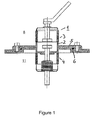
FIG. 1: shows a switch disconnector according to the invention.
FIG. 2: shows a switch disconnector according to the invention with direct function of a bushing.
FIG. 3: shows a bushing switch disconnector with a load-interrupter and circuit-breaker capability.
DETAILED DESCRIPTION OF THE INVENTION
The grounding position requires a connection, integrated in the bushing, from a “ground point” to the metallic center part 2 of the vacuum switching chamber 1, which is located between the isolating ceramics 3, 4 shown in FIG. 1.
In the situation shown in FIG. 1, in the same way as in the situation shown in FIG. 2, in which the three-position vacuum switching chamber is itself used directly as the bushing, an edge board 5 is fitted to the metallic center part 2 of the three-position vacuum switching chamber, and allows the connection to the “ground point”. The edge board 5 can also be equipped with a seal 6, which provides the seal to the gas area.
This can most expediently be achieved by the electrical ground connection forming a unit with the mechanical connection, so that the ground connection is ensured by the fitting of the bushing.
The described arrangement of the disconnector bushing can be used both for single-busbar and for double-busbar applications.
The three-position vacuum switching chamber in the form of a bushing disconnector can be designed as follows, based on even greater function integration.
FIG. 3 shows a corresponding bushing switch disconnector with, in addition to the functions of a connected position, disconnected position and grounding position, can also carry out the function of load switching and power switching, that is to say it additionally has a load switching and power switching capability.
For this purpose, a vacuum switching chamber is used which, as illustrated in FIG. 3, has a second area 10 or at least one shielded area within a vacuum switching chamber, which can also be arranged separately on the vacuum switching chamber, in which this switching path is located.
This makes it possible to ensure that, in practice, no plasma can pass from this switching path into the area of the grounding path during the disconnection of load currents or short-circuit currents.
This reduces vaporization of the isolation paths, or prevents it entirely when using a separate area, thus providing safe isolation in the mid-position. This is achieved by disconnection of both paths by means of a bellows or by means of a labyrinth composed of interleaved shielding components.
A contact system can be located in the load-interrupter switching area, formed from blade contacts. The features of a circuit-breaker vacuum switching chamber are required for a short-circuit-current disconnection capability. Both RMF and AMF contact systems may be used for this purpose.
RMF is short for radial magnetic field, and AMF for axial magnetic field.
In contrast to three-position vacuum switching chambers without a disconnection capability, this switching chamber with a disconnection capability requires a drive which quickly separates the switching contact pieces in a known manner, at least during disconnection of them, at least as far as the region of the disconnected position (mid-position).

Claims (4)

The invention claimed is:
1. A medium-voltage switchgear assembly comprising:
an enclosure filled with an insulating gas; and
a bushing extending through the enclosure such that an interior portion of the bushing is disposed inside the enclosure with the insulating gas and an exterior portion of the bushing is disposed outside the enclosure, the bushing comprising a vacuum switching chamber and a conductive edge board connected to and extending radially outward from the switching chamber, the edge board being connected to a wall of the enclosure and having a seal that engages an outer surface of the wall to form a gas tight seal therewith, the connection of the edge board to the wall forming a ground point for the switching chamber.
2. The medium-voltage switchgear assembly of claim 1, wherein the bushing has a cast-resin body that encapsulates the switching chamber.
3. The medium-voltage switchgear assembly of claim 2, wherein the switching chamber comprises a three-position switch enclosed in a vacuum insulated housing having a metal center portion disposed between ceramic end portions, the center portion being connected to the edge board.
4. The medium-voltage switchgear assembly of claim 3, wherein the switch comprises a moving contact and a fixed contact, the fixed contact being disposed in the interior portion of the bushing.
US10/583,216 2003-12-19 2004-12-20 Medium-voltage switchgear assembly Expired - Fee Related US8937262B2 (en)

Applications Claiming Priority (4)

Application Number Priority Date Filing Date Title
DE10360633.5 2003-12-19
DE10360633 2003-12-19
DE2003160633 DE10360633A1 (en) 2003-12-19 2003-12-19 Medium-voltage switchgear
PCT/EP2004/014480 WO2005062328A1 (en) 2003-12-19 2004-12-20 Medium voltage switchgear assembly

Publications (2)

Publication Number Publication Date
US20070145015A1 US20070145015A1 (en) 2007-06-28
US8937262B2 true US8937262B2 (en) 2015-01-20

Family

ID=34706436

Family Applications (1)

Application Number Title Priority Date Filing Date
US10/583,216 Expired - Fee Related US8937262B2 (en) 2003-12-19 2004-12-20 Medium-voltage switchgear assembly

Country Status (5)

Country Link
US (1) US8937262B2 (en)
EP (1) EP1697954A1 (en)
CN (1) CN1914704B (en)
DE (2) DE20321748U1 (en)
WO (1) WO2005062328A1 (en)

Cited By (1)

* Cited by examiner, † Cited by third party
Publication number Priority date Publication date Assignee Title
US11862944B1 (en) 2022-06-17 2024-01-02 Jst Power Equipment, Inc. Switchgear device with grounding device and related methods

Families Citing this family (11)

* Cited by examiner, † Cited by third party
Publication number Priority date Publication date Assignee Title
DE102006017131A1 (en) * 2006-04-12 2007-10-18 Areva Energietechnik Gmbh Three-position switch, in particular for a medium or high-voltage switchgear
FR2925755B1 (en) * 2007-12-21 2012-08-03 Schneider Electric Ind Sas INSULATION OF VACUUM BULB TYPE CUTTING DEVICE BY OVERMOLDING
FR2927194B1 (en) * 2008-01-31 2010-02-19 Schneider Electric Ind Sas VACUUM BULB FOR ELECTRICAL CUTTING APPARATUS PROVIDING AT LEAST DISCONNECT FUNCTION
DE102008023502B4 (en) * 2008-05-13 2010-06-17 Siemens Aktiengesellschaft Vacuum interrupter
JP5235620B2 (en) * 2008-11-14 2013-07-10 株式会社日立製作所 Vacuum switchgear
CN101807488A (en) * 2010-04-21 2010-08-18 山东晨鸿电气有限公司 Three-position device of vacuum interrupter
DE102010053466A1 (en) * 2010-11-30 2012-05-31 Maschinenfabrik Reinhausen Gmbh Step switch and vacuum interrupter for such a tap changer
CN102881510B (en) * 2012-09-24 2015-02-25 中国西电电气股份有限公司 Three-station vacuum arc extinguishing chamber
US10218161B2 (en) * 2014-02-25 2019-02-26 Abb Schweiz Ag Integrated compact bushing structure combining the functionality of primary contact with a current transformer primary conductor and a post insulator
CN105304400B (en) * 2015-11-02 2018-10-02 宁波耐吉新星自动化设备有限公司 Vacuum interrupter for solid insulation ring main unit
FR3070533B1 (en) * 2017-08-28 2019-09-13 Schneider Electric Industries Sas POLE OF CURRENT CUT

Citations (4)

* Cited by examiner, † Cited by third party
Publication number Priority date Publication date Assignee Title
US3812314A (en) * 1971-08-23 1974-05-21 Gen Electric High power electrical bushing having a vacuum switch encapsulated therein
US4618749A (en) * 1984-09-24 1986-10-21 Veb Otto Buchwitz Starkstrom Anlagebau Dresden Solid insulator-type vacuum switch gear
US6373015B1 (en) * 2000-01-03 2002-04-16 Eaton Corporation Integral load connector module
US20030094438A1 (en) * 2000-06-23 2003-05-22 Roman Renz Vacuum interrupter with two contact systems

Family Cites Families (6)

* Cited by examiner, † Cited by third party
Publication number Priority date Publication date Assignee Title
DE2037234A1 (en) * 1970-07-01 1972-02-03 Inst Prueffled Fuer Elektrisch Switching device for high voltages
DE2742775A1 (en) * 1977-09-20 1979-03-29 Siemens Ag Earthing switches in series with underground cables - operate with remote control of switches and associated vacuum interrupters incorporated in run of cable
DE3528770A1 (en) * 1985-08-10 1987-02-19 Driescher Eltech Werk Medium-voltage switching installation
DE4401356A1 (en) * 1994-01-14 1995-07-20 Siemens Ag Vacuum switching tube with special current terminal
JP3164033B2 (en) * 1997-10-03 2001-05-08 株式会社日立製作所 Busbar connection structure and insulating cover
JP2001222935A (en) * 2000-02-08 2001-08-17 Toshiba Corp Vacuum breaker

Patent Citations (5)

* Cited by examiner, † Cited by third party
Publication number Priority date Publication date Assignee Title
US3812314A (en) * 1971-08-23 1974-05-21 Gen Electric High power electrical bushing having a vacuum switch encapsulated therein
US4618749A (en) * 1984-09-24 1986-10-21 Veb Otto Buchwitz Starkstrom Anlagebau Dresden Solid insulator-type vacuum switch gear
US6373015B1 (en) * 2000-01-03 2002-04-16 Eaton Corporation Integral load connector module
US20030094438A1 (en) * 2000-06-23 2003-05-22 Roman Renz Vacuum interrupter with two contact systems
US6720515B2 (en) * 2000-06-23 2004-04-13 Siemens Aktiengesellschaft Vacuum interrupter with two contact systems

Cited By (1)

* Cited by examiner, † Cited by third party
Publication number Priority date Publication date Assignee Title
US11862944B1 (en) 2022-06-17 2024-01-02 Jst Power Equipment, Inc. Switchgear device with grounding device and related methods

Also Published As

Publication number Publication date
US20070145015A1 (en) 2007-06-28
DE10360633A1 (en) 2005-07-28
CN1914704B (en) 2011-09-21
EP1697954A1 (en) 2006-09-06
CN1914704A (en) 2007-02-14
DE20321748U1 (en) 2009-05-14
WO2005062328A1 (en) 2005-07-07

Similar Documents

Publication Publication Date Title
JP4162664B2 (en) Vacuum switchgear
US7829814B2 (en) Vacuum circuit interrupter grounding assembly
US6720515B2 (en) Vacuum interrupter with two contact systems
EP2546850B1 (en) Switchgear and method for operating switchgear
US5578805A (en) Metal-enclosed gas-filled switchgear units
US8937262B2 (en) Medium-voltage switchgear assembly
CA2612730C (en) Vacuum bulb for an electrical protection apparatus, such as a switch or a circuit breaker
US20080245772A1 (en) Vacuum Interrupter
KR20100020425A (en) Vacuum switch gear
US11005240B2 (en) Three phase switchgear or control gear
JP3577247B2 (en) Switchgear
US20220216021A1 (en) Circuit breaker
US5578804A (en) Metal-enclosed gas-insulated switching installation
JP2002159109A (en) Gas isolation switching device
US4700270A (en) Metal-encapsulated gas-insulated switching system
CA1265605A (en) Metalclad substation subdivided into tight compartments
AU2011273744A1 (en) Pressurised gas-insulated multi-phase control panel
KR100374239B1 (en) Switch gear
EP1748455A1 (en) Electrical switchgear
US20110096468A1 (en) Medium-voltage switchgear
JP2003308767A (en) Vacuum switch
JP2002329443A (en) Switchgear
JP2000285774A (en) Switchgear
US9742162B2 (en) Gas-insulated medium-voltage switchgear assembly
JPS60249219A (en) Vacuum breaker

Legal Events

Date Code Title Description
AS Assignment

Owner name: ABB TECHNOLOGY AG, SWITZERLAND

Free format text: ASSIGNMENT OF ASSIGNORS INTEREST;ASSIGNORS:FINK, HARALD;GENTSCH, DIETMAR;HYRENBACH, MAIK;REEL/FRAME:020329/0455;SIGNING DATES FROM 20071114 TO 20071125

Owner name: ABB TECHNOLOGY AG, SWITZERLAND

Free format text: ASSIGNMENT OF ASSIGNORS INTEREST;ASSIGNORS:FINK, HARALD;GENTSCH, DIETMAR;HYRENBACH, MAIK;SIGNING DATES FROM 20071114 TO 20071125;REEL/FRAME:020329/0455

FEPP Fee payment procedure

Free format text: PAYOR NUMBER ASSIGNED (ORIGINAL EVENT CODE: ASPN); ENTITY STATUS OF PATENT OWNER: LARGE ENTITY

FEPP Fee payment procedure

Free format text: MAINTENANCE FEE REMINDER MAILED (ORIGINAL EVENT CODE: REM.); ENTITY STATUS OF PATENT OWNER: LARGE ENTITY

LAPS Lapse for failure to pay maintenance fees

Free format text: PATENT EXPIRED FOR FAILURE TO PAY MAINTENANCE FEES (ORIGINAL EVENT CODE: EXP.); ENTITY STATUS OF PATENT OWNER: LARGE ENTITY

STCH Information on status: patent discontinuation

Free format text: PATENT EXPIRED DUE TO NONPAYMENT OF MAINTENANCE FEES UNDER 37 CFR 1.362

FP Lapsed due to failure to pay maintenance fee

Effective date: 20190120