US89340A - peters - Google Patents
peters Download PDFInfo
- Publication number
- US89340A US89340A US89340DA US89340A US 89340 A US89340 A US 89340A US 89340D A US89340D A US 89340DA US 89340 A US89340 A US 89340A
- Authority
- US
- United States
- Prior art keywords
- stove
- tanks
- water
- chamber
- pyle
- Prior art date
- Legal status (The legal status is an assumption and is not a legal conclusion. Google has not performed a legal analysis and makes no representation as to the accuracy of the status listed.)
- Expired - Lifetime
Links
- XLYOFNOQVPJJNP-UHFFFAOYSA-N water Substances O XLYOFNOQVPJJNP-UHFFFAOYSA-N 0.000 description 4
- 230000005855 radiation Effects 0.000 description 2
- 241000499489 Castor canadensis Species 0.000 description 1
- 235000011779 Menyanthes trifoliata Nutrition 0.000 description 1
- 230000009286 beneficial effect Effects 0.000 description 1
- 238000010276 construction Methods 0.000 description 1
- 238000001816 cooling Methods 0.000 description 1
- 238000004880 explosion Methods 0.000 description 1
- 238000010438 heat treatment Methods 0.000 description 1
- 230000000284 resting effect Effects 0.000 description 1
Images
Classifications
-
- A—HUMAN NECESSITIES
- A62—LIFE-SAVING; FIRE-FIGHTING
- A62C—FIRE-FIGHTING
- A62C37/00—Control of fire-fighting equipment
- A62C37/08—Control of fire-fighting equipment comprising an outlet device containing a sensor, or itself being the sensor, i.e. self-contained sprinklers
- A62C37/10—Releasing means, e.g. electrically released
Definitions
- Figure 2 a longitudinal vertical section thereof.
- Myimprovement consists in providing the stove with water-tanks, or reservoirs, which may empty their contents into the fire-chamber when it is upset, thus extinguishing the fire, and cooling the stove.
- a set of water-tanks, or reservoirs A A resting on a. projecting ledge, formed by the bottom of the stove.
- each tank communicates, near the upper end, with the interior of the stove, by orifices D D
- each tank may be provided with an opening in its top, through which to pour the water, said opening being closed by a cover, H. This opening also serves as an outlet for the escape of vapor arising from the partially-heated water, and renders explosions impossible.
- Air-spaces, or passages G O are formed between the tanks and the stove in the manner shown, so as to interfere with the radiation of heat from the surface of the stove as little as possible, and also to prevent the water from becoming too highly heated.
- These spaces may be simple openings between the stove and the tanks, or they may be'enclosed with perforated plates, in the form of registers. Both of these plans are shown in the drawings.
- the tanks are kept nearly full of water, and should the stove be overturnedamaybe drawnoff ,by the spigotsnF F, at the, bottom of the tanks, whenever desired.
- the tanks do not interfere with the radiation of heat from the stove to any considerable extent, and, in connection with the stove, possess all the advantages, and produce all the beneficial efl'ects of a moist warm-air furnace, and are well suited to the confined atmosphere of a railway-car.
- the projecting edge of the top plate .of the stove serves as a cover for the upper tier.
- the tiers or sets may be alike, except that thetanks in the up-- per tier are smaller than those in the lower, and double in number, less one, which is omitted, to make room for a stove-door.
Landscapes
- Health & Medical Sciences (AREA)
- Public Health (AREA)
- Business, Economics & Management (AREA)
- Emergency Management (AREA)
- Cookers (AREA)
Description
2 Sheets--Sheet 1. A. J. PYLE.
Car Heater.
Patented April 27, 1869.
Inventor.
I witness's s pM Mw Car Heater.
Patented April 27,1869.
o o a R Witnesses: Inventor:
A. J. PYLE, OF NEW GALILEE, PENNSYLVANIA.
Letters Patent No: 89,340, dated April 27, 1869.
SAFETY-STOVE FOR RAILROAD-CARS.
The Schedule referred to in these Letters Patent and making pan: of the aims.
To all whom it may concern Be it known that I, Dr. A. J. PYLE, of New Galilee, in the county of Beaver, and State of Pennsylvania, have invented an Improvement in Heating-Stoves for Railway-Oars; and I do hereby declare that the following is a full and exact description thereof, reference being had to the accompanying drawings, making part of this specification- Figure 1 being a perspive view of the same, partly broken away to show the interior.
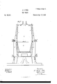
Figure 2, a longitudinal vertical section thereof.
, Like letters designatecOrresponding parts in..hnth figures.
Myimprovement consists in providing the stove with water-tanks, or reservoirs, which may empty their contents into the fire-chamber when it is upset, thus extinguishing the fire, and cooling the stove.
This feature renders my invention peculiarly applicable, notonlyto stoves used for heating railway-cars, but in other situations where the stove is liable to be accidentally overturned.
Let B represent the fire-chamber, and
E, the radiating chamber of a stove, of any desired external form.
Around the exterior of the fire-chamber B is arranged a set of water-tanks, or reservoirs A A, resting on a. projecting ledge, formed by the bottom of the stove.
The interior of each tank communicates, near the upper end, with the interior of the stove, by orifices D D And each tank may be provided with an opening in its top, through which to pour the water, said opening being closed by a cover, H. This opening also serves as an outlet for the escape of vapor arising from the partially-heated water, and renders explosions impossible.
Air-spaces, or passages G O are formed between the tanks and the stove in the manner shown, so as to interfere with the radiation of heat from the surface of the stove as little as possible, and also to prevent the water from becoming too highly heated. These spaces may be simple openings between the stove and the tanks, or they may be'enclosed with perforated plates, in the form of registers. Both of these plans are shown in the drawings.
When the stove is in use, the tanks are kept nearly full of water, and should the stove be overturnedamaybe drawnoff ,by the spigotsnF F, at the, bottom of the tanks, whenever desired.
The tanks do not interfere with the radiation of heat from the stove to any considerable extent, and, in connection with the stove, possess all the advantages, and produce all the beneficial efl'ects of a moist warm-air furnace, and are well suited to the confined atmosphere of a railway-car.
I have thus far described but one set of tanks, andwithout special reference to their arrangement; but I have shown in the drawings a second tier of tanks, or reservoirs, arranged around the upper part, or radiating chamber of the stove, above the first set. The projecting edge of the top plate .of the stove serves as a cover for the upper tier. In other respects the tiers or sets may be alike, except that thetanks in the up-- per tier are smaller than those in the lower, and double in number, less one, which is omitted, to make room for a stove-door.
The construction of the stove in two parts, as shown, with upper and lower tanks, is a good and desirable one.
DR. A. J. PYLE.
Witnesses J. J. ANDERSON, J. A. Serums.
Publications (1)
| Publication Number | Publication Date |
|---|---|
| US89340A true US89340A (en) | 1869-04-27 |
Family
ID=2158822
Family Applications (1)
| Application Number | Title | Priority Date | Filing Date |
|---|---|---|---|
| US89340D Expired - Lifetime US89340A (en) | peters |
Country Status (1)
| Country | Link |
|---|---|
| US (1) | US89340A (en) |
-
0
- US US89340D patent/US89340A/en not_active Expired - Lifetime
Similar Documents
| Publication | Publication Date | Title |
|---|---|---|
| US34871A (en) | Improvement in cooking-stoves | |
| US89340A (en) | peters | |
| US660357A (en) | Heating-stove. | |
| US90331A (en) | corse | |
| US141821A (en) | Improvement | |
| US102462A (en) | Improvement in cooking-stoves | |
| US103510A (en) | sexton | |
| US94026A (en) | Improvement in portable heating-attachment for stoves | |
| US68366A (en) | peters | |
| US81892A (en) | To all whom it may concern | |
| US76292A (en) | Improvement in cooking-stove tanks | |
| US89693A (en) | Watson sanford | |
| USRE5442E (en) | Improvement in reservoir cooking-stoves | |
| US56525A (en) | Improvement in cooking-stoves | |
| US30301A (en) | Sto ve-kadiatob | |
| US96429A (en) | hbrmance | |
| US142080A (en) | Improvement in reservoir cooking-stoves | |
| US86255A (en) | Cyrus smith | |
| US95725A (en) | And drying-stove | |
| US342232A (en) | sqmeryille | |
| USRE4530E (en) | Improvement in cooking-stoves | |
| US58811A (en) | Radiating stove and drum | |
| US204939A (en) | Improvement in furnaces | |
| US95026A (en) | kline | |
| US38423A (en) | Improvement in cooking-stoves |