US8933773B2 - Laminated layer structure for producing an insulation material - Google Patents
Laminated layer structure for producing an insulation material Download PDFInfo
- Publication number
- US8933773B2 US8933773B2 US13/849,741 US201313849741A US8933773B2 US 8933773 B2 US8933773 B2 US 8933773B2 US 201313849741 A US201313849741 A US 201313849741A US 8933773 B2 US8933773 B2 US 8933773B2
- Authority
- US
- United States
- Prior art keywords
- layer
- glass fabric
- stage resin
- layer structure
- laminated
- Prior art date
- Legal status (The legal status is an assumption and is not a legal conclusion. Google has not performed a legal analysis and makes no representation as to the accuracy of the status listed.)
- Active
Links
- 239000012774 insulation material Substances 0.000 title claims abstract description 17
- 239000010410 layer Substances 0.000 claims abstract description 135
- 229920005989 resin Polymers 0.000 claims abstract description 68
- 239000011347 resin Substances 0.000 claims abstract description 68
- 239000004744 fabric Substances 0.000 claims abstract description 49
- 239000011521 glass Substances 0.000 claims abstract description 49
- 238000004804 winding Methods 0.000 claims abstract description 47
- 239000012792 core layer Substances 0.000 claims abstract description 19
- 229920000728 polyester Polymers 0.000 claims description 29
- 239000011888 foil Substances 0.000 claims description 27
- 238000010438 heat treatment Methods 0.000 claims description 14
- 238000004519 manufacturing process Methods 0.000 claims description 9
- IISBACLAFKSPIT-UHFFFAOYSA-N bisphenol A Chemical compound C=1C=C(O)C=CC=1C(C)(C)C1=CC=C(O)C=C1 IISBACLAFKSPIT-UHFFFAOYSA-N 0.000 claims description 6
- 238000000926 separation method Methods 0.000 claims description 5
- 239000004593 Epoxy Substances 0.000 claims description 3
- 238000009413 insulation Methods 0.000 abstract description 14
- 230000004888 barrier function Effects 0.000 abstract description 8
- 229920006267 polyester film Polymers 0.000 abstract 1
- 238000006116 polymerization reaction Methods 0.000 description 8
- 238000003475 lamination Methods 0.000 description 6
- 239000000463 material Substances 0.000 description 6
- 238000000034 method Methods 0.000 description 6
- 239000002131 composite material Substances 0.000 description 5
- 239000007788 liquid Substances 0.000 description 4
- 239000013067 intermediate product Substances 0.000 description 3
- 239000010754 BS 2869 Class F Substances 0.000 description 2
- 239000002390 adhesive tape Substances 0.000 description 2
- 239000011248 coating agent Substances 0.000 description 2
- 238000000576 coating method Methods 0.000 description 2
- 238000001816 cooling Methods 0.000 description 2
- 239000003822 epoxy resin Substances 0.000 description 2
- 238000010030 laminating Methods 0.000 description 2
- 238000002844 melting Methods 0.000 description 2
- 230000008018 melting Effects 0.000 description 2
- 229920003055 poly(ester-imide) Polymers 0.000 description 2
- 229920000647 polyepoxide Polymers 0.000 description 2
- 239000007787 solid Substances 0.000 description 2
- 230000015572 biosynthetic process Effects 0.000 description 1
- 230000015556 catabolic process Effects 0.000 description 1
- 238000006243 chemical reaction Methods 0.000 description 1
- 239000004020 conductor Substances 0.000 description 1
- 238000005520 cutting process Methods 0.000 description 1
- 238000001035 drying Methods 0.000 description 1
- 230000000977 initiatory effect Effects 0.000 description 1
- 230000010354 integration Effects 0.000 description 1
- 239000002243 precursor Substances 0.000 description 1
- 239000000047 product Substances 0.000 description 1
Images

Classifications
-
- H—ELECTRICITY
- H01—ELECTRIC ELEMENTS
- H01F—MAGNETS; INDUCTANCES; TRANSFORMERS; SELECTION OF MATERIALS FOR THEIR MAGNETIC PROPERTIES
- H01F3/00—Cores, Yokes, or armatures
- H01F3/02—Cores, Yokes, or armatures made from sheets
-
- B—PERFORMING OPERATIONS; TRANSPORTING
- B32—LAYERED PRODUCTS
- B32B—LAYERED PRODUCTS, i.e. PRODUCTS BUILT-UP OF STRATA OF FLAT OR NON-FLAT, e.g. CELLULAR OR HONEYCOMB, FORM
- B32B1/00—Layered products having a non-planar shape
- B32B1/08—Tubular products
-
- B—PERFORMING OPERATIONS; TRANSPORTING
- B32—LAYERED PRODUCTS
- B32B—LAYERED PRODUCTS, i.e. PRODUCTS BUILT-UP OF STRATA OF FLAT OR NON-FLAT, e.g. CELLULAR OR HONEYCOMB, FORM
- B32B17/00—Layered products essentially comprising sheet glass, or glass, slag, or like fibres
- B32B17/02—Layered products essentially comprising sheet glass, or glass, slag, or like fibres in the form of fibres or filaments
- B32B17/04—Layered products essentially comprising sheet glass, or glass, slag, or like fibres in the form of fibres or filaments bonded with or embedded in a plastic substance
-
- B—PERFORMING OPERATIONS; TRANSPORTING
- B32—LAYERED PRODUCTS
- B32B—LAYERED PRODUCTS, i.e. PRODUCTS BUILT-UP OF STRATA OF FLAT OR NON-FLAT, e.g. CELLULAR OR HONEYCOMB, FORM
- B32B27/00—Layered products comprising a layer of synthetic resin
- B32B27/06—Layered products comprising a layer of synthetic resin as the main or only constituent of a layer, which is next to another layer of the same or of a different material
- B32B27/08—Layered products comprising a layer of synthetic resin as the main or only constituent of a layer, which is next to another layer of the same or of a different material of synthetic resin
-
- B—PERFORMING OPERATIONS; TRANSPORTING
- B32—LAYERED PRODUCTS
- B32B—LAYERED PRODUCTS, i.e. PRODUCTS BUILT-UP OF STRATA OF FLAT OR NON-FLAT, e.g. CELLULAR OR HONEYCOMB, FORM
- B32B27/00—Layered products comprising a layer of synthetic resin
- B32B27/12—Layered products comprising a layer of synthetic resin next to a fibrous or filamentary layer
-
- B—PERFORMING OPERATIONS; TRANSPORTING
- B32—LAYERED PRODUCTS
- B32B—LAYERED PRODUCTS, i.e. PRODUCTS BUILT-UP OF STRATA OF FLAT OR NON-FLAT, e.g. CELLULAR OR HONEYCOMB, FORM
- B32B27/00—Layered products comprising a layer of synthetic resin
- B32B27/36—Layered products comprising a layer of synthetic resin comprising polyesters
-
- B—PERFORMING OPERATIONS; TRANSPORTING
- B32—LAYERED PRODUCTS
- B32B—LAYERED PRODUCTS, i.e. PRODUCTS BUILT-UP OF STRATA OF FLAT OR NON-FLAT, e.g. CELLULAR OR HONEYCOMB, FORM
- B32B27/00—Layered products comprising a layer of synthetic resin
- B32B27/38—Layered products comprising a layer of synthetic resin comprising epoxy resins
-
- B—PERFORMING OPERATIONS; TRANSPORTING
- B32—LAYERED PRODUCTS
- B32B—LAYERED PRODUCTS, i.e. PRODUCTS BUILT-UP OF STRATA OF FLAT OR NON-FLAT, e.g. CELLULAR OR HONEYCOMB, FORM
- B32B27/00—Layered products comprising a layer of synthetic resin
- B32B27/42—Layered products comprising a layer of synthetic resin comprising condensation resins of aldehydes, e.g. with phenols, ureas or melamines
-
- H—ELECTRICITY
- H01—ELECTRIC ELEMENTS
- H01B—CABLES; CONDUCTORS; INSULATORS; SELECTION OF MATERIALS FOR THEIR CONDUCTIVE, INSULATING OR DIELECTRIC PROPERTIES
- H01B3/00—Insulators or insulating bodies characterised by the insulating materials; Selection of materials for their insulating or dielectric properties
- H01B3/18—Insulators or insulating bodies characterised by the insulating materials; Selection of materials for their insulating or dielectric properties mainly consisting of organic substances
- H01B3/30—Insulators or insulating bodies characterised by the insulating materials; Selection of materials for their insulating or dielectric properties mainly consisting of organic substances plastics; resins; waxes
- H01B3/40—Insulators or insulating bodies characterised by the insulating materials; Selection of materials for their insulating or dielectric properties mainly consisting of organic substances plastics; resins; waxes epoxy resins
-
- H—ELECTRICITY
- H01—ELECTRIC ELEMENTS
- H01B—CABLES; CONDUCTORS; INSULATORS; SELECTION OF MATERIALS FOR THEIR CONDUCTIVE, INSULATING OR DIELECTRIC PROPERTIES
- H01B3/00—Insulators or insulating bodies characterised by the insulating materials; Selection of materials for their insulating or dielectric properties
- H01B3/18—Insulators or insulating bodies characterised by the insulating materials; Selection of materials for their insulating or dielectric properties mainly consisting of organic substances
- H01B3/30—Insulators or insulating bodies characterised by the insulating materials; Selection of materials for their insulating or dielectric properties mainly consisting of organic substances plastics; resins; waxes
- H01B3/47—Insulators or insulating bodies characterised by the insulating materials; Selection of materials for their insulating or dielectric properties mainly consisting of organic substances plastics; resins; waxes fibre-reinforced plastics, e.g. glass-reinforced plastics
-
- B—PERFORMING OPERATIONS; TRANSPORTING
- B32—LAYERED PRODUCTS
- B32B—LAYERED PRODUCTS, i.e. PRODUCTS BUILT-UP OF STRATA OF FLAT OR NON-FLAT, e.g. CELLULAR OR HONEYCOMB, FORM
- B32B2262/00—Composition or structural features of fibres which form a fibrous or filamentary layer or are present as additives
- B32B2262/10—Inorganic fibres
- B32B2262/101—Glass fibres
-
- B—PERFORMING OPERATIONS; TRANSPORTING
- B32—LAYERED PRODUCTS
- B32B—LAYERED PRODUCTS, i.e. PRODUCTS BUILT-UP OF STRATA OF FLAT OR NON-FLAT, e.g. CELLULAR OR HONEYCOMB, FORM
- B32B2307/00—Properties of the layers or laminate
- B32B2307/20—Properties of the layers or laminate having particular electrical or magnetic properties, e.g. piezoelectric
- B32B2307/206—Insulating
-
- B—PERFORMING OPERATIONS; TRANSPORTING
- B32—LAYERED PRODUCTS
- B32B—LAYERED PRODUCTS, i.e. PRODUCTS BUILT-UP OF STRATA OF FLAT OR NON-FLAT, e.g. CELLULAR OR HONEYCOMB, FORM
- B32B2307/00—Properties of the layers or laminate
- B32B2307/30—Properties of the layers or laminate having particular thermal properties
- B32B2307/306—Resistant to heat
- B32B2307/3065—Flame resistant or retardant, fire resistant or retardant
-
- B—PERFORMING OPERATIONS; TRANSPORTING
- B32—LAYERED PRODUCTS
- B32B—LAYERED PRODUCTS, i.e. PRODUCTS BUILT-UP OF STRATA OF FLAT OR NON-FLAT, e.g. CELLULAR OR HONEYCOMB, FORM
- B32B2307/00—Properties of the layers or laminate
- B32B2307/50—Properties of the layers or laminate having particular mechanical properties
-
- B—PERFORMING OPERATIONS; TRANSPORTING
- B32—LAYERED PRODUCTS
- B32B—LAYERED PRODUCTS, i.e. PRODUCTS BUILT-UP OF STRATA OF FLAT OR NON-FLAT, e.g. CELLULAR OR HONEYCOMB, FORM
- B32B2597/00—Tubular articles, e.g. hoses, pipes
-
- Y—GENERAL TAGGING OF NEW TECHNOLOGICAL DEVELOPMENTS; GENERAL TAGGING OF CROSS-SECTIONAL TECHNOLOGIES SPANNING OVER SEVERAL SECTIONS OF THE IPC; TECHNICAL SUBJECTS COVERED BY FORMER USPC CROSS-REFERENCE ART COLLECTIONS [XRACs] AND DIGESTS
- Y10—TECHNICAL SUBJECTS COVERED BY FORMER USPC
- Y10T—TECHNICAL SUBJECTS COVERED BY FORMER US CLASSIFICATION
- Y10T428/00—Stock material or miscellaneous articles
- Y10T428/13—Hollow or container type article [e.g., tube, vase, etc.]
- Y10T428/131—Glass, ceramic, or sintered, fused, fired, or calcined metal oxide or metal carbide containing [e.g., porcelain, brick, cement, etc.]
- Y10T428/1314—Contains fabric, fiber particle, or filament made of glass, ceramic, or sintered, fused, fired, or calcined metal oxide, or metal carbide or other inorganic compound [e.g., fiber glass, mineral fiber, sand, etc.]
-
- Y—GENERAL TAGGING OF NEW TECHNOLOGICAL DEVELOPMENTS; GENERAL TAGGING OF CROSS-SECTIONAL TECHNOLOGIES SPANNING OVER SEVERAL SECTIONS OF THE IPC; TECHNICAL SUBJECTS COVERED BY FORMER USPC CROSS-REFERENCE ART COLLECTIONS [XRACs] AND DIGESTS
- Y10—TECHNICAL SUBJECTS COVERED BY FORMER USPC
- Y10T—TECHNICAL SUBJECTS COVERED BY FORMER US CLASSIFICATION
- Y10T428/00—Stock material or miscellaneous articles
- Y10T428/24—Structurally defined web or sheet [e.g., overall dimension, etc.]
- Y10T428/24802—Discontinuous or differential coating, impregnation or bond [e.g., artwork, printing, retouched photograph, etc.]
- Y10T428/24917—Discontinuous or differential coating, impregnation or bond [e.g., artwork, printing, retouched photograph, etc.] including metal layer
-
- Y—GENERAL TAGGING OF NEW TECHNOLOGICAL DEVELOPMENTS; GENERAL TAGGING OF CROSS-SECTIONAL TECHNOLOGIES SPANNING OVER SEVERAL SECTIONS OF THE IPC; TECHNICAL SUBJECTS COVERED BY FORMER USPC CROSS-REFERENCE ART COLLECTIONS [XRACs] AND DIGESTS
- Y10—TECHNICAL SUBJECTS COVERED BY FORMER USPC
- Y10T—TECHNICAL SUBJECTS COVERED BY FORMER US CLASSIFICATION
- Y10T428/00—Stock material or miscellaneous articles
- Y10T428/24—Structurally defined web or sheet [e.g., overall dimension, etc.]
- Y10T428/24942—Structurally defined web or sheet [e.g., overall dimension, etc.] including components having same physical characteristic in differing degree
- Y10T428/2495—Thickness [relative or absolute]
- Y10T428/24967—Absolute thicknesses specified
- Y10T428/24975—No layer or component greater than 5 mils thick
-
- Y—GENERAL TAGGING OF NEW TECHNOLOGICAL DEVELOPMENTS; GENERAL TAGGING OF CROSS-SECTIONAL TECHNOLOGIES SPANNING OVER SEVERAL SECTIONS OF THE IPC; TECHNICAL SUBJECTS COVERED BY FORMER USPC CROSS-REFERENCE ART COLLECTIONS [XRACs] AND DIGESTS
- Y10—TECHNICAL SUBJECTS COVERED BY FORMER USPC
- Y10T—TECHNICAL SUBJECTS COVERED BY FORMER US CLASSIFICATION
- Y10T428/00—Stock material or miscellaneous articles
- Y10T428/249921—Web or sheet containing structurally defined element or component
Definitions
- the disclosure relates to a laminated layer structure for the production of a sheet-like insulation material, and also to an insulation material produced therefrom.
- high-voltage-system components such as dry transformers
- insulation means For example, when there is little separation between two components operated at different voltage levels (for example, between an upper- and lower-voltage winding of a transformer), electrical breakdown can result. In order to prevent this, insulation barriers can be used which increase the flashover length and thus provide increased reliability of operation of the component.
- this type of barrier is designed as a thin-walled insulating hollow cylinder arranged within the radial region that separates the lower-voltage winding, which can be located radially inwards, from the upper-voltage winding, which can be located radially outwards.
- the cylinder can be composed, for example, of a thin-walled multilayer laminate.
- Laminate is the term used for a material or a product which is composed of two or more layers where large surfaces have been bonded to one another by adhesion or by other means. These layers can be composed of identical or different materials.
- a laminate suitable for the abovementioned insulation purpose can have, for example, the following layer structure, where the polyester foil can determine electrical strength:
- polyester foil adhesive-bonded from multiple plies for example, up to 4 plies
- the layer thickness in each case being 350 ⁇ m.
- This type of laminate, resembling a strip is produced in roll form by means of appropriate lamination equipment.
- a strip section of desired length and width is manually bent into a hollow cylinder shape and fixed at an overlap by a heat-resistant adhesive tape. It can be desirable that the entire structure has a heat resistance in temperature class F, i.e., 155° C., for application in dry transformers in the high-voltage sector.
- a disadvantage here is that the first-mentioned laminate structure with its overall thickness of about 1 mm can have restricted stability which is not suitable for the production of hollow insulation cylinders for relatively large transformers, for example, for a rated power of 5 MW and above. Addition of further layers with a resultant higher overall thickness involves increased cost and use of material, and can be disadvantageous. Another disadvantage is that this type of insulation barrier can contribute to a fire load of a transformer.
- the four-ply polyester foil described as an alternative has slightly higher mechanical stability, because of a lack of a coating on the external sides of the foil composite it may only be suitable for temperature class B, i.e., 130° C.
- a laminated layer structure for the production of an insulation material comprising, in the following sequence: a first B-stage resin layer; a first glass fabric layer; a core layer made of polyester foil; a second glass fabric layer; and a second B-stage resin layer.
- an insulation material is provided that is produced by heating an exemplary laminated layer structure to a baking temperature, wherein the heating is effective to completely polymerize the B-stage resin of the first and second B-stage resin layers.
- a high-voltage winding comprising: a lower-voltage winding that is arranged in the form of a hollow cylinder around a winding axis, an upper-voltage winding arranged in the form of a hollow cylinder around the same winding axis, wherein the upper-voltage winding is radially separated from the lower-voltage winding, and an exemplary laminated layer structure, wherein the laminated layer structure is present in a cavity formed by the radial separation between the lower-voltage winding and the upper-voltage winding.
- FIG. 1 shows an example of a first laminated layer structure, according to an exemplary aspect.
- FIG. 2 shows an example of a second laminated layer structure, according to an exemplary aspect.
- an insulation material and a suitable precursor therefore which features increased stability or reduced content of combustible materials.
- a laminated layer structure for the production of a sheet-like insulation material.
- the structure can be characterized by the following sequence of sheet-like individual layers arranged on top of one another:
- an underlying concept is to use, instead of an alternating sequence of polyester foil and polyester non-woven, a core layer made of polyester foil surrounded on both sides by a layer of glass fabric with an adjacent layer of B-stage resin.
- B-stage applied to a resin means, for example, that the process of hardening of the resin has begun but then has been intentionally interrupted in such a way that the resin is in a state of incomplete polymerization.
- the expression B-stage applied to a resin can also mean that this has been converted to a solid state by appropriate heating to a temperature of, for example, 80° C., that brings about melting and then cooling, without initiating the actual chemical reaction of polymerization.
- the resin in this type of state can be remelted at an appropriate temperature, while the actual polymerization takes place at a temperature above the temperature that brings about melting.
- the resin can be applied in the form of a liquid A-stage resin, for example, by means of a roll with appropriate surface structure.
- a drying process for example, it can then be passed through an oven where the temperature is such that although the resin is then converted to a B-stage resin, polymerization is substantially avoided.
- the lamination of a multilayer structure can comprise laminating a plurality of plies in a single lamination process.
- the lamination of a multilayer structure can also comprise merely laminating two layers to give an intermediate product which is wound up onto a roll. For example, the intermediate product can then be subsequently laminated together with further layers.
- a finished laminated layer structure does not yet have the desired final stability.
- the laminated layer structure may still have to be heated to a baking temperature so that the B-stage resin becomes liquid and bonds to the glass fabric layer.
- the B-stage resin can be, at least to some extent, absorbed into the interstices of the glass fabric layer.
- the baking temperature can be sufficiently high to initiate the polymerization process.
- the polymerization of the resin can be complete and can form an insulation material with appropriately high stability.
- the arrangement of the resulting glass fabric composite layers at the two external sides of the sheet-like insulation material can ensure that the overall structure has high stability, even at a low overall thickness.
- the content of combustible material in the laminate layer can be advantageously reduced because, in contrast to a polyester non-woven that in an exemplary embodiment is omitted, the glass fabric does not contribute to fire load.
- the ratio of the thickness of a resin layer to the thickness of a glass fabric layer adjacent thereto is about 3:20.
- the amount of the liquid resin can be adjusted so as to be appropriate to the volume of the space to be filled within the glass fabric.
- the thickness of each of the resin layers is about 15 ⁇ m and the thickness of each of the glass fabric layers is about 100 ⁇ m.
- the thickness achieved for the two outer layers, taking account of the abovementioned ratio, can be adjusted to be appropriate for an overall thickness of about 1 mm for the sheet-like insulation material.
- the exemplary thickness of the resin layers for example, 15 ⁇ m, can be a lower limit for giving adequate stability together with the respective glass fabric layer. Higher layer thicknesses, for example, 50 ⁇ m, can also be possible and useful. In this case, for example, the resin layer is not absorbed completely into the glass fabric and the surface is correspondingly smoother.
- the thickness of each resin layer can be from about 15 to 50 ⁇ m.
- a further increase in the thickness of the glass fabric layer can be useful in the event of an increased overall thickness, but even in this case does not contribute to fire load.
- an increased overall thickness can be employed, a further reduction in the thickness of the polyester foil can be made for reducing fire load, and compensation can be achieved by correspondingly increasing the thickness of the glass fabric layers.
- an increased overall thickness can be employed in view of the lower insulation capability of the glass fabric in comparison with the polyester foil.
- the core layer can have two plies of a polyester foil of a thickness of about 350 ⁇ m.
- a thickness of 350 ⁇ m can be a readily available thickness, while foils with increased thickness of, for example, 500 ⁇ m can be more difficult to produce.
- the insulation core can be manufactured from two plies of a foil of a thickness of 350 ⁇ m.
- the resultant overall thickness, together with the layer thicknesses of the two external plies, can approach 1 mm.
- the respective layer thicknesses can be scaled up appropriately and/or can be replicated by using an appropriately increased number of individual layers.
- this type of laminate structure can then be initially produced in the form of a layer structure of polyester foil, glass fabric and B-stage resin, where the polyester-foil sides of two plies of this intermediate product can then be adhesive-bonded or laminated to one another.
- phenol-epoxy precondensate or bisphenol A resin can be used as the B-stage resin. These can provide good results when used for coating, and they can also have suitable temperature-related properties. Examples can include Hexion Epenol 9968-LG as an exemplary phenol-epoxy precondensate and Albesiano 8045/A as an exemplary bisphenol A resin.
- the baked and hardened state provides heat resistance corresponding to temperature class F, i.e., above 155° C.
- it can be desirable that the baking temperature is not excessively above the heat-resistance temperature, for example, within the range from 120° C. to 180° C., for example, about 140° C.
- the laminated layer structure has a hollow cylindrical shape which has been adjusted to be appropriate to the internal space formed between lower- and upper-voltage windings in a transformer that is to be manufactured.
- a hollow cylindrical shape of this type can be provided by cutting a section of appropriate width and length of a laminate (for example, from a roll on which it is delivered). Clamps can be used to fix it in the appropriate shape. For example, to provide insulation of an appropriate overlap, a few centimeters can be provided here where the two ends are bonded.
- the diameter of the cylinder can be, for example, from 0.5 m to 2 m. The diameter can depend on the rated power of the transformer and on the structure of the winding.
- the structure before the laminated layer structure is used as insulation material, the structure can be heated to at least the baking temperature for a period in order to produce the final insulation material with the desired strength via formation of the outer glass fabric composite layers or complete polymerization of the resin.
- An exemplary temperature range for the period of heating can be from 120° C. to 180° C. for a period of at least 30 min.
- a high-voltage winding including: a lower-voltage winding, arranged in the form of a hollow cylinder around a winding axis; an upper-voltage winding, arranged in the form of a hollow cylinder around the same winding axis; wherein there is a radial separation between the lower-voltage winding and the upper-voltage winding.
- the high-voltage winding can include an exemplary laminated layer structure of an appropriately adapted shape arranged within a cavity formed in the radial separation.
- the laminated layer structure can be an insulation barrier between the lower- and upper-voltage winding. Because a winding of this type can be predominantly of a radially symmetrical structure, the shape of the intervening space between the two windings can be similar to a cylinder.
- a hollow cylindrical shape of the laminated layer structure can be a suitable shape for permitting easy integration into the entire winding. For example, it is also conceivable to assemble a hollow cylindrical shape of this type from a plurality of shell-like segments.
- the final electrical functionality of a winding of this type can be attained when it has been heated for a period of time, to at least a baking temperature such that a completely polymerized glass fabric composite material has been formed at the external sides of the hollow cylinder.
- This type of heating for a period of time can be an existing process step during the production process of a transformer.
- An example is when a B-stage resin, for example, a prepreg, is used for insulating the conductors in the lower-voltage winding. For example, there is no need for any additional heating procedure for the hollow cylinder used as insulation barrier.
- the use of a heat-resistant adhesive tape to fix the hollow cylinder can also be omitted because after the heating process, the resin, which initially is again liquid, can produce a bond for bonding the laminate, rolled into the shape of a cylinder. This can result in high strength after hardening.
- FIG. 1 shows an exemplary embodiment, not necessarily to scale, of a first laminated layer structure 10 including individual layers, wherein the reference numerals represent the following:
- the resin layers 12 , 20 can be absorbed at least to some extent into the cavities of the adjacent glass fabric layers 14 , 18 and, with such material, form a solid composite material resulting from the complete polymerization of the resin.
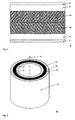
- FIG. 2 shows an exemplary embodiment of a second laminated layer structure 30 , which has a hollow cylindrical shape 32 arranged around a winding axis 44 .
- This depiction which is not necessarily to scale, shows a structure of the individual layers, wherein the reference numerals represent the following:
- the layer thicknesses mentioned are exemplary guideline values which are themselves subject to, for example, manufacturing tolerances.
Landscapes
- Physics & Mathematics (AREA)
- Spectroscopy & Molecular Physics (AREA)
- Engineering & Computer Science (AREA)
- Mechanical Engineering (AREA)
- Power Engineering (AREA)
- Laminated Bodies (AREA)
Abstract
Description
-
- 8 μm of hardened polyester imide resin or epoxy resin;
- 50 μm of polyester non-woven;
- 350 μm of polyester foil;
- 50 μm of polyester non-woven;
- 350 μm of polyester foil;
- 50 μm of polyester non-woven;
- 8 μm of hardened polyester imide resin or epoxy resin.
-
- B-stage resin;
- glass fabric;
- core layer made of polyester foil;
- glass fabric;
- B-stage resin.
- 12: 15 μm of a B-stage resin, for example Hexion Epenol 9968-LG
- 14: 100 μm of glass fabric
- 16 a: 350 μm of polyester foil, forming a first sublayer of the core layer
- 16 b: 350 μm of polyester foil, forming a second sublayer of the core layer
- 18: 100 μm of glass fabric
- 20: 15 μm of a B-stage resin, for example Hexion Epenol 9968-LG.
- 34: 15 μm of a B-stage resin, for example Albesiano 8045/A
- 36: 100 μm of glass fabric
- 38: 700 μm of core layer made of polyester foil
- 40: 100 μm of glass fabric
- 42: 15 μm of a B-stage resin, for example Albesiano 8045/A.
- 10 first example of a laminated layer structure
- 12 first individual layer of B-stage resin
- 14 first individual layer of glass fabric
- 16 a first polyester foil layer of core layer
- 16 b second polyester foil layer of core layer
- 18 second individual layer of glass fabric
- 20 second individual layer of B-stage resin
- 30 second example of a laminated layer structure
- 32 hollow cylindrical shape
- 34 first individual layer of B-stage resin
- 36 first individual layer of glass fabric
- 38 core layer
- 40 second individual layer of glass fabric
- 42 second individual layer of B-stage resin
- 44 winding axis
Claims (19)
Applications Claiming Priority (4)
| Application Number | Priority Date | Filing Date | Title |
|---|---|---|---|
| EP10178748.9 | 2010-09-23 | ||
| EP10178748.9A EP2434499B1 (en) | 2010-09-23 | 2010-09-23 | Laminated layer construction for producing an insulating material |
| EP10178748 | 2010-09-23 | ||
| PCT/EP2011/003755 WO2012037998A1 (en) | 2010-09-23 | 2011-07-27 | Laminated layer structure for producing an insulation material |
Related Parent Applications (1)
| Application Number | Title | Priority Date | Filing Date |
|---|---|---|---|
| PCT/EP2011/003755 Continuation WO2012037998A1 (en) | 2010-09-23 | 2011-07-27 | Laminated layer structure for producing an insulation material |
Publications (2)
| Publication Number | Publication Date |
|---|---|
| US20130214892A1 US20130214892A1 (en) | 2013-08-22 |
| US8933773B2 true US8933773B2 (en) | 2015-01-13 |
Family
ID=43799592
Family Applications (1)
| Application Number | Title | Priority Date | Filing Date |
|---|---|---|---|
| US13/849,741 Active US8933773B2 (en) | 2010-09-23 | 2013-03-25 | Laminated layer structure for producing an insulation material |
Country Status (4)
| Country | Link |
|---|---|
| US (1) | US8933773B2 (en) |
| EP (1) | EP2434499B1 (en) |
| CN (1) | CN103109328B (en) |
| WO (1) | WO2012037998A1 (en) |
Cited By (1)
| Publication number | Priority date | Publication date | Assignee | Title |
|---|---|---|---|---|
| US20170278620A1 (en) * | 2014-12-11 | 2017-09-28 | Ckd Corporation | Coil and coil production method |
Families Citing this family (1)
| Publication number | Priority date | Publication date | Assignee | Title |
|---|---|---|---|---|
| CN104369506B (en) * | 2014-11-19 | 2016-06-29 | 太仓弘杉环保科技有限公司 | A kind of insulating trip for biochemical pharmacy equipment |
Citations (10)
| Publication number | Priority date | Publication date | Assignee | Title |
|---|---|---|---|---|
| DE2323923A1 (en) | 1972-09-21 | 1974-04-04 | Sprecher & Schuh Ag | Plastics housing for power switch - is of multilayer type with outer layers shrunk on |
| US3843481A (en) | 1971-10-21 | 1974-10-22 | Kalle Ag | Plastic laminate |
| US4289172A (en) * | 1978-05-31 | 1981-09-15 | Ekstroem Stig Ove Mauritz | Reinforced bitumen pipes and process for their manufacture |
| US4675235A (en) * | 1986-01-09 | 1987-06-23 | Corning Glass Works | Laminated synthetic mica articles |
| DE19635362C1 (en) | 1996-08-21 | 1997-12-04 | Siemens Ag | Making e.g. high voltage, glass fibre-reinforced epoxy insulators incorporating optical fibre channel |
| US5785789A (en) * | 1993-03-18 | 1998-07-28 | Digital Equipment Corporation | Low dielectric constant microsphere filled layers for multilayer electrical structures |
| US20070169886A1 (en) * | 2004-03-04 | 2007-07-26 | Toray Industries, Inc. | Heat-resistant resin laminated film, multilayer film with metal layer including same and semiconductor device |
| US7405361B1 (en) * | 2002-02-26 | 2008-07-29 | Electrolock, Inc. | Nested insulating tube assembly for a coil lead |
| WO2009109216A1 (en) | 2008-03-03 | 2009-09-11 | Abb Research Ltd | Electrical hollow core insulator |
| US20110220401A1 (en) * | 2010-03-12 | 2011-09-15 | Trillion Science, Inc. | Latent hardener with improved barrier properties and compatibility |
Family Cites Families (2)
| Publication number | Priority date | Publication date | Assignee | Title |
|---|---|---|---|---|
| CN101424060B (en) * | 2008-08-13 | 2011-12-07 | 绵阳国顺电气有限公司 | Diamond dotted glue composite dielectric paper and preparation method thereof |
| CN101630582B (en) * | 2009-06-30 | 2012-07-04 | 江西大族电源科技有限公司 | Body insulation structure of dry-type transformer with three-dimensional rolled iron core and manufacturing process thereof |
-
2010
- 2010-09-23 EP EP10178748.9A patent/EP2434499B1/en active Active
-
2011
- 2011-07-27 WO PCT/EP2011/003755 patent/WO2012037998A1/en active Application Filing
- 2011-07-27 CN CN201180045806.7A patent/CN103109328B/en active Active
-
2013
- 2013-03-25 US US13/849,741 patent/US8933773B2/en active Active
Patent Citations (11)
| Publication number | Priority date | Publication date | Assignee | Title |
|---|---|---|---|---|
| US3843481A (en) | 1971-10-21 | 1974-10-22 | Kalle Ag | Plastic laminate |
| DE2323923A1 (en) | 1972-09-21 | 1974-04-04 | Sprecher & Schuh Ag | Plastics housing for power switch - is of multilayer type with outer layers shrunk on |
| US4289172A (en) * | 1978-05-31 | 1981-09-15 | Ekstroem Stig Ove Mauritz | Reinforced bitumen pipes and process for their manufacture |
| US4675235A (en) * | 1986-01-09 | 1987-06-23 | Corning Glass Works | Laminated synthetic mica articles |
| US5785789A (en) * | 1993-03-18 | 1998-07-28 | Digital Equipment Corporation | Low dielectric constant microsphere filled layers for multilayer electrical structures |
| DE19635362C1 (en) | 1996-08-21 | 1997-12-04 | Siemens Ag | Making e.g. high voltage, glass fibre-reinforced epoxy insulators incorporating optical fibre channel |
| US6284082B1 (en) * | 1996-08-21 | 2001-09-04 | Siemens Aktiengesellschaft | Method of producing a wound insulating pipe |
| US7405361B1 (en) * | 2002-02-26 | 2008-07-29 | Electrolock, Inc. | Nested insulating tube assembly for a coil lead |
| US20070169886A1 (en) * | 2004-03-04 | 2007-07-26 | Toray Industries, Inc. | Heat-resistant resin laminated film, multilayer film with metal layer including same and semiconductor device |
| WO2009109216A1 (en) | 2008-03-03 | 2009-09-11 | Abb Research Ltd | Electrical hollow core insulator |
| US20110220401A1 (en) * | 2010-03-12 | 2011-09-15 | Trillion Science, Inc. | Latent hardener with improved barrier properties and compatibility |
Non-Patent Citations (1)
| Title |
|---|
| International Search Report (PCT/ISA/210) issued on Nov. 3, 2011, by the European Patent Office as the International Searching Authority for International Application No. PCT/EP2011/003755. |
Cited By (2)
| Publication number | Priority date | Publication date | Assignee | Title |
|---|---|---|---|---|
| US20170278620A1 (en) * | 2014-12-11 | 2017-09-28 | Ckd Corporation | Coil and coil production method |
| US10832853B2 (en) * | 2014-12-11 | 2020-11-10 | Ckd Corporation | Coil and coil production method |
Also Published As
| Publication number | Publication date |
|---|---|
| EP2434499B1 (en) | 2017-11-22 |
| WO2012037998A1 (en) | 2012-03-29 |
| CN103109328A (en) | 2013-05-15 |
| CN103109328B (en) | 2016-03-23 |
| US20130214892A1 (en) | 2013-08-22 |
| EP2434499A1 (en) | 2012-03-28 |
Similar Documents
| Publication | Publication Date | Title |
|---|---|---|
| JP6325550B2 (en) | Flat electric wire, method for manufacturing the same, and electrical equipment | |
| US7541908B2 (en) | Transformer | |
| TW201434650A (en) | Insulating laminated body of enamel resin, and insulated wire and electric appliance using the same | |
| CN107171008A (en) | The preparation system of membrane electrode, the preparation method of membrane electrode and fuel cell | |
| KR102335462B1 (en) | Composite materials for stator laminates and rotor laminates | |
| US8933773B2 (en) | Laminated layer structure for producing an insulation material | |
| CN101877259A (en) | High temperature resistant electrical soft composite material and manufacturing method thereof | |
| US10755842B2 (en) | Method for producing an electric strip laminate wound as a coil | |
| CN203386500U (en) | Double-mica imine sintering winding wire used for offshore wind power | |
| CN105176468B (en) | Resin combination, the adhesive containing the resin combination, the stack bus bar insulated rubber film and preparation method thereof using the adhesive | |
| CN103072352A (en) | Coating type composite material for dry type transformer and preparation method thereof | |
| CN103280265A (en) | Double-mica imine sintering winding wire for offshore wind power | |
| CN105199649B (en) | Insulated rubber film prepared by adhesive, the adhesive and preparation method thereof and stack bus bar | |
| CN104299693A (en) | Corona-resistant and high-strength polyimide laminated film copper flat wire | |
| CN107466269A (en) | inorganic electrically insulating material | |
| US1284295A (en) | Insulating material and process of making the same. | |
| KR20050047535A (en) | Metalized polyester film with heat-seal layer on opposite side for flyback transformer application | |
| CN201122445Y (en) | Three-layer insulation composite material | |
| CN204204461U (en) | A kind of Inverter fed motor High Strength Polyimide laminated film copper strap wire | |
| CN108667233A (en) | Motor iron core structure and its manufacture craft | |
| CN201122446Y (en) | Three-layer insulation composite material | |
| WO2000038204A1 (en) | Method for producing wound plastic film capacitor | |
| CN1765956A (en) | Preimmersed hemi-curing composite foils and its production method | |
| JPS6043604B2 (en) | self-adhesive insulated wire | |
| CN201266506Y (en) | Electromagnetic line and coil winding |
Legal Events
| Date | Code | Title | Description |
|---|---|---|---|
| AS | Assignment |
Owner name: ABB TECHNOLOGY AG, SWITZERLAND Free format text: ASSIGNMENT OF ASSIGNORS INTEREST;ASSIGNOR:NELGES, JORG;REEL/FRAME:030077/0037 Effective date: 20130322 |
|
| FEPP | Fee payment procedure |
Free format text: PAYOR NUMBER ASSIGNED (ORIGINAL EVENT CODE: ASPN); ENTITY STATUS OF PATENT OWNER: LARGE ENTITY |
|
| STCF | Information on status: patent grant |
Free format text: PATENTED CASE |
|
| AS | Assignment |
Owner name: ABB SCHWEIZ AG, SWITZERLAND Free format text: MERGER;ASSIGNOR:ABB TECHNOLOGY LTD.;REEL/FRAME:040622/0076 Effective date: 20160509 |
|
| MAFP | Maintenance fee payment |
Free format text: PAYMENT OF MAINTENANCE FEE, 4TH YEAR, LARGE ENTITY (ORIGINAL EVENT CODE: M1551) Year of fee payment: 4 |
|
| AS | Assignment |
Owner name: ABB POWER GRIDS SWITZERLAND AG, SWITZERLAND Free format text: ASSIGNMENT OF ASSIGNORS INTEREST;ASSIGNOR:ABB SCHWEIZ AG;REEL/FRAME:052916/0001 Effective date: 20191025 |
|
| AS | Assignment |
Owner name: HITACHI ENERGY SWITZERLAND AG, SWITZERLAND Free format text: CHANGE OF NAME;ASSIGNOR:ABB POWER GRIDS SWITZERLAND AG;REEL/FRAME:058666/0540 Effective date: 20211006 |
|
| AS | Assignment |
Owner name: ABB SCHWEIZ AG, SWITZERLAND Free format text: CORRECTIVE ASSIGNMENT TO CORRECT THE CONVEYING PARTY "ABB TECHNOLOGY LTD."SHOULD READ"ABB TECHNOLOGY AG" PREVIOUSLY RECORDED AT REEL: 040622 FRAME: 0076. ASSIGNOR(S) HEREBY CONFIRMS THE ASSIGNMENT;ASSIGNOR:ABB TECHNOLOGY AG;REEL/FRAME:059927/0929 Effective date: 20160509 |
|
| MAFP | Maintenance fee payment |
Free format text: PAYMENT OF MAINTENANCE FEE, 8TH YEAR, LARGE ENTITY (ORIGINAL EVENT CODE: M1552); ENTITY STATUS OF PATENT OWNER: LARGE ENTITY Year of fee payment: 8 |
|
| AS | Assignment |
Owner name: HITACHI ENERGY LTD, SWITZERLAND Free format text: MERGER;ASSIGNOR:HITACHI ENERGY SWITZERLAND AG;REEL/FRAME:065549/0576 Effective date: 20231002 |