US8931735B2 - Temporary clamp-on landing gear wheel safety zone fence - Google Patents

Temporary clamp-on landing gear wheel safety zone fence Download PDF

Info

Publication number
US8931735B2
US8931735B2 US13/663,717 US201213663717A US8931735B2 US 8931735 B2 US8931735 B2 US 8931735B2 US 201213663717 A US201213663717 A US 201213663717A US 8931735 B2 US8931735 B2 US 8931735B2
Authority
US
United States
Prior art keywords
collar
landing gear
support frame
struts
safety zone
Prior art date
Legal status (The legal status is an assumption and is not a legal conclusion. Google has not performed a legal analysis and makes no representation as to the accuracy of the status listed.)
Active, expires
Application number
US13/663,717
Other versions
US20140117155A1 (en
Inventor
Johnathan M. Jones
Current Assignee (The listed assignees may be inaccurate. Google has not performed a legal analysis and makes no representation or warranty as to the accuracy of the list.)
Boeing Co
Original Assignee
Boeing Co
Priority date (The priority date is an assumption and is not a legal conclusion. Google has not performed a legal analysis and makes no representation as to the accuracy of the date listed.)
Filing date
Publication date
Application filed by Boeing Co filed Critical Boeing Co
Priority to US13/663,717 priority Critical patent/US8931735B2/en
Assigned to THE BOEING COMPANY reassignment THE BOEING COMPANY ASSIGNMENT OF ASSIGNORS INTEREST (SEE DOCUMENT FOR DETAILS). Assignors: JONES, JOHNATHA M.
Priority to PCT/US2013/064339 priority patent/WO2014070407A2/en
Publication of US20140117155A1 publication Critical patent/US20140117155A1/en
Application granted granted Critical
Publication of US8931735B2 publication Critical patent/US8931735B2/en
Active legal-status Critical Current
Adjusted expiration legal-status Critical

Links

Images

Classifications

    • BPERFORMING OPERATIONS; TRANSPORTING
    • B64AIRCRAFT; AVIATION; COSMONAUTICS
    • B64FGROUND OR AIRCRAFT-CARRIER-DECK INSTALLATIONS SPECIALLY ADAPTED FOR USE IN CONNECTION WITH AIRCRAFT; DESIGNING, MANUFACTURING, ASSEMBLING, CLEANING, MAINTAINING OR REPAIRING AIRCRAFT, NOT OTHERWISE PROVIDED FOR; HANDLING, TRANSPORTING, TESTING OR INSPECTING AIRCRAFT COMPONENTS, NOT OTHERWISE PROVIDED FOR
    • B64F1/00Ground or aircraft-carrier-deck installations
    • B64F1/005Protective coverings for aircraft not in use
    • BPERFORMING OPERATIONS; TRANSPORTING
    • B64AIRCRAFT; AVIATION; COSMONAUTICS
    • B64FGROUND OR AIRCRAFT-CARRIER-DECK INSTALLATIONS SPECIALLY ADAPTED FOR USE IN CONNECTION WITH AIRCRAFT; DESIGNING, MANUFACTURING, ASSEMBLING, CLEANING, MAINTAINING OR REPAIRING AIRCRAFT, NOT OTHERWISE PROVIDED FOR; HANDLING, TRANSPORTING, TESTING OR INSPECTING AIRCRAFT COMPONENTS, NOT OTHERWISE PROVIDED FOR
    • B64F1/00Ground or aircraft-carrier-deck installations
    • B64F1/12Ground or aircraft-carrier-deck installations for anchoring aircraft
    • B64F1/16Pickets or ground anchors; Wheel chocks
    • YGENERAL TAGGING OF NEW TECHNOLOGICAL DEVELOPMENTS; GENERAL TAGGING OF CROSS-SECTIONAL TECHNOLOGIES SPANNING OVER SEVERAL SECTIONS OF THE IPC; TECHNICAL SUBJECTS COVERED BY FORMER USPC CROSS-REFERENCE ART COLLECTIONS [XRACs] AND DIGESTS
    • Y10TECHNICAL SUBJECTS COVERED BY FORMER USPC
    • Y10TTECHNICAL SUBJECTS COVERED BY FORMER US CLASSIFICATION
    • Y10T29/00Metal working
    • Y10T29/49Method of mechanical manufacture
    • Y10T29/49826Assembling or joining

Definitions

  • Embodiments of the disclosure relate generally to the field of aircraft ground handling and more particularly to a removable barrier for attachment to an aircraft landing gear to create a personnel safety zone.
  • Ground handling of large commercial aircraft often requires that personnel be present under and around the aircraft while the aircraft is in motion.
  • spotters or other ground personnel may be in proximity to the moving landing gear and wheels.
  • Downward rotation of a forward rolling wheel can create deceptive perception regarding distance and speed which may result in an individual inadvertently venturing too close to the wheel. If an individual walks too close to a downward rotating wheel it can trap, trip or catch a toe or foot. Clothing, feet or other appendages may also be snagged or caught by the rotating wheel resulting in injury.
  • Embodiments disclosed herein provide a safety device to separate personnel from landing gear tires which incorporates a clamping collar configured to wrap around a landing gear post.
  • a support frame extends outward from the clamping collar and defines a perimeter around the landing gear.
  • a mesh skirt extends downward from the support frame.
  • the embodiments disclosed provide a method for landing gear safety by attaching a collar to a landing gear leg and spacing a perimeter hoop from the collar. A mesh skirt is then extended from the perimeter hoop to near ground level.
  • FIG. 1 is a pictorial view of a large commercial aircraft during ground handling operations
  • FIG. 2 is a simplified view of an example nose landing gear
  • FIG. 3 is an isometric view of a first embodiment of the safety zone fence as installed on the landing gear;
  • FIGS. 4A-4C are isometric close up views of the engagement collar of the safety zone fence
  • FIG. 5 is an isometric exploded view of the safety zone fence elements for installation on an aircraft landing gear
  • FIG. 6 shows an alternative attachment of struts and spokes to the collar
  • FIG. 7 shows an isometric view of a second embodiment of the safety zone fence with a second alternative attachment of struts and spokes to the collar;
  • FIG. 8 is a detailed isometric of the collar of the second embodiment
  • FIG. 9 is a detailed isometric of an exemplary strut for the second embodiment.
  • FIG. 10 shows an accordion pleat embodiment
  • FIGS. 11A and 11B are an isometric view and side view of a storage rack for the first embodiments of the safety zone fence on an aircraft tug;
  • FIGS. 12A 12 B an isometric view and side view of a storage rack for the second embodiment of the safety zone fence on an aircraft tug.
  • FIG. 1 shows a commercial aircraft 10 during ground operations.
  • the landing gear of the aircraft include a nose gear 12 under the flight deck of the fuselage and main gear 14 , 16 aft at the fuselage and wing attachment fairing.
  • FIG. 2 shows a representative nose gear 12 in simplified form. While the embodiments are described herein with respect to the nose gear 12 , the same or alternative embodiments may be employed on the main gear 14 and 16 as well.
  • Nose gear 12 incorporates two wheels 18 , 20 which are attached with an axle (not shown) received through a housing 22 .
  • a substantially cylindrical gear leg 24 extends upward from the housing and terminates in an attachment strut 26 .
  • a drag link support 28 extends aft from the leg for additional structural support.
  • FIG. 3 An embodiment of the safety zone fence (SZF) 30 is shown in FIG. 3 .
  • a collar 32 which will be described in greater detail subsequently, is attached to nose gear leg 24 to secure the SZF to the nose gear 12 .
  • alternative attachment locations on the gear leg or other structure of the landing gear assembly may be employed to support and secure the SZF.
  • a support frame 34 extends from the collar and includes a perimeter hoop 36 surrounding the landing gear 12 and spaced from the collar 32 by fore and aft struts 38 a and 38 b and spokes 40 . While shown as differing in geometric configuration in the embodiments of the drawings, the struts and spokes may be of common shape.
  • the struts and spokes provide structural support to suspend the perimeter hoop 36 and prevent radial deformation of the perimeter hoop.
  • a mesh skirt 42 extends downward from the perimeter hoop 36 to establish the safety zone and prevent encroachment into the safety zone by personnel. Height of the perimeter hoop 36 establishes a top or first level of the safety zone and the mesh skirt extends downward substantially to ground level.
  • the struts 38 a , 38 b , spokes 40 , perimeter hoop 36 and mesh skirt 42 may be metal, such as aluminum or light weight steel or rigid plastic or composite material with sufficient strength to physically displace a person from the path of the landing gear 12 while in motion or, as a minimum, restrain the person from engaging the landing gear tires.
  • Sufficient rigidity is provided to allow a person contacting the SZF to grasp the structure to stabilize themselves to prevent falling if contacted by the SZF.
  • the embodiment shown in the drawings is elliptical in shape however a circular, quadrilateral or other alternative geometric shape may be employed.
  • FIGS. 4A , 4 B and 4 C Details of an exemplary collar 32 are shown in FIGS. 4A , 4 B and 4 C.
  • Collar 32 is adapted to be secured on the gear leg 24 .
  • an indexing key 44 extends from the gear leg 24 and is received in a mating aperture 46 in the collar as best seen in FIG. 4A .
  • the key may be an existing structural element on the landing gear leg 24 or an added member.
  • the key 44 additionally provides vertical support for the collar 32 .
  • the SZF is bifurcated on the minor axis for attachment and disassembly from the gear leg.
  • the collar 32 is bifurcated for attachment around the gear leg 24 and mating halves of the collar 32 a and 32 b may be secured with a boss 48 extending from a forward half of the collar and fasteners 50 extending through the boss into the rear half of the collar as best seen in FIG. 4B .
  • cinch blocks 52 extend from the forward and rear halves of the collar 32 and receive a threaded fastener 54 to circumferentially tension the collar around the gear leg 24 .
  • the fastener may be a hand tightened clamp such as a wing nut or self-ratcheting handle. Friction created by the collar prevents turning of the assembled SZF on the gear leg and provides vertical support to allow the landing gear 12 to carry the SZF.
  • the SZF 30 may be separated for attachment and removal from the landing gear 12 .
  • a forward section 30 a and a rear section 30 b are positioned in front of and behind the landing gear as shown.
  • the elements are then brought together and the forward and rear elements of the collar 32 a and 32 b are secured as previously described.
  • the assembled SZF then provides the secure zone as shown in FIG. 3 .
  • the forward and rear elements of the collar 32 a and 32 b may be separately mounted on the gear leg 12 .
  • Struts 38 a , 38 b and spokes 40 may then be inserted in keyed slots 56 or similar attachments in the collar as shown in FIG. 6 .
  • Hoop segments 36 a , 36 b , 36 c and 36 d may be employed to form the forward section 30 a of the SZF supporting mesh skirt segments 42 a , 42 b , 42 c and 42 d (while shown as flat segments the hoop and mesh skirt segments may be arcuate).
  • the struts as exemplified by forward strut 38 a and spokes 40 employ connection assemblies 100 to removably support the hoop segments and, in turn are removably supported on hooks 102 extending from the collar 32 . As shown in detail in FIG.
  • collar 32 may employ upper hooks 102 a and lower hooks 104 to provide additional rigidity to receive the mating apertured flanges 106 and 108 respectively of the strut 38 a as shown in detail in FIG. 9 .
  • the spokes 40 may be bifurcated adjacent the collar providing angled arms 41 to attach to the lower hooks (as best seen in FIG. 7 ).
  • the connection assembly 100 on the struts and spokes may employ upper hooks 110 and lower hooks 112 to be received in the mating apertured flanges 114 on the perimeter hoop sections. Cotter pins or similar securing elements may be employed to secure the assembled aperture flanges on the hooks.
  • the struts 38 a , 38 b and/or spokes 40 may be pivotally mounted to the collar 32 with hinges 57 and perimeter hoop 36 and skirt 42 may be equipped with multiple hinges 58 to allow them to be collapsed in accordion pleats as shown in FIG. 10 .
  • the embodiment of the SZF as shown in FIGS. 3 and 5 may be carried stored and transported on a tow tug 64 with a rack adapted to engage the spokes 40 as shown in FIGS. 11A and 11B .
  • a separate trailer may be employed to carry the SZF elements and towed by the tug.
  • One or more cylindrical posts 60 extending from a rear deck 62 of the tug are engaged between the spokes to support the SZF halves 30 a and 30 b which are nested.
  • Alternative vertical suspending racks may also be employed.
  • perimeter hoop sections of the second embodiment of the SZF shown in FIG. 7 may be disassembled and stored on the cylindrical racks of the tug with additional brackets 64 or support for the struts and spokes as shown in FIGS. 12A and 12B
  • the embodiments disclosed provide a method for landing gear safety by attaching a collar to a landing gear leg and spacing a perimeter hoop from the collar. A mesh skirt is then extended from the perimeter hoop to near ground level. Spacing of the perimeter hoop may be accomplished by attaching struts between the collar and perimeter hoop. The struts may be attached by inserting the struts in keyed slots in the collar or rigidly secured by welding or other means. The perimeter hoop and mesh skirt may also be hinged for accordion pleat folding.

Landscapes

  • Engineering & Computer Science (AREA)
  • Mechanical Engineering (AREA)
  • Aviation & Aerospace Engineering (AREA)
  • Emergency Lowering Means (AREA)
  • Refuge Islands, Traffic Blockers, Or Guard Fence (AREA)

Abstract

A safety device to separate personnel from landing gear tires which incorporates a clamping collar configured to wrap around a landing gear post. A support frame extends outward from the clamping collar and defines a perimeter around the landing gear. A mesh skirt extends downward from the support frame.

Description

BACKGROUND INFORMATION
1.. Field
Embodiments of the disclosure relate generally to the field of aircraft ground handling and more particularly to a removable barrier for attachment to an aircraft landing gear to create a personnel safety zone.
2.. Background
Ground handling of large commercial aircraft often requires that personnel be present under and around the aircraft while the aircraft is in motion. In certain operations spotters or other ground personnel may be in proximity to the moving landing gear and wheels. Downward rotation of a forward rolling wheel can create deceptive perception regarding distance and speed which may result in an individual inadvertently venturing too close to the wheel. If an individual walks too close to a downward rotating wheel it can trap, trip or catch a toe or foot. Clothing, feet or other appendages may also be snagged or caught by the rotating wheel resulting in injury.
It is therefore desirable to provide a safety device to create an exclusion zone around aircraft landing gear and physically catch or deflect personnel who may be impinging on the exclusion zone.
SUMMARY
Embodiments disclosed herein provide a safety device to separate personnel from landing gear tires which incorporates a clamping collar configured to wrap around a landing gear post. A support frame extends outward from the clamping collar and defines a perimeter around the landing gear. A mesh skirt extends downward from the support frame.
The embodiments disclosed provide a method for landing gear safety by attaching a collar to a landing gear leg and spacing a perimeter hoop from the collar. A mesh skirt is then extended from the perimeter hoop to near ground level.
The features, functions, and advantages that have been discussed can be achieved independently in various embodiments of the present disclosure or may be combined in yet other embodiments further details of which can be seen with reference to the following description and drawings.
BRIEF DESCRIPTION OF THE DRAWINGS
FIG. 1 is a pictorial view of a large commercial aircraft during ground handling operations;
FIG. 2 is a simplified view of an example nose landing gear;
FIG. 3 is an isometric view of a first embodiment of the safety zone fence as installed on the landing gear;
FIGS. 4A-4C are isometric close up views of the engagement collar of the safety zone fence;
FIG. 5 is an isometric exploded view of the safety zone fence elements for installation on an aircraft landing gear;
FIG. 6 shows an alternative attachment of struts and spokes to the collar;
FIG. 7 shows an isometric view of a second embodiment of the safety zone fence with a second alternative attachment of struts and spokes to the collar;
FIG. 8 is a detailed isometric of the collar of the second embodiment;
FIG. 9 is a detailed isometric of an exemplary strut for the second embodiment;
FIG. 10 shows an accordion pleat embodiment;
FIGS. 11A and 11B are an isometric view and side view of a storage rack for the first embodiments of the safety zone fence on an aircraft tug; and,
FIGS. 12A 12B an isometric view and side view of a storage rack for the second embodiment of the safety zone fence on an aircraft tug.
DETAILED DESCRIPTION
Embodiments disclosed herein provide a support frame and mesh barrier attachable to an aircraft landing gear to create a safety zone around the landing gear wheel. Referring to the drawings, FIG. 1 shows a commercial aircraft 10 during ground operations. The landing gear of the aircraft include a nose gear 12 under the flight deck of the fuselage and main gear 14, 16 aft at the fuselage and wing attachment fairing.
FIG. 2 shows a representative nose gear 12 in simplified form. While the embodiments are described herein with respect to the nose gear 12, the same or alternative embodiments may be employed on the main gear 14 and 16 as well. Nose gear 12 incorporates two wheels 18, 20 which are attached with an axle (not shown) received through a housing 22. A substantially cylindrical gear leg 24 extends upward from the housing and terminates in an attachment strut 26. A drag link support 28 extends aft from the leg for additional structural support.
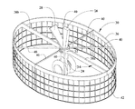
An embodiment of the safety zone fence (SZF) 30 is shown in FIG. 3. A collar 32, which will be described in greater detail subsequently, is attached to nose gear leg 24 to secure the SZF to the nose gear 12. In other embodiments alternative attachment locations on the gear leg or other structure of the landing gear assembly may be employed to support and secure the SZF. A support frame 34 extends from the collar and includes a perimeter hoop 36 surrounding the landing gear 12 and spaced from the collar 32 by fore and aft struts 38 a and 38 b and spokes 40. While shown as differing in geometric configuration in the embodiments of the drawings, the struts and spokes may be of common shape. The struts and spokes provide structural support to suspend the perimeter hoop 36 and prevent radial deformation of the perimeter hoop. A mesh skirt 42 extends downward from the perimeter hoop 36 to establish the safety zone and prevent encroachment into the safety zone by personnel. Height of the perimeter hoop 36 establishes a top or first level of the safety zone and the mesh skirt extends downward substantially to ground level. The struts 38 a, 38 b, spokes 40, perimeter hoop 36 and mesh skirt 42 may be metal, such as aluminum or light weight steel or rigid plastic or composite material with sufficient strength to physically displace a person from the path of the landing gear 12 while in motion or, as a minimum, restrain the person from engaging the landing gear tires. Sufficient rigidity is provided to allow a person contacting the SZF to grasp the structure to stabilize themselves to prevent falling if contacted by the SZF. The embodiment shown in the drawings is elliptical in shape however a circular, quadrilateral or other alternative geometric shape may be employed.
Details of an exemplary collar 32 are shown in FIGS. 4A, 4B and 4C. Collar 32 is adapted to be secured on the gear leg 24. For the embodiment shown, an indexing key 44 extends from the gear leg 24 and is received in a mating aperture 46 in the collar as best seen in FIG. 4A. The key may be an existing structural element on the landing gear leg 24 or an added member. For the embodiment shown, the key 44 additionally provides vertical support for the collar 32. For the embodiment shown, the SZF is bifurcated on the minor axis for attachment and disassembly from the gear leg. The collar 32 is bifurcated for attachment around the gear leg 24 and mating halves of the collar 32 a and 32 b may be secured with a boss 48 extending from a forward half of the collar and fasteners 50 extending through the boss into the rear half of the collar as best seen in FIG. 4B. For the embodiment shown in the drawings and detailed in FIG. 4C, cinch blocks 52 extend from the forward and rear halves of the collar 32 and receive a threaded fastener 54 to circumferentially tension the collar around the gear leg 24. While shown in the drawings as a hex head bolt, the fastener may be a hand tightened clamp such as a wing nut or self-ratcheting handle. Friction created by the collar prevents turning of the assembled SZF on the gear leg and provides vertical support to allow the landing gear 12 to carry the SZF.
As shown in FIG. 5, the SZF 30 may be separated for attachment and removal from the landing gear 12. A forward section 30 a and a rear section 30 b are positioned in front of and behind the landing gear as shown. The elements are then brought together and the forward and rear elements of the collar 32 a and 32 b are secured as previously described. The assembled SZF then provides the secure zone as shown in FIG. 3. In alternative embodiments, the forward and rear elements of the collar 32 a and 32 b may be separately mounted on the gear leg 12. Struts 38 a, 38 b and spokes 40 may then be inserted in keyed slots 56 or similar attachments in the collar as shown in FIG. 6.
A second embodiment of the SZF employing separate segmented elements forming the perimeter hoop and mesh skirt as shown in FIG. 7. Hoop segments 36 a, 36 b, 36 c and 36 d may be employed to form the forward section 30 a of the SZF supporting mesh skirt segments 42 a, 42 b, 42 c and 42 d (while shown as flat segments the hoop and mesh skirt segments may be arcuate). The struts as exemplified by forward strut 38 a and spokes 40 employ connection assemblies 100 to removably support the hoop segments and, in turn are removably supported on hooks 102 extending from the collar 32. As shown in detail in FIG. 8, collar 32 may employ upper hooks 102 a and lower hooks 104 to provide additional rigidity to receive the mating apertured flanges 106 and 108 respectively of the strut 38 a as shown in detail in FIG. 9. The spokes 40 may be bifurcated adjacent the collar providing angled arms 41 to attach to the lower hooks (as best seen in FIG. 7). Similarly, the connection assembly 100 on the struts and spokes may employ upper hooks 110 and lower hooks 112 to be received in the mating apertured flanges 114 on the perimeter hoop sections. Cotter pins or similar securing elements may be employed to secure the assembled aperture flanges on the hooks.
As yet another alternative, the struts 38 a, 38 b and/or spokes 40 may be pivotally mounted to the collar 32 with hinges 57 and perimeter hoop 36 and skirt 42 may be equipped with multiple hinges 58 to allow them to be collapsed in accordion pleats as shown in FIG. 10.
The embodiment of the SZF as shown in FIGS. 3 and 5 may be carried stored and transported on a tow tug 64 with a rack adapted to engage the spokes 40 as shown in FIGS. 11A and 11B. A separate trailer may be employed to carry the SZF elements and towed by the tug. One or more cylindrical posts 60 extending from a rear deck 62 of the tug are engaged between the spokes to support the SZF halves 30 aand 30 b which are nested. Alternative vertical suspending racks may also be employed.
Similarly, the perimeter hoop sections of the second embodiment of the SZF shown in FIG. 7 may be disassembled and stored on the cylindrical racks of the tug with additional brackets 64 or support for the struts and spokes as shown in FIGS. 12A and 12B
The embodiments disclosed provide a method for landing gear safety by attaching a collar to a landing gear leg and spacing a perimeter hoop from the collar. A mesh skirt is then extended from the perimeter hoop to near ground level. Spacing of the perimeter hoop may be accomplished by attaching struts between the collar and perimeter hoop. The struts may be attached by inserting the struts in keyed slots in the collar or rigidly secured by welding or other means. The perimeter hoop and mesh skirt may also be hinged for accordion pleat folding.
Having now described various embodiments of the disclosure in detail as required by the patent statutes, those skilled in the art will recognize modifications and substitutions to the specific embodiments disclosed herein. Such modifications are within the scope and intent of the present disclosure as defined in the following claims.

Claims (19)

What is claimed is:
1. A safety device to separate personnel from landing gear tires, said safety device comprising:
a clamping collar configured to wrap around a landing gear post;
a support frame extending radially outward from said clamping collar that defines at least part of a perimeter surrounding the landing gear; and
a mesh skirt extending downward from said support frame substantially to ground level;
wherein the mesh skirt is substantially perpendicular to ground level.
2. The safety device according to claim 1 wherein said mesh skirt is configured to engage a person such that the person is restrained from engaging the landing gear tires.
3. The safety device according to claim 1 wherein said support frame is operable to support a person that holds onto said support frame.
4. The safety device according to claim 1 wherein said support frame and said mesh. skirt in combination are configured to provide a continuous barrier around the landing gear from a first level downward to a ground level.
5. The safety device according to claim 1 wherein said clamping collar includes a clamp that can be tightened by hand.
6. The safety device according to claim 1 wherein said support frame is collapsible in sections and configurable for storage on a rack attached to a tow tug.
7. A safety zone fence for aircraft landing gear comprising:
a collar concentrically received on a landing gear leg;
a support frame extending from the collar and having
a perimeter hoop radially spaced from the collar,
a plurality of struts attaching the perimeter hoop to the collar, and,
a mesh skirt extending downward from the perimeter hoop substantially to ground level;
wherein the mesh skirt is substantially perpendicular to ground level.
8. The safety zone fence as defined in claim 7 wherein the collar and the support frame are bifurcated tier attachment to and removal from the landing gear leg.
9. The safety zone fence as defined in claim 7 wherein the support frame is made from material selected from the set of aluminum, light weight steel, rigid plastic and composite materials.
10. The safety zone fence as defined in claim 7 wherein the mesh skirt is made from material selected from the set of aluminum, light weight steel, rigid plastic and composite materials.
11. The safety zone fence as defined in claim 7 further comprising an indexing post extending from the landing gear leg and received in an aperture in the collar.
12. The safety zone fence as defined in claim 7 wherein the struts are removably attached to the collar.
13. The safety zone fence as defined in claim 7 wherein the struts are attached to the collar with hinges.
14. The safety zone fence as defined in claim 7 wherein the perimeter hoop and mesh skirt are hinged to be collapsed in accordion pleats.
15. The safety zone fence as defined in claim 7 wherein the perimeter hoop is elliptical.
16. A method for landing gear safety comprising:
attaching a collar to a landing gear leg;
spacing a perimeter hoop from the collar to surround the landing gear leg; and,
extending a mesh skirt from the perimeter hoop to near ground level;
wherein the mesh skirt is substantially perpendicular to ground level.
17. The method of claim 16 further wherein the step of spacing a perimeter hoop includes attaching struts between the collar and perimeter hoop.
18. The method of claim 17 wherein attaching the struts includes inserting the struts in keyed slots in the collar.
19. The method of claim 17 wherein attaching the struts includes hinging the struts from the collar and hinging the perimeter hoop and mesh skirt for accordion pleat folding.
US13/663,717 2012-10-30 2012-10-30 Temporary clamp-on landing gear wheel safety zone fence Active 2033-03-15 US8931735B2 (en)

Priority Applications (2)

Application Number Priority Date Filing Date Title
US13/663,717 US8931735B2 (en) 2012-10-30 2012-10-30 Temporary clamp-on landing gear wheel safety zone fence
PCT/US2013/064339 WO2014070407A2 (en) 2012-10-30 2013-10-10 Temporary clamp-on landing gear wheel safety zone fence

Applications Claiming Priority (1)

Application Number Priority Date Filing Date Title
US13/663,717 US8931735B2 (en) 2012-10-30 2012-10-30 Temporary clamp-on landing gear wheel safety zone fence

Publications (2)

Publication Number Publication Date
US20140117155A1 US20140117155A1 (en) 2014-05-01
US8931735B2 true US8931735B2 (en) 2015-01-13

Family

ID=49474722

Family Applications (1)

Application Number Title Priority Date Filing Date
US13/663,717 Active 2033-03-15 US8931735B2 (en) 2012-10-30 2012-10-30 Temporary clamp-on landing gear wheel safety zone fence

Country Status (2)

Country Link
US (1) US8931735B2 (en)
WO (1) WO2014070407A2 (en)

Families Citing this family (1)

* Cited by examiner, † Cited by third party
Publication number Priority date Publication date Assignee Title
US11220311B2 (en) * 2019-02-08 2022-01-11 Cross Pipes Development Llc Watercraft and aircraft bladder and tie down securing apparatuses and methods

Citations (16)

* Cited by examiner, † Cited by third party
Publication number Priority date Publication date Assignee Title
US108280A (en) * 1870-10-11 Improvement in tree-boxes
US472137A (en) * 1892-04-05 Tree-protector
US514306A (en) * 1894-02-06 Patrick clines
GB557444A (en) 1942-02-10 1943-11-22 Phillips & Powis Aircraft Ltd Improvements relating to retractable undercarriages for aircraft
US2572342A (en) * 1946-09-03 1951-10-23 James C Huett Aircraft mudguard
US3866860A (en) 1973-09-24 1975-02-18 Sr John M Opitz Airplane wheel rotator
US3972493A (en) * 1975-01-29 1976-08-03 Milne William G Docking device for a dirigible
SU296384A1 (en) 1969-04-25 1976-08-25 Aircraft Air Bed Chassis
US4936420A (en) * 1989-06-05 1990-06-26 Nenstiel Frank S Taxiguard
US5058827A (en) * 1989-12-07 1991-10-22 Mcdonnell Douglas Corporation Super debris deflector
US5427210A (en) * 1994-03-14 1995-06-27 Willaford; Kenneth Wheel chock for aircraft
US6007023A (en) * 1998-07-13 1999-12-28 Lockheed Martin Corporation Cable restraint system for aircraft engine run-up tests
US6896223B2 (en) * 2002-12-04 2005-05-24 Miti Manufacturing Company Aircraft wheel immobilizer
US7059567B1 (en) * 2005-02-02 2006-06-13 Dino Scorziello Small weapons shield for helicopters
US20070095977A1 (en) * 2005-10-31 2007-05-03 The Boeing Company Mesh fender for protecting an aircraft against damage from foreign objects
JP2007276751A (en) 2006-04-12 2007-10-25 Kawasaki Heavy Ind Ltd All wind direction movable blast fence device

Patent Citations (16)

* Cited by examiner, † Cited by third party
Publication number Priority date Publication date Assignee Title
US108280A (en) * 1870-10-11 Improvement in tree-boxes
US472137A (en) * 1892-04-05 Tree-protector
US514306A (en) * 1894-02-06 Patrick clines
GB557444A (en) 1942-02-10 1943-11-22 Phillips & Powis Aircraft Ltd Improvements relating to retractable undercarriages for aircraft
US2572342A (en) * 1946-09-03 1951-10-23 James C Huett Aircraft mudguard
SU296384A1 (en) 1969-04-25 1976-08-25 Aircraft Air Bed Chassis
US3866860A (en) 1973-09-24 1975-02-18 Sr John M Opitz Airplane wheel rotator
US3972493A (en) * 1975-01-29 1976-08-03 Milne William G Docking device for a dirigible
US4936420A (en) * 1989-06-05 1990-06-26 Nenstiel Frank S Taxiguard
US5058827A (en) * 1989-12-07 1991-10-22 Mcdonnell Douglas Corporation Super debris deflector
US5427210A (en) * 1994-03-14 1995-06-27 Willaford; Kenneth Wheel chock for aircraft
US6007023A (en) * 1998-07-13 1999-12-28 Lockheed Martin Corporation Cable restraint system for aircraft engine run-up tests
US6896223B2 (en) * 2002-12-04 2005-05-24 Miti Manufacturing Company Aircraft wheel immobilizer
US7059567B1 (en) * 2005-02-02 2006-06-13 Dino Scorziello Small weapons shield for helicopters
US20070095977A1 (en) * 2005-10-31 2007-05-03 The Boeing Company Mesh fender for protecting an aircraft against damage from foreign objects
JP2007276751A (en) 2006-04-12 2007-10-25 Kawasaki Heavy Ind Ltd All wind direction movable blast fence device

Also Published As

Publication number Publication date
US20140117155A1 (en) 2014-05-01
WO2014070407A2 (en) 2014-05-08
WO2014070407A3 (en) 2014-07-10

Similar Documents

Publication Publication Date Title
US8434274B2 (en) Raptor nest exclusion device
US9637356B2 (en) Collapsible hoisting apparatus
KR20180050154A (en) Apparatus for installing fall protector net, and method thereof
US20100253023A1 (en) Wild game cart
US9623924B2 (en) Cart
US9353726B2 (en) Rotor hub maintenance system
US9137982B2 (en) Convertible treestand
US8931735B2 (en) Temporary clamp-on landing gear wheel safety zone fence
CN102278287A (en) Wind turbine nacelle, transport system for a wind turbine nacelle and method for transporting a wind turbine nacelle
CN107867410A (en) Drop protection system and method
US20140283731A1 (en) Aerial marker assemblies, components and related methods
US7216604B2 (en) Retractable arch system for a boat
US20110291062A1 (en) Self help ladder and securing device
US8556277B1 (en) Wheeled device to assist in carrying ladders
US20110139845A1 (en) Tree stand transporter
KR102100403B1 (en) Take Off And Landing apparatus for powered paraglider
US10595526B1 (en) Big-game towing hitch yoke
SE537703C2 (en) Mounting device for an external switchable component
CN206383891U (en) Erecting device for the cat ladder component of machine
JP3232384U (en) Fall prevention device during loading platform work
CN102712067A (en) Method of operating a flow line, an assembly trailer, a tow bar, and a heavy machine installed on an assembly trailer and a flow line
JP3232384U7 (en)
CN104353580B (en) A kind of spraying coating line being exclusively used in automotive hub
KR101694817B1 (en) The rack of the towing bicycle
US9456598B1 (en) Mobile hunting platform

Legal Events

Date Code Title Description
AS Assignment

Owner name: THE BOEING COMPANY, ILLINOIS

Free format text: ASSIGNMENT OF ASSIGNORS INTEREST;ASSIGNOR:JONES, JOHNATHA M.;REEL/FRAME:029210/0795

Effective date: 20121030

STCF Information on status: patent grant

Free format text: PATENTED CASE

MAFP Maintenance fee payment

Free format text: PAYMENT OF MAINTENANCE FEE, 4TH YEAR, LARGE ENTITY (ORIGINAL EVENT CODE: M1551)

Year of fee payment: 4

MAFP Maintenance fee payment

Free format text: PAYMENT OF MAINTENANCE FEE, 8TH YEAR, LARGE ENTITY (ORIGINAL EVENT CODE: M1552); ENTITY STATUS OF PATENT OWNER: LARGE ENTITY

Year of fee payment: 8