US8931164B2 - Printing method with pivotable duplexing unit - Google Patents
Printing method with pivotable duplexing unit Download PDFInfo
- Publication number
- US8931164B2 US8931164B2 US13/118,656 US201113118656A US8931164B2 US 8931164 B2 US8931164 B2 US 8931164B2 US 201113118656 A US201113118656 A US 201113118656A US 8931164 B2 US8931164 B2 US 8931164B2
- Authority
- US
- United States
- Prior art keywords
- duplexing unit
- duplexing
- unit
- support member
- printer
- Prior art date
- Legal status (The legal status is an assumption and is not a legal conclusion. Google has not performed a legal analysis and makes no representation as to the accuracy of the status listed.)
- Expired - Fee Related, expires
Links
Images


Classifications
-
- B—PERFORMING OPERATIONS; TRANSPORTING
- B41—PRINTING; LINING MACHINES; TYPEWRITERS; STAMPS
- B41J—TYPEWRITERS; SELECTIVE PRINTING MECHANISMS, i.e. MECHANISMS PRINTING OTHERWISE THAN FROM A FORME; CORRECTION OF TYPOGRAPHICAL ERRORS
- B41J3/00—Typewriters or selective printing or marking mechanisms characterised by the purpose for which they are constructed
- B41J3/60—Typewriters or selective printing or marking mechanisms characterised by the purpose for which they are constructed for printing on both faces of the printing material
-
- B—PERFORMING OPERATIONS; TRANSPORTING
- B41—PRINTING; LINING MACHINES; TYPEWRITERS; STAMPS
- B41J—TYPEWRITERS; SELECTIVE PRINTING MECHANISMS, i.e. MECHANISMS PRINTING OTHERWISE THAN FROM A FORME; CORRECTION OF TYPOGRAPHICAL ERRORS
- B41J11/00—Devices or arrangements of selective printing mechanisms, e.g. ink-jet printers or thermal printers, for supporting or handling copy material in sheet or web form
- B41J11/006—Means for preventing paper jams or for facilitating their removal
-
- Y—GENERAL TAGGING OF NEW TECHNOLOGICAL DEVELOPMENTS; GENERAL TAGGING OF CROSS-SECTIONAL TECHNOLOGIES SPANNING OVER SEVERAL SECTIONS OF THE IPC; TECHNICAL SUBJECTS COVERED BY FORMER USPC CROSS-REFERENCE ART COLLECTIONS [XRACs] AND DIGESTS
- Y10—TECHNICAL SUBJECTS COVERED BY FORMER USPC
- Y10T—TECHNICAL SUBJECTS COVERED BY FORMER US CLASSIFICATION
- Y10T29/00—Metal working
- Y10T29/49—Method of mechanical manufacture
- Y10T29/49002—Electrical device making
- Y10T29/4902—Electromagnet, transformer or inductor
-
- Y—GENERAL TAGGING OF NEW TECHNOLOGICAL DEVELOPMENTS; GENERAL TAGGING OF CROSS-SECTIONAL TECHNOLOGIES SPANNING OVER SEVERAL SECTIONS OF THE IPC; TECHNICAL SUBJECTS COVERED BY FORMER USPC CROSS-REFERENCE ART COLLECTIONS [XRACs] AND DIGESTS
- Y10—TECHNICAL SUBJECTS COVERED BY FORMER USPC
- Y10T—TECHNICAL SUBJECTS COVERED BY FORMER US CLASSIFICATION
- Y10T29/00—Metal working
- Y10T29/49—Method of mechanical manufacture
- Y10T29/49401—Fluid pattern dispersing device making, e.g., ink jet
-
- Y—GENERAL TAGGING OF NEW TECHNOLOGICAL DEVELOPMENTS; GENERAL TAGGING OF CROSS-SECTIONAL TECHNOLOGIES SPANNING OVER SEVERAL SECTIONS OF THE IPC; TECHNICAL SUBJECTS COVERED BY FORMER USPC CROSS-REFERENCE ART COLLECTIONS [XRACs] AND DIGESTS
- Y10—TECHNICAL SUBJECTS COVERED BY FORMER USPC
- Y10T—TECHNICAL SUBJECTS COVERED BY FORMER US CLASSIFICATION
- Y10T29/00—Metal working
- Y10T29/49—Method of mechanical manufacture
- Y10T29/49826—Assembling or joining
Definitions
- the present invention relates generally to a media path for a printing apparatus, and more particularly to a duplexing unit for reversing a side of the media facing a print region.
- a duplexing unit is provided as a removable auxiliary unit that the user can decide whether or not to purchase, according to his printing needs. If the user does purchase the auxiliary duplexing unit, he needs to install it himself, thus increasing the complexity of the setting up of the printing apparatus.
- U.S. Pat. Nos. 4,825,245, 4,884,110, 6,564,019 and 7,536,133 have disclosed hinged duplexing units for electrostatic printers such as laser printers. Due to the configuration of such printers the duplexing unit was not located near a base of the unit. The hinges of the duplexing units as disclosed in these patents were configured to be horizontal (i.e. parallel to the base), so that the duplexing unit is configured to pivot upward or downward.
- the printer In a low-cost desktop printer, such as an inkjet printer, the printer is intended to sit on the user's desk or other flat surface that extends beyond the base of the printer.
- the duplexing unit is typically located very close to the base of the printer.
- a horizontal hinge configuration has disadvantages. If the hinge is located at the top of the duplexing unit, the duplexing unit would pivot upwards. However, since the user is typically taller than the desktop, the upwardly pivoted duplexing unit would obscure visibility and interfere with access to the media paths inside.
- duplexing unit Even if the user bent over so that his eyes were at desktop level, it would make it difficult to reach in and clear out paper jams between the upwardly pivoted duplexing unit and the desktop. If the hinge is located at the bottom of the duplexing unit, the duplexing unit would pivot downwards. However, if the duplexing unit is located very near the base of the printing apparatus, its pivoting motion would typically cause it to hit the desktop before opening all the way, again interfering with visibility and access to the media paths for clearing paper jams.
- duplexing unit that does not require user installation, and that allows good visibility and access to media paths inside the printing apparatus in order to facilitate clearing out paper jams.
- a preferred embodiment of the present invention includes a method of making a printer comprising forming a pin member portion of a hinge on a first end of a duplexing unit of the printer and forming a support member portion of a hinge on a housing of the printer.
- a unique feature of the duplexing unit is that it does not contain any motor driven rollers for moving a media sheet.
- the support member and the pin member are oriented vertically.
- the duplexing unit provides a media pathway for printing on both sides of printer media and its hinged connection to the printer allows the duplexing unit to swing open and closed horizontally as a household interior door would.
- a latch projection on a second end of the duplexing unit opposite the hinge allows the duplexing unit to be securely closed.
- a hole formed in the printer catches the latch projection and keeps the duplexing unit closed until it is manually unlatched.
- the pin member is coupled to the support member allowing the duplexing unit to freely pivot about the vertical rotational axis formed by the joined pin member and the support member. It also enables the duplexing unit to pivot to a closed position wherein the hole in the printer catches the latch projection.
- the support member includes a bearing surface formed thereon that is substantially horizontal and the pin member makes pivotable contact with this bearing surface.
- a spring attached to the duplexing unit at the hinge end biases the latch projection to so that it remains inserted into the hole until it is manually unlatched.
- the end of the pin member is shaped as a D, having a rounded side and a flat side, wherein the round side portion of the D shape is contacting a face of the support member when the duplexing unit is in the closed position and is not contacting the face of the support member when the duplexing unit is in the open position.
- a screw can be used to secure the pin member to the support member.
- the duplexing unit comprises an S shaped inner guide member formed thereon.
- the printer includes a corresponding duplexing media path support member wherein the duplexing media path support member closely faces a portion of the S shaped inner guide member when the duplexing unit is in the closed position for allowing a media sheet to travel therethrough.
- the duplexing unit includes a latch for affixing the inner guide member to the duplexing unit.
- Another preferred embodiment of the present invention includes a method of accessing a paper path of a printer comprising pivoting a duplexing unit of the printer along a horizontal plane for exposing the paper path.
- the duplexing unit is pivoted about a vertical axis produced by a pin member formed on the duplexing unit which is joined to a support member formed on a housing of the printer.
- a round portion of the pin member contacts a face of the support member when the duplexing unit is swung, or pivoted, shut to a closed position.
- the round portion of the pin member loses contact with the face of the support member when the duplexing unit is manually unlatched and swung, or pivoted, open.
- Pivoting open the duplexing unit comprises unlatching the latched end of the duplexing unit and pivoting the duplexing unit about a vertical axis at the hinged end of the duplexing unit opposite the latched end.
- the duplexing unit includes a horizontal dimension that is greater than its vertical dimension and so the horizontal pivoting of the duplexing unit sweeps a greater area in a horizontal plane than it would in a vertical plane if the duplexing unit was designed to open vertically, such as discussed above with regard to the prior art, opened vertically.
- Another preferred embodiment of the present invention includes a method of making a printer comprising joining a duplexing unit of a printer to the housing of the printer using a vertically oriented hinge wherein the duplexing unit includes a first part of the hinge and the printer includes a second part of the hinge. This allows the duplexing unit to pivot along a horizontal plane between an open position and a closed position.
- Joining the duplexing unit to the printer comprises forming a pin member on one end of the duplexing unit oriented in a vertical direction, and forming a support member on the housing of the printer also oriented in a vertical direction for being joined to the pin member.
- a latch projection on the other end of the duplexing unit corresponds to a hole in the printer for catching the latch projection to keep closed in an operational position the duplexing unit.
- the duplexing unit When the duplexing unit is in an open position the media pathway is accessible to remove jammed paper, for example, and such an open position is not typically a normal operating mode of the printer.
- FIG. 1 is a schematic representation of an inkjet printer system
- FIG. 2 is a perspective view of a portion of a printhead chassis
- FIG. 3 is a perspective view of a portion of a desktop carriage printer
- FIG. 4 is a schematic side view of an exemplary media path in a carriage printer that includes a duplexing unit
- FIG. 5 is a schematic side view of the media path of FIG. 4 , where one side of the sheet has been printed and the sheet is travelling toward the duplexing unit;
- FIG. 6 is a schematic side view of the media path of FIG. 4 , where one side of the sheet has been printed and the sheet is travelling through the duplexing unit to orient the opposite side of the sheet toward the print region;
- FIG. 7 is a schematic side view of the media path of FIG. 4 , where the lead edge of the sheet has exited the duplexing unit and is approaching the print region;
- FIG. 8 is a perspective view of a printing apparatus with a pivotable duplexing unit according to a preferred embodiment of the invention.
- FIG. 9 is a rotated perspective view of the printing apparatus of FIG. 8 ;
- FIG. 10 is a perspective view of the printing apparatus of FIG. 8 with the pivotable duplexing unit in a closed position;
- FIGS. 11 and 12 are close-up perspective views of a portion of a hinge for the pivotable duplexing unit of FIG. 8 ;
- FIGS. 13 and 14 are perspective views of the pivotable duplexing unit of FIG. 8 ;
- FIG. 15 is a rotated perspective view of the printing apparatus of FIG. 8 ;
- FIG. 16 is a perspective view of the pivotable duplexing unit of FIG. 8 ;
- FIGS. 17-20 are perspective views of various portions of the pivotable duplexing unit of FIG. 8 ;
- FIG. 21 is a perspective view of a portion of the pivotable duplexing unit of FIG. 8 according to another preferred embodiment of the invention.
- Inkjet printer system 10 includes an image data source 12 , which provides data signals that are interpreted by a controller 14 as being commands to eject drops.
- Controller 14 includes an image processing unit 15 for rendering images for printing, and outputs signals to an electrical pulse source 16 of electrical energy pulses that are inputted to an inkjet printhead 100 , which includes at least one inkjet printhead die 110 .
- Nozzles 121 in the first nozzle array 120 have a larger opening area than nozzles 131 in the second nozzle array 130 .
- each of the two nozzle arrays has two staggered rows of nozzles, each row having a nozzle density of 600 per inch.
- ink delivery pathway 122 is in fluid communication with the first nozzle array 120
- ink delivery pathway 132 is in fluid communication with the second nozzle array 130 .
- Portions of ink delivery pathways 122 and 132 are shown in FIG. 1 as openings through printhead die substrate 111 .
- One or more inkjet printhead die 110 will be included in inkjet printhead 100 , but for greater clarity only one inkjet printhead die 110 is shown in FIG. 1 .
- first fluid source 18 supplies ink to first nozzle array 120 via ink delivery pathway 122
- second fluid source 19 supplies ink to second nozzle array 130 via ink delivery pathway 132 .
- distinct fluid sources 18 and 19 are shown, in some applications it may be beneficial to have a single fluid source supplying ink to both the first nozzle array 120 and the second nozzle array 130 via ink delivery pathways 122 and 132 respectively. Also, in some embodiments, fewer than two or more than two nozzle arrays can be included on printhead die 110 . In some embodiments, all nozzles on inkjet printhead die 110 can be the same size, rather than having multiple sized nozzles on inkjet printhead die 110 .
- Drop forming mechanisms can be of a variety of types, some of which include a heating element to vaporize a portion of ink and thereby cause ejection of a droplet, or a piezoelectric transducer to constrict the volume of a fluid chamber and thereby cause ejection, or an actuator which is made to move (for example, by heating a bi-layer element) and thereby cause ejection.
- electrical pulses from electrical pulse source 16 are sent to the various drop ejectors according to the desired deposition pattern. In the example of FIG.
- droplets 181 ejected from the first nozzle array 120 are larger than droplets 182 ejected from the second nozzle array 130 , due to the larger nozzle opening area.
- droplets 181 ejected from the first nozzle array 120 are larger than droplets 182 ejected from the second nozzle array 130 , due to the larger nozzle opening area.
- drop forming mechanisms (not shown) associated respectively with nozzle arrays 120 and 130 are also sized differently in order to optimize the drop ejection process for the different sized drops.
- droplets of ink are deposited on a recording medium 20 .
- FIG. 2 shows a perspective view of a portion of a printhead chassis 250 , which is an example of an inkjet printhead 100 .
- Printhead chassis 250 includes three printhead die 251 (similar to printhead die 110 in FIG. 1 ), each printhead die 251 containing two nozzle arrays 253 , so that printhead chassis 250 contains six nozzle arrays 253 altogether.
- the six nozzle arrays 253 in this example can each be connected to separate ink sources (not shown in FIG. 2 ); such as cyan, magenta, yellow, text black, photo black, and a colorless protective printing fluid.
- Each of the six nozzle arrays 253 is disposed along nozzle array direction 254 , and the length of each nozzle array along the nozzle array direction 254 is typically on the order of 1 inch or less. Typical lengths of recording media are 6 inches for photographic prints (4 inches by 6 inches) or 11 inches for paper (8.5 by 11 inches). Thus, in order to print a full image, a number of swaths are successively printed while moving printhead chassis 250 across the recording medium 20 . Following the printing of a swath, the recording medium 20 is advanced along a media advance direction that is substantially parallel to nozzle array direction 254 .
- a flex circuit 257 to which the printhead die 251 are electrically interconnected, for example, by wire bonding or TAB bonding. The interconnections are covered by an encapsulant 256 to protect them. Flex circuit 257 bends around the side of printhead chassis 250 and connects to connector board 258 . When printhead chassis 250 is mounted into the carriage 200 (see FIG. 3 ), connector board 258 is electrically connected to a connector (not shown) on the carriage 200 , so that electrical signals can be transmitted to the printhead die 251 .
- FIG. 3 shows a portion of a desktop carriage printer. Some of the parts of the printer have been hidden in the view shown in FIG. 3 so that other parts can be more clearly seen.
- Printing apparatus 300 has a print region 303 across which carriage 200 is moved back and forth in carriage scan direction 305 along the X axis, between the right side 306 and the left side 307 of printing apparatus 300 , while drops are ejected from printhead die 251 (not shown in FIG. 3 ) on printhead chassis 250 that is mounted on carriage 200 .
- Carriage motor 380 moves belt 384 to move carriage 200 along carriage guide rail 382 .
- An encoder sensor (not shown) is mounted on carriage 200 and indicates carriage location relative to an encoder fence 383 .
- Printhead chassis 250 is mounted in carriage 200 , and multi-chamber ink tank 262 and single-chamber ink tank 264 are mounted in the printhead chassis 250 .
- the mounting orientation of printhead chassis 250 is rotated relative to the view in FIG. 2 , so that the printhead die 251 are located at the bottom side of printhead chassis 250 , the droplets of ink being ejected downward onto the recording medium in print region 303 in the view of FIG. 3 .
- Multi-chamber ink tank 262 contains five ink sources: cyan, magenta, yellow, photo black, and colorless protective fluid; while single-chamber ink tank 264 contains the ink source for text black.
- Paper or other recording medium (sometimes generically referred to as paper or media herein) is loaded along paper load entry direction 302 toward the front of printing apparatus 308 .
- the motor that powers the media advance rollers is not shown in FIG. 3 , but the hole 310 at the right side of the printing apparatus 306 is where the motor gear (not shown) protrudes through in order to engage feed roller gear 311 , as well as the gear for the discharge roller (not shown). A forward direction of rotation 313 is indicated.
- the electronics board 390 Toward the rear of the printing apparatus 309 is located the electronics board 390 , which includes cable connectors 392 for communicating via cables (not shown) to the printhead carriage 200 and from there to the printhead chassis 250 . Also on the electronics board are typically mounted motor controllers for the carriage motor 380 and for the paper advance motor, a processor and/or other control electronics (shown schematically as controller 14 and image processing unit 15 in FIG. 1 ) for controlling the printing process, and an optional connector for a cable to a host computer.
- the media advance system includes a variety of rollers that are used to advance the medium through the printer as shown schematically in the side view of FIG. 4 .
- a media input holder 316 which is located at a plane near the base 301 and is substantially parallel to base 301 , holds a stack of media 370 .
- a pick roller 320 is driven to rotate in forward rotation direction 313 to advance the top sheet 371 of the stack of media 370 from media input holder 316 along paper load entry direction 302 and up inclined guide 317 .
- a turn roller 322 is driven to further advance the sheet of media 371 received from the pick roller around a C-shaped path (in cooperation with a curved rear wall surface and a pinch roller 321 ).
- the sheet 371 continues to advance along media advance direction 304 from the rear 309 of the printing apparatus (with reference also to FIG. 3 ) toward the print region 303 that is located at a plane that is farther from base 301 than the media input holder 316 is.
- the sheet 371 is then advanced by feed roller 312 (driven to rotate in forward rotation direction 313 ) and idler roller(s) 323 to advance the lead edge 375 of sheet 371 to and across print region 303 for printing on first side 372 of sheet 371 , and from there to a discharge roller 324 and star wheel(s) 325 .
- Feed roller 312 includes a feed roller shaft along its axis, and feed roller gear 311 is mounted on the feed roller shaft.
- Feed roller 312 can include a separate roller mounted on the feed roller shaft, or can include a thin high friction coating on the feed roller shaft.
- a rotary encoder (not shown) can be coaxially mounted on the feed roller shaft in order to monitor the angular rotation of the feed roller.
- a media end sensor 315 is positioned near feed roller 312 between turn roller 322 and feed roller 312 in order to detect when a sheet of media is approaching the feed roller 312 .
- the sheet 371 has pushed the media end sensor 315 down.
- duplexing unit 350 that includes a duplexing media path 351 for reversing the sheet 371 of media in order to print on a second side 373 of the sheet that is opposite first side 372 .
- duplexing unit 350 is pivotably mounted in order to provide accessibility for clearing paper jams.
- a duplexing media path support member 335 is configured to face the pivotable duplexing unit 350 when the pivotable duplexing unit 350 is in a closed position.
- the portion of the duplexing media path 351 that is included in the pivotable duplexing unit 350 includes an inner guide member 352 that is adjacent the duplexing media support member 335 when the pivotable duplexing unit 350 is in a closed position; an inner cover member 354 that is adjacent the inner guide member 352 ; and an outer cover member 356 that is adjacent the inner cover member 354 . As can be seen in FIG.
- the surface of inner guide member 352 has a first curvature near base 301 , and a second curvature farther from base 301 , where the second curvature has an opposite sense from the first curvature, so that the surface of inner guide member 352 is somewhat an inverted S-shape (or S-shaped as seen from the opposite perspective from the view shown in FIG. 4 ).
- inner cover member 354 includes a curved surface and outer cover member 356 includes a curved surface, such that the curved surface of inner cover member 354 faces and is spaced apart from the curved surface of outer cover member 356 .
- FIGS. 5 to 7 show a sequence of positions of a sheet 371 of media as it approaches the duplexing unit 350 ( FIG. 5 ), travels through duplexing unit 350 until the end of sheet 371 reaches turn roller 322 ( FIG. 6 ), and is advanced by turn roller 322 toward feed roller 312 with second side 373 of sheet 371 now facing the print region 303 ( FIG. 7 ).
- feed roller 312 and discharge roller 324 are driven to rotate in reverse rotation direction 314 to move sheet 371 toward duplexing unit 350 .
- Media end sensor 315 continues to be pushed down by sheet 371 .
- sheet 371 is still being moved by feed roller 312 (rotating in reverse rotation direction 314 ) through duplexing unit 350 , and the lead edge 375 of sheet 371 has just reached turn roller 322 .
- sheet 371 is still being moved by feed roller 312 (rotating in reverse rotation direction 314 ) through duplexing unit 350 , and the lead edge 375 of sheet 371 has just reached turn roller 322 .
- the media path from the feed roller 312 through duplexing media path 351 and to turn roller 322 is sufficiently short relative to the length of the media, then no drive rollers are required in duplexing unit 350 . This is advantageous because no gears are required to provide power to a powered roller within duplexing unit 350 .
- the media path from the feed roller 312 through duplexing media path 351 and to turn roller 322 is designed to be slightly shorter than 11 inches, so that both letter sized paper and A4 sized paper can be advanced through a duplexing unit 350 having no powered rollers within the duplexing unit.
- the controller would not be able to determine when to change the direction of rotation of feed roller 312 from reverse rotation direction 314 to forward rotation direction 313 in order to advance lead edge 375 of sheet 371 to print region 303 in order to print second side 373 .
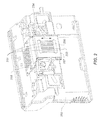
- FIG. 8 is a perspective view of printing apparatus 300 with a pivotable duplexing unit 350 in its open position according to a preferred embodiment of the invention. With reference to FIG. 3 , FIG. 8 also includes covers over the printer chassis framework, and the perspective is from the rear 309 of the printing apparatus.
- Printing apparatus 300 includes a base 301 to support the printing apparatus during operation.
- a wall 319 extends at an angle from base 301 . In the example of FIG. 8 , wall 319 is substantially perpendicular to base 301 .
- Pivotable duplexing unit 350 is attached to wall 319 using a hinge 340 having an axis 341 that is substantially perpendicular to base 301 .
- Duplexing unit 350 is pivotable about axis 341 in the directions indicated by the double headed curved arrow. Since the base 301 of printing apparatus 300 is substantially horizontal during operation, the axis 341 of hinge 340 is substantially vertical, unlike the horizontal hinges of the hinged duplexing units disclosed in U.S. Pat. Nos. 4,825,245, 4,884,110, 6,564,019 and 7,536,133 that were cited in the background. Thus, rather than pivoting upward or downward relative to the base 301 , pivotable duplexing unit 350 swings outward, sweeping out a path along a horizontal plane parallel to base 301 .
- pivotable duplexing unit 350 can be opened fully without interfering with the surface upon which base 301 rests, even though it is located close to the base 301 . Opening the pivotable duplexing unit 350 outward also does not result in the duplexing unit 350 obscuring visibility of media paths inside printing apparatus 300 .
- the configuration of hinge 340 with its axis 341 perpendicular to base 301 is advantageous, especially for desktop printers having the duplexing unit located close to the base 301 .
- FIG. 8 shows part of the securing mechanism for holding pivotable duplexing unit 350 in its closed position as it is in FIG. 10 .
- pegs 365 Located at the same end of pivotable duplexing unit 350 as hinge 340 are pegs 365 .
- pegs 365 enters holes 366 within the main body of printing apparatus 300 .
- FIG. 9 is a view that is rotated relative to FIG. 8 in order to show media input holder 316 and media output holder 318 .
- Pegs 365 and holes 366 are seen from a different perspective in FIG. 9 .
- FIG. 8 Also shown in FIG. 8 are items shown schematically in FIGS. 4-7 , including duplexing media support member 335 , inner guide member 352 , inner cover member 354 , outer cover member 356 and pinch rollers 321 . Curved surfaces of duplexing media support member 335 and inner guide member 352 are shown as being ribbed, in order to reduce friction against media being advanced through duplexing unit 350 . Not shown in FIG. 8 are the curved surfaces of inner cover member 354 or outer cover member 356 , or turn rollers 322 . Turn rollers 322 would line up with pinch rollers 321 when pivotable duplexing unit 350 is in a closed position, as it is in FIG. 10 .
- duplexing media support member 335 faces pivotable duplexing unit 350 .
- there are no powered rollers in some preferred embodiments of the duplexing unit 350 such as the example of FIG. 8 .
- the pivotable duplexing unit 350 if the pivotable duplexing unit 350 is in its open position, media advance for one-sided printing will not operate properly, as the media being advanced by the pick roller 320 ( FIG. 4 ) would tend to exit through the open duplexing unit 350 without reaching turn roller 322 .
- a scanning apparatus (not shown) is assembled on top of the upper surface 333 of the cover of printing apparatus 300 , i.e. the scanning apparatus is located farther from the base than pivotable duplexing unit 350 is.
- the scanning apparatus is pivoted upward from printing apparatus, the user can change ink tanks 262 and 264 ( FIG. 3 ) by reaching through access opening 334 .
- FIG. 11 is a close-up perspective view of the portion of printing apparatus 300 that includes the region of the hinge 340 , but with the pivotable duplexing unit hidden from view to show some details more clearly.
- wall, or housing, 319 includes a support member 342 of hinge 340 .
- FIG. 12 shows a similar portion of printing apparatus 300 , but from a more downward looking perspective than FIG. 11 in order to show the bearing surface 343 of support member 342 of hinge 340 for contacting an end of a pin member 344 ( FIG. 13 ). Also indicated in FIG. 12 is a contact face 348 for contacting a round edge of pin member 344 .
- FIG. 13 is a perspective view of the pivotable duplexing unit 350 , but with printing apparatus 300 hidden from view.
- Features of pivotable duplexing unit 350 described above relative to FIG. 8 are shown at higher magnification in FIG. 13 for better clarity.
- the entry 358 through which sheets of media enter the duplexing unit 350 and the exit 359 from which sheets of media exit the duplexing unit 350 are shown.
- pin member 344 of hinge 340 is shown.
- pin member 344 is not clearly seen, but with reference also to FIGS. 11 and 12 , pin member 344 is for pivoting relative to support member 342 of hinge 340 .
- An end 345 of pin member 344 makes pivotable contact with bearing surface 343 of support member 342 of hinge 340 ( FIG. 12 ).
- Also shown in FIG. 12 are screw holes 349 for screws to secure pin member 344 into support member 342 of hinge 340 .
- pivotable duplexing unit 350 includes a first end including at least one projection 360 for latching the pivotable duplexing unit 350 in a closed position, and a second end opposite the first end, where the second end includes the pin member 344 of the hinge 340 and a spring member 367 for biasing projection(s) 360 into corresponding hole(s) 361 ( FIG. 15 ) when pivotable duplexing unit 350 is in the closed position.
- the spring member can be attached to the duplexing unit by sliding it into a sleeve formed in the duplexing unit.
- projection 360 serves as a latch
- hole 361 serves as a catch for holding the pivotable duplexing unit in a closed position relative to the wall of the printing apparatus 360 .
- FIG. 14 is a close up view of the end of pivotable duplexing unit 350 that includes pin member 344 , spring member 367 and pegs 365 . Shown more clearly in FIG. 14 is a D shape 346 of the end 345 of pin member 344 . A round portion 347 of the D shape 346 is in contact with contact face 348 of support member 342 of hinge 340 ( FIG. 12 ) when the pivotable duplexing unit 350 is latched in the closed position. The round portion 347 at the top of pin member 344 makes the contact described with the contact face 348 at the top of support member 342 , and similarly contact is made between the round portion 347 at the bottom of pin member 344 with the contact face 348 at the bottom of support member 342 .
- the pivotable duplexing unit 350 compresses spring member 367 , and allows projections 360 ( FIG. 13 ) to come out of corresponding holes 361 ( FIG. 15 ).
- the pivotable duplexing unit 350 is pivoted with an unlatching force so that round portion 347 is no longer in contact with contact face 348 , further freedom of movement is provided.
- pin member 344 is part of outer cover member 356 .
- the pivotable duplexing unit 350 and printer housing 319 and their components as described herein are typically formed by injection molding.
- FIG. 15 shows a perspective view of printing apparatus 300 rotated in order to show holes 361 that serve as catches for latch projections 360 .
- FIG. 16 is a close-up view of pivotable duplexing unit 350 at the end including latch projections 360 .
- inner guide member 352 of pivotable duplexing unit 350 includes a first end including a projection 360 for latching the pivotable duplexing unit 350 in a closed position relative to wall 319 of printing apparatus 300 , as well as a second end opposite the first end, where the second end includes a spring member 367 for biasing the projection 360 into a corresponding hole 361 when the pivotable duplexing unit 350 is in the closed position.
- inner guide member includes a surface having a first curvature 353 (convex) near base 301 , and a second curvature (concave) farther away from base 301 , where the second curvature 355 has an opposite sense relative to the first curvature 353 .
- the inner guide member 352 includes a pinch roller 321 for holding a sheet of media against turn roller 322 ( FIG. 4 ), where the pinch roller 321 is located near a portion of the surface having the second curvature 355 .
- inner guide member 352 , inner cover member 354 and outer cover member 356 of pivotable duplexing unit are shown as three separate units that are assembled together.
- FIG. 17 shows outer cover member 356 and its curved surface 357 shown schematically in FIGS. 4-7 . Curved surface 357 is ribbed to reduce friction against media passing through duplexing unit 350 .
- FIG. 18 shows inner guide member 352 spaced apart from outer cover member 356 .
- Inner cover member 354 is hidden in this view in order to show latch 362 for affixing inner guide member 352 to inner cover member 354 .
- FIG. 17 shows outer cover member 356 and its curved surface 357 shown schematically in FIGS. 4-7 . Curved surface 357 is ribbed to reduce friction against media passing through duplexing unit 350 .
- FIG. 18 shows inner guide member 352 spaced apart from outer cover member 356 .
- Inner cover member 354 is hidden in this view in order to show latch 362 for affixing inner guide member 352 to inner
- FIG. 19 shows inner cover member 354 affixed to outer cover member 356 but with the inner guide member hidden in order to show catch 377 (corresponding to latch 362 of FIG. 18 ) on inner cover member 354 .
- FIG. 20 shows inner guide surface 352 affixed to inner cover member 352 but with the outer cover member hidden and from a perspective rotated relative to FIG. 19 , so that curved surface 367 of inner cover member 354 (also shown schematically in FIGS. 4-7 ) can be seen. Also shown in FIG. 20 is a latch 363 for affixing inner cover member 354 to outer cover member 356 .
- FIG. 20 also shows an optional duplexing advance roller 369 described in further detail below.
- FIG. 21 shows a perspective view of an preferred embodiment of inner guide member 352 from the same viewing angle as in FIG. 20 , but with inner cover member 354 and outer cover member 356 hidden in order to show mounts 364 for pinch rollers 321 .
- a friction wheel 368 is provided to transmit power from a pinch roller 321 to drive a duplexing advance roller 369 . In this way a simple powered roller can be provided for moving a sheet of media through the duplexing unit without requiring gears for transmitting power to the roller.
Abstract
Description
- 10 Inkjet printer system
- 12 Image data source
- 14 Controller
- 15 Image processing unit
- 16 Electrical pulse source
- 18 First fluid source
- 19 Second fluid source
- 20 Recording medium
- 100 Inkjet printhead
- 110 Inkjet printhead die
- 111 Substrate
- 120 First nozzle array
- 121 Nozzle(s)
- 122 Ink delivery pathway (for first nozzle array)
- 130 Second nozzle array
- 131 Nozzle(s)
- 132 Ink delivery pathway (for second nozzle array)
- 181 Droplet(s) (ejected from first nozzle array)
- 182 Droplet(s) (ejected from second nozzle array)
- 200 Carriage
- 250 Printhead chassis
- 251 Printhead die
- 253 Nozzle array
- 254 Nozzle array direction
- 256 Encapsulant
- 257 Flex circuit
- 258 Connector board
- 262 Multi-chamber ink tank
- 264 Single-chamber ink tank
- 300 Printing apparatus
- 301 Base
- 302 Paper load entry direction
- 303 Print region
- 304 Media advance direction
- 305 Carriage scan direction
- 306 Right side of printing apparatus
- 307 Left side of printing apparatus
- 308 Front of printing apparatus
- 309 Rear of printing apparatus
- 310 Hole (for paper advance motor drive gear)
- 311 Feed roller gear
- 312 Feed roller
- 313 Forward rotation direction (of feed roller)
- 314 Reverse rotation direction (of feed roller)
- 315 Media end sensor
- 316 Media input holder
- 317 Inclined guide
- 318 Media output holder
- 319 Wall
- 320 Pick roller
- 321 Pinch roller
- 322 Turn roller
- 323 Idler roller
- 324 Discharge roller
- 325 Star wheel(s)
- 330 Maintenance station
- 333 Upper surface
- 334 Access opening
- 335 Duplexing media support member
- 340 Hinge
- 341 Axis (of hinge)
- 342 Support member (of hinge)
- 343 Bearing surface
- 344 Pin member (of hinge)
- 345 End (of pin member)
- 346 D shape (of end of pin member)
- 347 Round portion (of D shape)
- 348 Contact face (of support member 342)
- 349 Screw holes
- 350 Duplexing unit
- 351 Duplexing media path
- 352 Inner guide member
- 353 First curvature (of inner guide member)
- 354 Inner cover member
- 355 Second curvature (of inner guide member)
- 356 Outer cover member
- 357 Curved surface (of outer cover member)
- 358 Entry (to duplexing unit)
- 359 Exit (from duplexing unit)
- 360 Projection (latch)
- 361 Hole (catch)
- 362 Latch (for affixing inner guide member to inner cover member)
- 363 Latch (for affixing inner cover member to outer cover member)
- 364 Mount(s) (for pinch rollers)
- 365 Peg
- 366 Hole (for peg)
- 367 Curved surface (of inner cover member)
- 368 Friction wheel
- 369 Duplexing advance roller
- 370 Stack of media
- 371 Top sheet of medium
- 372 First side (of sheet)
- 373 Second side (of sheet)
- 375 Lead edge (of sheet)
- 376 Trail edge (of sheet)
- 377 Catch (corresponding to latch 362)
- 380 Carriage motor
- 382 Carriage guide rail
- 383 Encoder fence
- 384 Belt
- 390 Printer electronics board
- 392 Cable connectors
Claims (12)
Priority Applications (1)
| Application Number | Priority Date | Filing Date | Title |
|---|---|---|---|
| US13/118,656 US8931164B2 (en) | 2011-05-31 | 2011-05-31 | Printing method with pivotable duplexing unit |
Applications Claiming Priority (1)
| Application Number | Priority Date | Filing Date | Title |
|---|---|---|---|
| US13/118,656 US8931164B2 (en) | 2011-05-31 | 2011-05-31 | Printing method with pivotable duplexing unit |
Publications (2)
| Publication Number | Publication Date |
|---|---|
| US20120304436A1 US20120304436A1 (en) | 2012-12-06 |
| US8931164B2 true US8931164B2 (en) | 2015-01-13 |
Family
ID=47260563
Family Applications (1)
| Application Number | Title | Priority Date | Filing Date |
|---|---|---|---|
| US13/118,656 Expired - Fee Related US8931164B2 (en) | 2011-05-31 | 2011-05-31 | Printing method with pivotable duplexing unit |
Country Status (1)
| Country | Link |
|---|---|
| US (1) | US8931164B2 (en) |
Families Citing this family (1)
| Publication number | Priority date | Publication date | Assignee | Title |
|---|---|---|---|---|
| US20120304437A1 (en) * | 2011-05-31 | 2012-12-06 | Murray Richard A | Method of pivotable cleanout member |
Citations (16)
| Publication number | Priority date | Publication date | Assignee | Title |
|---|---|---|---|---|
| US4825245A (en) | 1987-04-16 | 1989-04-25 | Kentek Information Systems, Inc. | Duplex printing module for an electrographic printer |
| US4884110A (en) | 1985-07-09 | 1989-11-28 | Konishiroku Photo Industry Co., Ltd | Sheet conveyance apparatus |
| US20020114634A1 (en) * | 2001-02-19 | 2002-08-22 | Samsung Electronics Co., Ltd. | Image forming apparatus |
| US6783231B1 (en) * | 1997-08-29 | 2004-08-31 | Samsung Electronics Co., Ltd. | Device and method for automatically opening the cover of an image forming apparatus |
| US20070052151A1 (en) * | 2005-08-12 | 2007-03-08 | Yohichi Asaba | Image forming apparatus and sheet conveyance apparatus for improving jam-handling capability |
| US20070237541A1 (en) * | 2006-04-06 | 2007-10-11 | Johnson Kevin M | Short Passive Duplex Unit and Method of Use |
| US7350902B2 (en) | 2004-11-18 | 2008-04-01 | Eastman Kodak Company | Fluid ejection device nozzle array configuration |
| US20080315515A1 (en) * | 2007-06-25 | 2008-12-25 | Oki Data Corporation | Image forming apparatus |
| US20090072472A1 (en) * | 2007-09-14 | 2009-03-19 | Kabushiki Kaisha Toshiba | Image forming apparatus and operation method of image forming apparatus |
| US20090110457A1 (en) * | 2007-10-31 | 2009-04-30 | Canon Kabushiki Kaisha | Sheet conveying apparatus and image forming apparatus |
| US7536133B2 (en) | 2005-05-30 | 2009-05-19 | Samsung Electronics Co., Ltd. | Image forming apparatus for duplex printing |
| US20090267292A1 (en) * | 2006-03-27 | 2009-10-29 | Canon Kabushiki Kaisha | Sheet conveying apparatus and image forming apparatus |
| US7744077B2 (en) | 2004-09-03 | 2010-06-29 | Lexmark International, Inc. | Jam-door open sensing using media sensor and method for use thereof |
| US20110031681A1 (en) * | 2009-08-07 | 2011-02-10 | Ricoh Company, Ltd. | Attachment assist device and image forming apparatus employing the attachment assist device |
| US8532557B2 (en) * | 2009-07-16 | 2013-09-10 | Ricoh Company, Ltd. | Attachment assist device and image forming apparatus including same |
| US8591022B2 (en) * | 2011-05-31 | 2013-11-26 | Eastman Kodak Company | Printing apparatus with pivotable duplexing unit |
-
2011
- 2011-05-31 US US13/118,656 patent/US8931164B2/en not_active Expired - Fee Related
Patent Citations (20)
| Publication number | Priority date | Publication date | Assignee | Title |
|---|---|---|---|---|
| US4884110A (en) | 1985-07-09 | 1989-11-28 | Konishiroku Photo Industry Co., Ltd | Sheet conveyance apparatus |
| US4825245A (en) | 1987-04-16 | 1989-04-25 | Kentek Information Systems, Inc. | Duplex printing module for an electrographic printer |
| US6783231B1 (en) * | 1997-08-29 | 2004-08-31 | Samsung Electronics Co., Ltd. | Device and method for automatically opening the cover of an image forming apparatus |
| US20020114634A1 (en) * | 2001-02-19 | 2002-08-22 | Samsung Electronics Co., Ltd. | Image forming apparatus |
| US6564019B2 (en) | 2001-02-19 | 2003-05-13 | Samsung Electronics Co., Ltd. | Image forming apparatus |
| US7744077B2 (en) | 2004-09-03 | 2010-06-29 | Lexmark International, Inc. | Jam-door open sensing using media sensor and method for use thereof |
| US7350902B2 (en) | 2004-11-18 | 2008-04-01 | Eastman Kodak Company | Fluid ejection device nozzle array configuration |
| US7536133B2 (en) | 2005-05-30 | 2009-05-19 | Samsung Electronics Co., Ltd. | Image forming apparatus for duplex printing |
| US7871075B2 (en) * | 2005-08-12 | 2011-01-18 | Ricoh Co., Ltd. | Image forming apparatus and sheet conveyance apparatus for improving jam-handling capability using a lever attached to a roller pair |
| US20070052151A1 (en) * | 2005-08-12 | 2007-03-08 | Yohichi Asaba | Image forming apparatus and sheet conveyance apparatus for improving jam-handling capability |
| US20090267292A1 (en) * | 2006-03-27 | 2009-10-29 | Canon Kabushiki Kaisha | Sheet conveying apparatus and image forming apparatus |
| US7561823B2 (en) | 2006-04-06 | 2009-07-14 | Lexmark International, Inc. | Short passive duplex unit and method of use |
| US20070237541A1 (en) * | 2006-04-06 | 2007-10-11 | Johnson Kevin M | Short Passive Duplex Unit and Method of Use |
| US20080315515A1 (en) * | 2007-06-25 | 2008-12-25 | Oki Data Corporation | Image forming apparatus |
| US20090072472A1 (en) * | 2007-09-14 | 2009-03-19 | Kabushiki Kaisha Toshiba | Image forming apparatus and operation method of image forming apparatus |
| US20090110457A1 (en) * | 2007-10-31 | 2009-04-30 | Canon Kabushiki Kaisha | Sheet conveying apparatus and image forming apparatus |
| US8532557B2 (en) * | 2009-07-16 | 2013-09-10 | Ricoh Company, Ltd. | Attachment assist device and image forming apparatus including same |
| US20110031681A1 (en) * | 2009-08-07 | 2011-02-10 | Ricoh Company, Ltd. | Attachment assist device and image forming apparatus employing the attachment assist device |
| US8408535B2 (en) * | 2009-08-07 | 2013-04-02 | Ricoh Company, Ltd. | Attachment assist device and image forming apparatus employing the attachment assist device |
| US8591022B2 (en) * | 2011-05-31 | 2013-11-26 | Eastman Kodak Company | Printing apparatus with pivotable duplexing unit |
Also Published As
| Publication number | Publication date |
|---|---|
| US20120304436A1 (en) | 2012-12-06 |
Similar Documents
| Publication | Publication Date | Title |
|---|---|---|
| US8591022B2 (en) | Printing apparatus with pivotable duplexing unit | |
| JP4407803B2 (en) | Image recording device | |
| KR100657341B1 (en) | Inkjet image forming apparatus and method | |
| US8485637B2 (en) | Carriage with capping surface for inkjet printhead | |
| US8220902B2 (en) | Printhead with improved ink tank mounting reliability | |
| US8220903B2 (en) | Ink tank feature for improved mounting reliability | |
| US8931164B2 (en) | Printing method with pivotable duplexing unit | |
| US8215751B2 (en) | Carriage with improved print cartridge mounting reliability | |
| US8302957B2 (en) | Motor inside pick-up roller | |
| US8591024B2 (en) | Printing apparatus with pivotable cleanout member | |
| US8953227B2 (en) | Multifunction printer with platen closest to lid | |
| US20120304437A1 (en) | Method of pivotable cleanout member | |
| US8328183B2 (en) | Media stopper for a printing system | |
| US20140198165A1 (en) | Duplexing unit with low friction media guide | |
| US8215631B2 (en) | Pick roller retraction in a carriage printer | |
| US8746690B1 (en) | Duplexing unit with freely rotatable contact surface | |
| US20120050437A1 (en) | Media separator for a printing system | |
| US8807738B2 (en) | Carriage activated pump for inkjet printer | |
| JP2000280486A (en) | Ink jet printer | |
| US20110292137A1 (en) | Seal for inkjet ink tank | |
| US8215633B2 (en) | Media stopper method for a printing system | |
| US20120140007A1 (en) | Inkjet printers with dual paper sensors | |
| US8739407B2 (en) | Method of assembling an optical sensor assembly for a carriage printer | |
| US8215632B2 (en) | Pick roller retraction method in a carriage printer | |
| US20140002834A1 (en) | Scanning of oversized documents |
Legal Events
| Date | Code | Title | Description |
|---|---|---|---|
| AS | Assignment |
Owner name: EASTMAN KODAK COMPANY, NEW YORK Free format text: ASSIGNMENT OF ASSIGNORS INTEREST;ASSIGNORS:CHUANG, SIEW PERN;MURRAY, RICHARD A.;RAO, VENKATESH MYSORE NAGARAJA;AND OTHERS;SIGNING DATES FROM 20110601 TO 20110603;REEL/FRAME:026563/0061 |
|
| AS | Assignment |
Owner name: CITICORP NORTH AMERICA, INC., AS AGENT, NEW YORK Free format text: SECURITY INTEREST;ASSIGNORS:EASTMAN KODAK COMPANY;PAKON, INC.;REEL/FRAME:028201/0420 Effective date: 20120215 |
|
| AS | Assignment |
Owner name: WILMINGTON TRUST, NATIONAL ASSOCIATION, AS AGENT, MINNESOTA Free format text: PATENT SECURITY AGREEMENT;ASSIGNORS:EASTMAN KODAK COMPANY;PAKON, INC.;REEL/FRAME:030122/0235 Effective date: 20130322 Owner name: WILMINGTON TRUST, NATIONAL ASSOCIATION, AS AGENT, Free format text: PATENT SECURITY AGREEMENT;ASSIGNORS:EASTMAN KODAK COMPANY;PAKON, INC.;REEL/FRAME:030122/0235 Effective date: 20130322 |
|
| AS | Assignment |
Owner name: BARCLAYS BANK PLC, AS ADMINISTRATIVE AGENT, NEW YORK Free format text: INTELLECTUAL PROPERTY SECURITY AGREEMENT (SECOND LIEN);ASSIGNORS:EASTMAN KODAK COMPANY;FAR EAST DEVELOPMENT LTD.;FPC INC.;AND OTHERS;REEL/FRAME:031159/0001 Effective date: 20130903 Owner name: JPMORGAN CHASE BANK, N.A., AS ADMINISTRATIVE, DELAWARE Free format text: INTELLECTUAL PROPERTY SECURITY AGREEMENT (FIRST LIEN);ASSIGNORS:EASTMAN KODAK COMPANY;FAR EAST DEVELOPMENT LTD.;FPC INC.;AND OTHERS;REEL/FRAME:031158/0001 Effective date: 20130903 Owner name: BARCLAYS BANK PLC, AS ADMINISTRATIVE AGENT, NEW YO Free format text: INTELLECTUAL PROPERTY SECURITY AGREEMENT (SECOND LIEN);ASSIGNORS:EASTMAN KODAK COMPANY;FAR EAST DEVELOPMENT LTD.;FPC INC.;AND OTHERS;REEL/FRAME:031159/0001 Effective date: 20130903 Owner name: JPMORGAN CHASE BANK, N.A., AS ADMINISTRATIVE, DELA Free format text: INTELLECTUAL PROPERTY SECURITY AGREEMENT (FIRST LIEN);ASSIGNORS:EASTMAN KODAK COMPANY;FAR EAST DEVELOPMENT LTD.;FPC INC.;AND OTHERS;REEL/FRAME:031158/0001 Effective date: 20130903 Owner name: PAKON, INC., NEW YORK Free format text: RELEASE OF SECURITY INTEREST IN PATENTS;ASSIGNORS:CITICORP NORTH AMERICA, INC., AS SENIOR DIP AGENT;WILMINGTON TRUST, NATIONAL ASSOCIATION, AS JUNIOR DIP AGENT;REEL/FRAME:031157/0451 Effective date: 20130903 Owner name: EASTMAN KODAK COMPANY, NEW YORK Free format text: RELEASE OF SECURITY INTEREST IN PATENTS;ASSIGNORS:CITICORP NORTH AMERICA, INC., AS SENIOR DIP AGENT;WILMINGTON TRUST, NATIONAL ASSOCIATION, AS JUNIOR DIP AGENT;REEL/FRAME:031157/0451 Effective date: 20130903 Owner name: BANK OF AMERICA N.A., AS AGENT, MASSACHUSETTS Free format text: INTELLECTUAL PROPERTY SECURITY AGREEMENT (ABL);ASSIGNORS:EASTMAN KODAK COMPANY;FAR EAST DEVELOPMENT LTD.;FPC INC.;AND OTHERS;REEL/FRAME:031162/0117 Effective date: 20130903 |
|
| FEPP | Fee payment procedure |
Free format text: PAYOR NUMBER ASSIGNED (ORIGINAL EVENT CODE: ASPN); ENTITY STATUS OF PATENT OWNER: LARGE ENTITY |
|
| STCF | Information on status: patent grant |
Free format text: PATENTED CASE |
|
| MAFP | Maintenance fee payment |
Free format text: PAYMENT OF MAINTENANCE FEE, 4TH YEAR, LARGE ENTITY (ORIGINAL EVENT CODE: M1551) Year of fee payment: 4 |
|
| AS | Assignment |
Owner name: KODAK (NEAR EAST), INC., NEW YORK Free format text: RELEASE BY SECURED PARTY;ASSIGNOR:JP MORGAN CHASE BANK, N.A., AS ADMINISTRATIVE AGENT;REEL/FRAME:050239/0001 Effective date: 20190617 Owner name: FAR EAST DEVELOPMENT LTD., NEW YORK Free format text: RELEASE BY SECURED PARTY;ASSIGNOR:JP MORGAN CHASE BANK, N.A., AS ADMINISTRATIVE AGENT;REEL/FRAME:050239/0001 Effective date: 20190617 Owner name: NPEC, INC., NEW YORK Free format text: RELEASE BY SECURED PARTY;ASSIGNOR:JP MORGAN CHASE BANK, N.A., AS ADMINISTRATIVE AGENT;REEL/FRAME:050239/0001 Effective date: 20190617 Owner name: PAKON, INC., NEW YORK Free format text: RELEASE BY SECURED PARTY;ASSIGNOR:JP MORGAN CHASE BANK, N.A., AS ADMINISTRATIVE AGENT;REEL/FRAME:050239/0001 Effective date: 20190617 Owner name: CREO MANUFACTURING AMERICA LLC, NEW YORK Free format text: RELEASE BY SECURED PARTY;ASSIGNOR:JP MORGAN CHASE BANK, N.A., AS ADMINISTRATIVE AGENT;REEL/FRAME:050239/0001 Effective date: 20190617 Owner name: KODAK AMERICAS, LTD., NEW YORK Free format text: RELEASE BY SECURED PARTY;ASSIGNOR:JP MORGAN CHASE BANK, N.A., AS ADMINISTRATIVE AGENT;REEL/FRAME:050239/0001 Effective date: 20190617 Owner name: KODAK PORTUGUESA LIMITED, NEW YORK Free format text: RELEASE BY SECURED PARTY;ASSIGNOR:JP MORGAN CHASE BANK, N.A., AS ADMINISTRATIVE AGENT;REEL/FRAME:050239/0001 Effective date: 20190617 Owner name: KODAK REALTY, INC., NEW YORK Free format text: RELEASE BY SECURED PARTY;ASSIGNOR:JP MORGAN CHASE BANK, N.A., AS ADMINISTRATIVE AGENT;REEL/FRAME:050239/0001 Effective date: 20190617 Owner name: KODAK AVIATION LEASING LLC, NEW YORK Free format text: RELEASE BY SECURED PARTY;ASSIGNOR:JP MORGAN CHASE BANK, N.A., AS ADMINISTRATIVE AGENT;REEL/FRAME:050239/0001 Effective date: 20190617 Owner name: KODAK IMAGING NETWORK, INC., NEW YORK Free format text: RELEASE BY SECURED PARTY;ASSIGNOR:JP MORGAN CHASE BANK, N.A., AS ADMINISTRATIVE AGENT;REEL/FRAME:050239/0001 Effective date: 20190617 Owner name: KODAK PHILIPPINES, LTD., NEW YORK Free format text: RELEASE BY SECURED PARTY;ASSIGNOR:JP MORGAN CHASE BANK, N.A., AS ADMINISTRATIVE AGENT;REEL/FRAME:050239/0001 Effective date: 20190617 Owner name: LASER PACIFIC MEDIA CORPORATION, NEW YORK Free format text: RELEASE BY SECURED PARTY;ASSIGNOR:JP MORGAN CHASE BANK, N.A., AS ADMINISTRATIVE AGENT;REEL/FRAME:050239/0001 Effective date: 20190617 Owner name: FPC, INC., NEW YORK Free format text: RELEASE BY SECURED PARTY;ASSIGNOR:JP MORGAN CHASE BANK, N.A., AS ADMINISTRATIVE AGENT;REEL/FRAME:050239/0001 Effective date: 20190617 Owner name: QUALEX, INC., NEW YORK Free format text: RELEASE BY SECURED PARTY;ASSIGNOR:JP MORGAN CHASE BANK, N.A., AS ADMINISTRATIVE AGENT;REEL/FRAME:050239/0001 Effective date: 20190617 Owner name: EASTMAN KODAK COMPANY, NEW YORK Free format text: RELEASE BY SECURED PARTY;ASSIGNOR:JP MORGAN CHASE BANK, N.A., AS ADMINISTRATIVE AGENT;REEL/FRAME:050239/0001 Effective date: 20190617 |
|
| AS | Assignment |
Owner name: PFC, INC., NEW YORK Free format text: RELEASE BY SECURED PARTY;ASSIGNOR:JP MORGAN CHASE BANK, N.A., AS ADMINISTRATIVE AGENT;REEL/FRAME:049901/0001 Effective date: 20190617 Owner name: PAKON, INC., NEW YORK Free format text: RELEASE BY SECURED PARTY;ASSIGNOR:JP MORGAN CHASE BANK, N.A., AS ADMINISTRATIVE AGENT;REEL/FRAME:049901/0001 Effective date: 20190617 Owner name: KODAK AMERICAS, LTD., NEW YORK Free format text: RELEASE BY SECURED PARTY;ASSIGNOR:JP MORGAN CHASE BANK, N.A., AS ADMINISTRATIVE AGENT;REEL/FRAME:049901/0001 Effective date: 20190617 Owner name: KODAK REALTY, INC., NEW YORK Free format text: RELEASE BY SECURED PARTY;ASSIGNOR:JP MORGAN CHASE BANK, N.A., AS ADMINISTRATIVE AGENT;REEL/FRAME:049901/0001 Effective date: 20190617 Owner name: NPEC, INC., NEW YORK Free format text: RELEASE BY SECURED PARTY;ASSIGNOR:JP MORGAN CHASE BANK, N.A., AS ADMINISTRATIVE AGENT;REEL/FRAME:049901/0001 Effective date: 20190617 Owner name: KODAK (NEAR EAST), INC., NEW YORK Free format text: RELEASE BY SECURED PARTY;ASSIGNOR:JP MORGAN CHASE BANK, N.A., AS ADMINISTRATIVE AGENT;REEL/FRAME:049901/0001 Effective date: 20190617 Owner name: KODAK PHILIPPINES, LTD., NEW YORK Free format text: RELEASE BY SECURED PARTY;ASSIGNOR:JP MORGAN CHASE BANK, N.A., AS ADMINISTRATIVE AGENT;REEL/FRAME:049901/0001 Effective date: 20190617 Owner name: FAR EAST DEVELOPMENT LTD., NEW YORK Free format text: RELEASE BY SECURED PARTY;ASSIGNOR:JP MORGAN CHASE BANK, N.A., AS ADMINISTRATIVE AGENT;REEL/FRAME:049901/0001 Effective date: 20190617 Owner name: KODAK AVIATION LEASING LLC, NEW YORK Free format text: RELEASE BY SECURED PARTY;ASSIGNOR:JP MORGAN CHASE BANK, N.A., AS ADMINISTRATIVE AGENT;REEL/FRAME:049901/0001 Effective date: 20190617 Owner name: LASER PACIFIC MEDIA CORPORATION, NEW YORK Free format text: RELEASE BY SECURED PARTY;ASSIGNOR:JP MORGAN CHASE BANK, N.A., AS ADMINISTRATIVE AGENT;REEL/FRAME:049901/0001 Effective date: 20190617 Owner name: KODAK IMAGING NETWORK, INC., NEW YORK Free format text: RELEASE BY SECURED PARTY;ASSIGNOR:JP MORGAN CHASE BANK, N.A., AS ADMINISTRATIVE AGENT;REEL/FRAME:049901/0001 Effective date: 20190617 Owner name: KODAK PORTUGUESA LIMITED, NEW YORK Free format text: RELEASE BY SECURED PARTY;ASSIGNOR:JP MORGAN CHASE BANK, N.A., AS ADMINISTRATIVE AGENT;REEL/FRAME:049901/0001 Effective date: 20190617 Owner name: CREO MANUFACTURING AMERICA LLC, NEW YORK Free format text: RELEASE BY SECURED PARTY;ASSIGNOR:JP MORGAN CHASE BANK, N.A., AS ADMINISTRATIVE AGENT;REEL/FRAME:049901/0001 Effective date: 20190617 Owner name: QUALEX, INC., NEW YORK Free format text: RELEASE BY SECURED PARTY;ASSIGNOR:JP MORGAN CHASE BANK, N.A., AS ADMINISTRATIVE AGENT;REEL/FRAME:049901/0001 Effective date: 20190617 Owner name: EASTMAN KODAK COMPANY, NEW YORK Free format text: RELEASE BY SECURED PARTY;ASSIGNOR:JP MORGAN CHASE BANK, N.A., AS ADMINISTRATIVE AGENT;REEL/FRAME:049901/0001 Effective date: 20190617 |
|
| AS | Assignment |
Owner name: FAR EAST DEVELOPMENT LTD., NEW YORK Free format text: RELEASE BY SECURED PARTY;ASSIGNOR:BARCLAYS BANK PLC;REEL/FRAME:052773/0001 Effective date: 20170202 Owner name: EASTMAN KODAK COMPANY, NEW YORK Free format text: RELEASE BY SECURED PARTY;ASSIGNOR:BARCLAYS BANK PLC;REEL/FRAME:052773/0001 Effective date: 20170202 Owner name: KODAK (NEAR EAST) INC., NEW YORK Free format text: RELEASE BY SECURED PARTY;ASSIGNOR:BARCLAYS BANK PLC;REEL/FRAME:052773/0001 Effective date: 20170202 Owner name: KODAK AMERICAS LTD., NEW YORK Free format text: RELEASE BY SECURED PARTY;ASSIGNOR:BARCLAYS BANK PLC;REEL/FRAME:052773/0001 Effective date: 20170202 Owner name: KODAK REALTY INC., NEW YORK Free format text: RELEASE BY SECURED PARTY;ASSIGNOR:BARCLAYS BANK PLC;REEL/FRAME:052773/0001 Effective date: 20170202 Owner name: KODAK PHILIPPINES LTD., NEW YORK Free format text: RELEASE BY SECURED PARTY;ASSIGNOR:BARCLAYS BANK PLC;REEL/FRAME:052773/0001 Effective date: 20170202 Owner name: QUALEX INC., NEW YORK Free format text: RELEASE BY SECURED PARTY;ASSIGNOR:BARCLAYS BANK PLC;REEL/FRAME:052773/0001 Effective date: 20170202 Owner name: FPC INC., NEW YORK Free format text: RELEASE BY SECURED PARTY;ASSIGNOR:BARCLAYS BANK PLC;REEL/FRAME:052773/0001 Effective date: 20170202 Owner name: NPEC INC., NEW YORK Free format text: RELEASE BY SECURED PARTY;ASSIGNOR:BARCLAYS BANK PLC;REEL/FRAME:052773/0001 Effective date: 20170202 Owner name: LASER PACIFIC MEDIA CORPORATION, NEW YORK Free format text: RELEASE BY SECURED PARTY;ASSIGNOR:BARCLAYS BANK PLC;REEL/FRAME:052773/0001 Effective date: 20170202 |
|
| AS | Assignment |
Owner name: ALTER DOMUS (US) LLC, ILLINOIS Free format text: INTELLECTUAL PROPERTY SECURITY AGREEMENT;ASSIGNOR:EASTMAN KODAK COMPANY;REEL/FRAME:056733/0681 Effective date: 20210226 Owner name: ALTER DOMUS (US) LLC, ILLINOIS Free format text: INTELLECTUAL PROPERTY SECURITY AGREEMENT;ASSIGNOR:EASTMAN KODAK COMPANY;REEL/FRAME:056734/0001 Effective date: 20210226 Owner name: ALTER DOMUS (US) LLC, ILLINOIS Free format text: INTELLECTUAL PROPERTY SECURITY AGREEMENT;ASSIGNOR:EASTMAN KODAK COMPANY;REEL/FRAME:056734/0233 Effective date: 20210226 Owner name: BANK OF AMERICA, N.A., AS AGENT, MASSACHUSETTS Free format text: NOTICE OF SECURITY INTERESTS;ASSIGNOR:EASTMAN KODAK COMPANY;REEL/FRAME:056984/0001 Effective date: 20210226 |
|
| FEPP | Fee payment procedure |
Free format text: MAINTENANCE FEE REMINDER MAILED (ORIGINAL EVENT CODE: REM.); ENTITY STATUS OF PATENT OWNER: LARGE ENTITY |
|
| LAPS | Lapse for failure to pay maintenance fees |
Free format text: PATENT EXPIRED FOR FAILURE TO PAY MAINTENANCE FEES (ORIGINAL EVENT CODE: EXP.); ENTITY STATUS OF PATENT OWNER: LARGE ENTITY |
|
| STCH | Information on status: patent discontinuation |
Free format text: PATENT EXPIRED DUE TO NONPAYMENT OF MAINTENANCE FEES UNDER 37 CFR 1.362 |
|
| FP | Lapsed due to failure to pay maintenance fee |
Effective date: 20230113 |