US8929607B2 - System and method for performing depth estimation utilizing defocused pillbox images - Google Patents

System and method for performing depth estimation utilizing defocused pillbox images Download PDF

Info

Publication number
US8929607B2
US8929607B2 US13/426,828 US201213426828A US8929607B2 US 8929607 B2 US8929607 B2 US 8929607B2 US 201213426828 A US201213426828 A US 201213426828A US 8929607 B2 US8929607 B2 US 8929607B2
Authority
US
United States
Prior art keywords
gaussianization
procedure
depth
kernel
depth estimator
Prior art date
Legal status (The legal status is an assumption and is not a legal conclusion. Google has not performed a legal analysis and makes no representation as to the accuracy of the status listed.)
Active, expires
Application number
US13/426,828
Other versions
US20130142394A1 (en
Inventor
Pingshan Li
Kensuke Miyagi
Florian Ciurea
Tomonori Shuda
Current Assignee (The listed assignees may be inaccurate. Google has not performed a legal analysis and makes no representation or warranty as to the accuracy of the list.)
Sony Corp
Original Assignee
Sony Corp
Priority date (The priority date is an assumption and is not a legal conclusion. Google has not performed a legal analysis and makes no representation as to the accuracy of the date listed.)
Filing date
Publication date
Application filed by Sony Corp filed Critical Sony Corp
Priority to US13/426,828 priority Critical patent/US8929607B2/en
Assigned to SONY CORPORATION reassignment SONY CORPORATION ASSIGNMENT OF ASSIGNORS INTEREST (SEE DOCUMENT FOR DETAILS). Assignors: CIUREA, FLORIAN, MIYAGI, KENSUKE, SHUDA, TOMONORI, LI, PINGSHAN
Priority to CN201210479581.2A priority patent/CN103136745B/en
Priority to TW101144220A priority patent/TWI557688B/en
Priority to JP2012271753A priority patent/JP5459523B2/en
Priority to CA2796543A priority patent/CA2796543C/en
Priority to KR1020120136072A priority patent/KR101437234B1/en
Priority to EP12195072.9A priority patent/EP2600310B1/en
Publication of US20130142394A1 publication Critical patent/US20130142394A1/en
Publication of US8929607B2 publication Critical patent/US8929607B2/en
Application granted granted Critical
Active legal-status Critical Current
Adjusted expiration legal-status Critical

Links

Images

Classifications

    • GPHYSICS
    • G06COMPUTING; CALCULATING OR COUNTING
    • G06TIMAGE DATA PROCESSING OR GENERATION, IN GENERAL
    • G06T7/00Image analysis
    • G06T7/50Depth or shape recovery
    • G06T7/55Depth or shape recovery from multiple images
    • G06T7/571Depth or shape recovery from multiple images from focus
    • GPHYSICS
    • G06COMPUTING; CALCULATING OR COUNTING
    • G06TIMAGE DATA PROCESSING OR GENERATION, IN GENERAL
    • G06T2207/00Indexing scheme for image analysis or image enhancement
    • G06T2207/10Image acquisition modality
    • G06T2207/10016Video; Image sequence
    • GPHYSICS
    • G06COMPUTING; CALCULATING OR COUNTING
    • G06TIMAGE DATA PROCESSING OR GENERATION, IN GENERAL
    • G06T2207/00Indexing scheme for image analysis or image enhancement
    • G06T2207/20Special algorithmic details
    • G06T2207/20212Image combination
    • G06T2207/20221Image fusion; Image merging

Definitions

  • This invention relates generally to techniques for analyzing image data, and relates more particularly to a system and method for performing a depth estimation procedure utilizing defocused pillbox images.
  • enhanced device capability to perform various advanced operations may provide additional benefits to a system user, but may also place increased demands on the control and management of various device components.
  • an enhanced electronic device that effectively analyzes digital image data may benefit from an effective implementation because of the large amount and complexity of the digital data involved.
  • a system and method for performing a depth estimation procedure by utilizing defocused pillbox images is disclosed.
  • a camera initially captures a defocused pillbox image1.
  • the focus setting of the camera is then changed.
  • the focus setting may be adjusted to decrease the focus of the camera by one depth-of-field.
  • the camera then captures a defocused pillbox image2 that is more blurry (out of focus) than previously captured pillbox image1.
  • a depth estimator or other appropriate entity selects an appropriate kernel K for performing a convolution procedure.
  • the kernel K may be configured in any appropriate manner.
  • kernel K may be configured as a 3-by-3 Gaussian kernel with a small variance.
  • the depth estimator also selects an appropriate Gaussianization kernel for performing a Gaussianization procedure in accordance with the present invention.
  • the Gaussianization kernel may be implemented and utilized in any appropriate manner.
  • the Gaussianization kernel may be a Gaussian function or a more general blur function with a limited mean and variance.
  • the depth estimator computes the matching error between image1 and image2, and then performs a convolution procedure to create a new current image1 that is equal to the immediately-preceding image1 convolved with the selected kernel K.
  • the depth estimator computes the matching error between the current image1 and image2, and determines whether current image1 and image2 match. If the two images do not match, then the process returns to perform additional convolution iterations in a similar manner.
  • the depth estimator performs a Gaussianization procedure on both the current image1 and image2 by utilizing the previously-selected Gaussianization kernel to convert the non-Gaussian blur images into corresponding Gaussian blur images.
  • the depth estimator performs a convolution procedure to create a new current Gaussian image1 that is equal to the immediately-preceding pillbox blur image1 convolved with the selected Gaussianization kernel.
  • the depth estimator performs a convolution procedure to create a new current Gaussian image2 that is equal to the immediately-preceding pillbox blur image2 convolved with the selected Gaussianization kernel.
  • the depth estimator then performs a convolution procedure to create a new current Gaussian image1 that is equal to the immediately-preceding Gaussian image1 convolved with the selected kernel K.
  • the depth estimator computes the matching error between the current Gaussian image1 and Gaussian image2, and determines whether current Gaussian image1 and Gaussian image2 match. If the two images do not match, then the process returns to perform additional iterations. However, if the current Gaussian image1 and Gaussian image2 match, then the process may terminate.
  • the present invention therefore provides an improved system and method for performing a depth estimation procedure by utilizing defocused pillbox images.
  • FIG. 1 is a block diagram for one embodiment of a camera device, in accordance with the present invention.
  • FIG. 2 is a block diagram for one embodiment of the capture subsystem of FIG. 1 , in accordance with the present invention
  • FIG. 3 is a block diagram for one embodiment of the control module of FIG. 1 , in accordance with the present invention.
  • FIG. 4 is a block diagram for one embodiment of the memory of FIG. 3 , in accordance with the present invention.
  • FIG. 5 is a diagram of one exemplary embodiment for capturing a defocused blur image, in accordance with the present invention.
  • FIG. 6 is a graph of an exemplary matching curve, in accordance with one embodiment of the present invention.
  • FIG. 7 is a graph of an exemplary Gaussian model of a blur image, in accordance with one embodiment of the present invention.
  • FIG. 8 is a graph of an exemplary pillbox model of a blur image, in accordance with one embodiment of the present invention.
  • FIGS. 9A-9C are a flowchart of method steps for performing a depth estimation procedure with pillbox blur images, in accordance with one embodiment of the present invention.
  • FIG. 10 is a diagram of two saturated pillbox images, in accordance with one exemplary embodiment of the present invention.
  • FIG. 11 is a diagram illustrating a fillbox technique for the saturated pillbox images of FIG. 10 , in accordance with one exemplary embodiment of the present invention.
  • the present invention relates to an improvement in image data analysis techniques.
  • the following description is presented to enable one of ordinary skill in the art to make and use the invention and is provided in the context of a patent application and its requirements.
  • Various modifications to the disclosed embodiments will be readily apparent to those skilled in the art, and the generic principles herein may be applied to other embodiments.
  • the present invention is not intended to be limited to the embodiments shown, but is to be accorded the widest scope consistent with the principles and features described herein.
  • the present invention comprises a system and method for performing a depth estimation procedure by utilizing defocused pillbox images, and includes a camera device with a sensor device for capturing pillbox blur images of a photographic target.
  • the camera utilizes a depth estimator for performing a Gaussianization procedure that transforms the pillbox blur images into corresponding Gaussian blur images.
  • the Gaussianization procedure is performed by convolving the pillbox blur images with a Gaussianization kernel to generate the corresponding Gaussian blur images.
  • the depth estimator then utilizes the Gaussian blur images for effectively performing the depth estimation procedure.
  • camera device 110 may include, but is not limited to, a capture subsystem 114 , a system bus 116 , and a control module 118 .
  • capture subsystem 114 may be optically coupled to a photographic target 112 , and may also be electrically coupled via system bus 116 to control module 118 .
  • camera device 110 may readily include various other components in addition to, or instead of, those components discussed in conjunction with the FIG. 1 embodiment.
  • the present invention may alternately be embodied in any appropriate type of electronic device other than the camera device 110 of FIG. 1 .
  • camera device 110 may alternately be implemented as an imaging device, a computer device, or a consumer electronics device.
  • a camera user may request camera device 110 to capture image data corresponding to target 112 .
  • Control module 118 then may preferably instruct capture subsystem 114 via system bus 116 to capture image data representing target 112 .
  • the captured image data may then be transferred over system bus 116 to control module 118 , which may responsively perform various processes and functions with the image data.
  • System bus 116 may also bi-directionally pass various status and control signals between capture subsystem 114 and control module 118 .
  • capture subsystem 114 preferably comprises, but is not limited to, a shutter 218 , a lens 220 , an image sensor 224 , red, green, and blue (R/G/B) amplifiers 228 , an analog-to-digital (A/D) converter 230 , and an interface 232 .
  • capture subsystem 114 may readily include various other components in addition to, or instead of, those components discussed in conjunction with the FIG. 2 embodiment.
  • capture subsystem 114 may capture image data corresponding to target 112 via reflected light impacting image sensor 224 along optical path 236 .
  • Image sensor 224 which may preferably include a charged-coupled device (CCD), may responsively generate a set of image data representing the target 112 .
  • the image data may then be routed through amplifiers 228 , A/D converter 230 , and interface 232 . From interface 232 , the image data passes over system bus 116 to control module 118 for appropriate processing and storage.
  • Other types of image capture sensors such as CMOS or linear arrays are also contemplated for capturing image data in conjunction with the present invention.
  • the utilization and functionality of camera 110 is further discussed below in conjunction with FIGS. 3-11 .
  • control module 118 preferably includes, but is not limited to, a viewfinder 308 , a central processing unit (CPU) 344 , a memory 346 , and one or more input/output interface(s) (I/O) 348 .
  • Viewfinder 308 , CPU 344 , memory 346 , and I/O 348 preferably are each coupled to, and communicate, via common system bus 116 that also communicates with capture subsystem 114 .
  • control module 118 may readily include various other components in addition to, or instead of, those components discussed in conjunction with the FIG. 3 embodiment.
  • CPU 344 may be implemented to include any appropriate microprocessor device. Alternately, CPU 344 may be implemented using any other appropriate technology. For example, CPU 344 may be implemented to include certain application-specific integrated circuits (ASICs) or other appropriate electronic devices.
  • Memory 346 may be implemented as one or more appropriate storage devices, including, but not limited to, read-only memory, random-access memory, and various types of non-volatile memory, such as floppy disc devices, hard disc devices, or flash memory.
  • I/O 348 may provide one or more effective interfaces for facilitating bi-directional communications between camera device 110 and any external entity, including a system user or another electronic device. I/O 348 may be implemented using any appropriate input and/or output devices. The operation and utilization of control module 118 are further discussed below in conjunction with FIGS. 4 through 11 .
  • memory 346 may include, but is not limited to, a camera application 412 , an operating system 414 , a depth estimator 416 , image data 418 , estimation data 420 , an auto-focus module 422 , and miscellaneous information 424 .
  • memory 346 may include various other components in addition to, or instead of, those components discussed in conjunction with the FIG. 4 embodiment.
  • camera application 412 may include program instructions that are preferably executed by CPU 344 ( FIG. 3 ) to perform various functions and operations for camera device 110 .
  • the particular nature and functionality of camera application 412 preferably varies depending upon factors such as the type and particular use of the corresponding camera device 110 .
  • operating system 414 preferably controls and coordinates low-level functionality of camera device 110 .
  • depth estimator 416 may control and coordinate a depth estimation procedure to facilitate automatic focus features in camera 110 .
  • image data 418 may include one or more images of a photographic target 112 captured by camera device 110 .
  • Estimation data 420 may include any types of information or data for performing a depth estimation procedure.
  • auto-focus module 422 may utilize the results of the depth estimation procedure to perform an auto-focus procedure for camera device 110 .
  • Miscellaneous information 424 includes any other appropriate information for the operation of camera 110 . Additional details regarding the operation of depth estimator 416 are further discussed below in conjunction with FIGS. 5-11 .
  • FIG. 5 a diagram of one exemplary embodiment for capturing a defocused blur image 518 is shown, in accordance with the present invention.
  • the FIG. 5 embodiment is provided for purposes of illustration, and in alternate embodiments, the present invention may utilize various other configurations and elements to capture defocused blur images 518 .
  • a sensor 224 of a camera 110 may capture a defocused blur image 518 of a photographic target or scene 112 for performing a depth estimation procedure.
  • the defocused blur image 518 may be created by adjusting lens 220 to a position other than the correct in-focus lens position that depends upon the relative positions of target 112 , lens 220 , and sensor 224 .
  • two different defocused blur images 518 may be compared to derive a depth estimation.
  • a blur difference may be calculated for two blur images 518 that are one depth-of-field away from each other.
  • a slope of a known matching curve and the blur difference can be utilized to determine the depth of a given target 112 .
  • the generation and utilization of defocused blur images for depth estimation are further discussed below in conjunction with FIGS. 6-11 .
  • FIG. 6 a graph of an exemplary matching curve 714 is shown, in accordance with one embodiment of the present invention.
  • the FIG. 6 embodiment is presented for purposes of illustration, and in alternate embodiments, the present invention may be implemented to utilize matching curves with configurations and parameters in addition to, or instead of, certain of those configurations and parameters discussed in conjunction with the FIG. 6 embodiment.
  • a blur image1 and a more-defocused blur image2 may be captured, the sharper image1 may be convolved with a Gaussian kernel (for example, a 3 ⁇ 3 Gaussian matrix with small variance) to produce a convolved image1.
  • the convolved image1 is compared to blur image2. This process is repeated until the two blur image match.
  • the number of iterations may then be graphed against depth-of-field (or image numbers in increments of one DOF) to produce a blur matching curve that can be used to estimate the distance from any out-of-focus position to the in-focus position. Additional details regarding the foregoing depth estimation technique are further discussed in U.S. Pat. No. 8,045,046 to Li et al., which is hereby incorporated by reference.
  • FIG. 7 a graph of an exemplary Gaussian model 718 of a blur image 518 ( FIG. 5 ) is shown, in accordance with one embodiment of the present invention.
  • the FIG. 7 embodiment is presented for purposes of illustration, and in alternate embodiments, the present invention may utilize Gaussian models with elements and configurations other than those discussed in conjunction with the FIG. 7 embodiment.
  • luminance is represented on a vertical axis and pixels are represented on a horizontal axis.
  • Gaussian model 718 displays a typical bell-curve shape. However, not all blur images 518 are best represented by utilizing a Gaussian model 718 . Depending upon image characteristics of a photographic target or scene, certain non-Gaussian models may be more effective. One example of a non-Gaussian model is further discussed below in conjunction with FIGS. 8-11 .
  • FIG. 8 a graph of an exemplary pillbox model of a blur image 518 shown, in accordance with one embodiment of the present invention.
  • the FIG. 8 embodiment is presented for purposes of illustration, and in alternate embodiments, the present invention may utilize pillbox models with elements and configurations other than those discussed in conjunction with the FIG. 8 embodiment.
  • pillbox model 818 displays a typical sharp-edged shape.
  • certain non-Gaussian models such as pillbox model 818 , may be more effective.
  • a pillbox model 818 may be better for a dark night scene that includes a very bright light source such as a candle.
  • a Gaussianization procedure is therefore utilized to advantageously transform the pillbox blur image into a Gaussian format that may then be successfully be utilized for depth estimation procedures, as discussed above.
  • the Gaussianization procedure may be performed in any effective manner.
  • a pillbox blur image may be convolved with a Gaussianization kernel to produce a Gaussianized blur image.
  • the Gaussianization kernel may be implemented and utilized in any appropriate manner.
  • the Gaussianization kernel may be a Gaussian function or a more general blur function with a limited mean and variance.
  • the Gaussianization kernel may be implemented as a box function with a square matrix in which all matrix values are the same value, and the sum of all these matrix values equals 1.
  • the Gaussianization kernel may also be implemented as a two-dimensional uniform box function which may be represented as a tensor product of two one-dimensional functions in accordance with the following formula:
  • f ⁇ ( m , n ) ⁇ 1 / ( 2 ⁇ M + 1 ) ⁇ ( 2 ⁇ N + 1 ) , ⁇ m ⁇ ⁇ M , ⁇ n ⁇ ⁇ N 0 , elsewhere where m and n are pixel coordinates, and where M and N are respective dimensions of the kernel matrix.
  • multiple stages of Gaussianization may be utilized to improve efficiency. For example, a smaller gaussianization kernel may be utilized to perform the Gaussianization procedure in smaller segments. This technique may improve computational speed for images that do not require much Gaussianization. Additional details regarding the Gaussianization procedure are further discussed below in conjunction with FIGS. 9-11 .
  • FIGS. 9A-9C a flowchart of method steps for performing a depth estimation procedure with pillbox images is shown, in accordance with one embodiment of the present invention.
  • the FIG. 9 embodiment is presented for purposes of illustration, and in alternate embodiments, the present invention may readily utilize various steps and sequences other than those steps and sequences discussed in conjunction with the FIG. 9 embodiment.
  • step 914 camera 110 captures a defocused pillbox image1.
  • step 918 the focus setting of camera 110 is changed.
  • the focus setting may be adjusted to decrease the focus of camera 110 by one depth-of-field.
  • step 922 camera 110 captures a defocused pillbox image2 that is more blurry (out of focus) than previously captured pillbox image1.
  • a depth estimator 416 or other appropriate entity selects an appropriate kernel K for performing a convolution procedure.
  • the kernel K may be configured in any appropriate manner.
  • kernel K may be configured as a 3-by-3 Gaussian kernel with a small variance.
  • depth estimator 416 also selects an appropriate Gaussianization kernel for performing a Gaussianization procedure in accordance with the present invention.
  • the Gaussianization kernel may be implemented and utilized in any appropriate manner.
  • the Gaussianization kernel may be a Gaussian function or a more general blur function with a limited mean and variance.
  • depth estimator 416 computes the matching error between image1 and image2, and in step 930 , depth estimator 416 determines whether the images match. If the images match, then the FIG. 9 process may terminate. However, if the images do not match, then the FIG. 9A process advances to step 932 of FIG. 9B through connecting letter “A.”
  • step 932 depth estimator 416 performs a convolution procedure to create a new current image1 that is equal to the immediately-preceding image1 convolved with the selected kernel K.
  • step 934 depth estimator 416 computes the matching error between the current image1 and image2.
  • step 938 depth estimator 416 determines whether current image1 and image2 match. If the two images do not match, then the FIG. 9 process returns to step 932 to perform additional iterations.
  • step 942 depth estimator 416 performs a Gaussianization procedure on both the current image1 and image2 by utilizing the previously-selected Gaussianization kernel to convert the non-Gaussian blur images into corresponding Gaussian blur images.
  • depth estimator 416 performs a convolution procedure to create a new current image1 that is equal to the immediately-preceding image1 convolved with the selected Gaussianization kernel.
  • depth estimator 416 performs a convolution procedure to create a new current image2 that is equal to the immediately-preceding image2 convolved with the selected Gaussianization kernel.
  • the Gaussianization kernel may be implemented with a small variance value. The FIG. 9B process then advances to step 946 of FIG. 9C through connecting letter “B.”
  • step 946 depth estimator 416 performs a convolution procedure to create a new current image1 that is equal to the immediately-preceding image1 convolved with the selected kernel K.
  • step 950 depth estimator 416 computes the matching error between the current image1 and current image2.
  • step 954 depth estimator 416 determines whether current image1 and current image2 match. If the two images do not match, then the FIG. 9 process returns to step 946 to perform additional iterations. However, if image1 and image2 match in step 938 , then in step 958 , depth estimator 416 determines how many convolutions have been performed in foregoing step 946 . If there were non-zero convolutions, then the FIG.
  • FIG. 9C process returns to step 942 of FIG. 9B through connecting letter “C” to perform one or more additional Gaussianization procedures. However, is there were zero convolutions, then the FIG. 9 process may terminate. The blur difference between image1 and image2 is then given by the total number of convolutions with kernel K performed at 932 and 946 .
  • the present invention therefore provides an improved system and method for performing a depth estimation procedure by utilizing pillbox blur images.
  • FIG. 10 a diagram of two saturated pillbox images 1014 and 1018 is shown, in accordance with one embodiment of the present invention.
  • the FIG. 10 embodiment is presented for purposes of illustration, and in alternate embodiments, the present invention may utilize pillbox images with elements and configurations other than those discussed in conjunction with the FIG. 10 embodiment.
  • waveforms for a first pillbox image 1014 for example, image1 of FIG. 9
  • a second pillbox image 1018 for example, image2 of FIG. 9
  • image 1014 is more focused, its waveform shape is narrower and taller than the waveform of image 1018 .
  • pillbox blur images should preserve the same amount of energy/total luminance.
  • the pillbox images are clipped/saturated because they both exceed a saturation threshold level 1022 . If the pillbox blur images are saturated/clipped, then there is a difference between the total luminance of two pictures.
  • blur matching techniques such as the Gaussianization procedure discussed in FIG. 9
  • a fillbox technique may be utilized before performing any blur matching techniques.
  • One such fillbox embodiment is discussed below in conjunction with FIG. 11 .
  • FIG. 11 a diagram illustrating a fillbox technique for handling the FIG. 10 saturated pillbox images is shown, in accordance with one embodiment of the present invention.
  • the FIG. 11 embodiment is presented for purposes of illustration, and in alternate embodiments, the present invention may utilize fillbox techniques with elements, steps, and configurations other than those discussed in conjunction with the FIG. 11 embodiment.
  • the pillbox images 1018 and 1014 ( a ) are clipped/saturated because they both exceed a saturation threshold level 1022 . If the pillbox blur images are saturated/clipped, then there is a difference between the total luminance of two pictures. Since image 1014 ( a ) is taller, it has more luminance removed by the saturation threshold 1022 . As shown on the right side of the FIG. 11 diagram, the fillbox procedure may advantageously be utilized to equalize the respective luminance totals of images 1018 and 1014 ( a ) by increasing the luminance of image 1014 ( a ) by a luminance fill amount 1030 to thereby produce a new equalized image 1014 ( b ).
  • the depth estimator 416 ( FIG. 4 ) or other appropriate entity initially calculates the total luminance of the saturated pillbox in each picture 1014 ( a ) and 1018 .
  • Depth estimator 416 determines the difference of the total luminance between the two pictures 1014 ( a ) and 1018 .
  • depth estimator adds the average difference of the total luminance to each saturated pixel of the pillbox image 1014 ( a ) to produce equalized image 1014 ( b ).
  • This fillbox technique may be characterized as filling the smaller pillbox image 1014 ( a ) until the two images are equal in volume/total luminance.
  • depth estimator 416 may treat the pillbox blur images 1014 ( b ) and 1018 as non-saturated pillboxes, and may perform blur matching with the Gaussianization procedure discussed above in conjunction with FIG. 9 .

Abstract

A system and method for performing a depth estimation procedure utilizing defocused pillbox images includes a camera device with a sensor device for capturing pillbox blur images of a photographic target. The camera utilizes a depth estimator for performing a Gaussianization procedure that transforms the pillbox blur images into corresponding Gaussian blur images. The Gaussianization procedure is performed by convolving the pillbox blur images with a Gaussianization kernel to generate the corresponding Gaussian blur images. The depth estimator then utilizes the Gaussian blur images for effectively performing the depth estimation procedure.

Description

CROSS-REFERENCE TO RELATED APPLICATIONS
This application is related to, and claims priority in, U.S. Provisional Patent Application No. 61/565,790, entitled “Depth Estimation From Two Defocused Images Under Various Lighting Conditions,” filed on Dec. 1, 2011. The foregoing related application is commonly assigned, and is hereby incorporated by reference.
BACKGROUND SECTION
1. Field of the Invention
This invention relates generally to techniques for analyzing image data, and relates more particularly to a system and method for performing a depth estimation procedure utilizing defocused pillbox images.
2. Description of the Background Art
Implementing efficient methods for analyzing image data is a significant consideration for designers and manufacturers of contemporary electronic devices. However, efficiently analyzing image data with electronic devices may create substantial challenges for system designers. For example, enhanced demands for increased device functionality and performance may require more system processing power and require additional hardware resources. An increase in processing or hardware requirements may also result in a corresponding detrimental economic impact due to increased production costs and operational inefficiencies.
Furthermore, enhanced device capability to perform various advanced operations may provide additional benefits to a system user, but may also place increased demands on the control and management of various device components. For example, an enhanced electronic device that effectively analyzes digital image data may benefit from an effective implementation because of the large amount and complexity of the digital data involved.
Due to growing demands on system resources and substantially increasing data magnitudes, it is apparent that developing new techniques for analyzing image data is a matter of concern for related electronic technologies. Therefore, for all the foregoing reasons, developing effective systems for analyzing image data remains a significant consideration for designers, manufacturers, and users of contemporary electronic devices.
SUMMARY
In accordance with the present invention, a system and method for performing a depth estimation procedure by utilizing defocused pillbox images is disclosed. In one embodiment, a camera initially captures a defocused pillbox image1. The focus setting of the camera is then changed. For example, the focus setting may be adjusted to decrease the focus of the camera by one depth-of-field. The camera then captures a defocused pillbox image2 that is more blurry (out of focus) than previously captured pillbox image1.
A depth estimator or other appropriate entity selects an appropriate kernel K for performing a convolution procedure. The kernel K may be configured in any appropriate manner. For example, in certain embodiments, kernel K may be configured as a 3-by-3 Gaussian kernel with a small variance. The depth estimator also selects an appropriate Gaussianization kernel for performing a Gaussianization procedure in accordance with the present invention. The Gaussianization kernel may be implemented and utilized in any appropriate manner. For example, the Gaussianization kernel may be a Gaussian function or a more general blur function with a limited mean and variance.
Next, the depth estimator computes the matching error between image1 and image2, and then performs a convolution procedure to create a new current image1 that is equal to the immediately-preceding image1 convolved with the selected kernel K. The depth estimator computes the matching error between the current image1 and image2, and determines whether current image1 and image2 match. If the two images do not match, then the process returns to perform additional convolution iterations in a similar manner.
However, if image1 and image2 match, then the depth estimator performs a Gaussianization procedure on both the current image1 and image2 by utilizing the previously-selected Gaussianization kernel to convert the non-Gaussian blur images into corresponding Gaussian blur images. In particular, the depth estimator performs a convolution procedure to create a new current Gaussian image1 that is equal to the immediately-preceding pillbox blur image1 convolved with the selected Gaussianization kernel. In addition, the depth estimator performs a convolution procedure to create a new current Gaussian image2 that is equal to the immediately-preceding pillbox blur image2 convolved with the selected Gaussianization kernel.
The depth estimator then performs a convolution procedure to create a new current Gaussian image1 that is equal to the immediately-preceding Gaussian image1 convolved with the selected kernel K. The depth estimator computes the matching error between the current Gaussian image1 and Gaussian image2, and determines whether current Gaussian image1 and Gaussian image2 match. If the two images do not match, then the process returns to perform additional iterations. However, if the current Gaussian image1 and Gaussian image2 match, then the process may terminate. The present invention therefore provides an improved system and method for performing a depth estimation procedure by utilizing defocused pillbox images.
BRIEF DESCRIPTION OF THE DRAWINGS
FIG. 1 is a block diagram for one embodiment of a camera device, in accordance with the present invention;
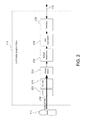
FIG. 2 is a block diagram for one embodiment of the capture subsystem of FIG. 1, in accordance with the present invention;
FIG. 3 is a block diagram for one embodiment of the control module of FIG. 1, in accordance with the present invention;
FIG. 4 is a block diagram for one embodiment of the memory of FIG. 3, in accordance with the present invention;
FIG. 5 is a diagram of one exemplary embodiment for capturing a defocused blur image, in accordance with the present invention;
FIG. 6 is a graph of an exemplary matching curve, in accordance with one embodiment of the present invention;
FIG. 7 is a graph of an exemplary Gaussian model of a blur image, in accordance with one embodiment of the present invention;
FIG. 8 is a graph of an exemplary pillbox model of a blur image, in accordance with one embodiment of the present invention;
FIGS. 9A-9C are a flowchart of method steps for performing a depth estimation procedure with pillbox blur images, in accordance with one embodiment of the present invention;
FIG. 10 is a diagram of two saturated pillbox images, in accordance with one exemplary embodiment of the present invention; and
FIG. 11 is a diagram illustrating a fillbox technique for the saturated pillbox images of FIG. 10, in accordance with one exemplary embodiment of the present invention.
DETAILED DESCRIPTION
The present invention relates to an improvement in image data analysis techniques. The following description is presented to enable one of ordinary skill in the art to make and use the invention and is provided in the context of a patent application and its requirements. Various modifications to the disclosed embodiments will be readily apparent to those skilled in the art, and the generic principles herein may be applied to other embodiments. Thus, the present invention is not intended to be limited to the embodiments shown, but is to be accorded the widest scope consistent with the principles and features described herein.
The present invention comprises a system and method for performing a depth estimation procedure by utilizing defocused pillbox images, and includes a camera device with a sensor device for capturing pillbox blur images of a photographic target. The camera utilizes a depth estimator for performing a Gaussianization procedure that transforms the pillbox blur images into corresponding Gaussian blur images. The Gaussianization procedure is performed by convolving the pillbox blur images with a Gaussianization kernel to generate the corresponding Gaussian blur images. The depth estimator then utilizes the Gaussian blur images for effectively performing the depth estimation procedure.
Referring now to FIG. 1, a block diagram for one embodiment of a camera device 110 is shown, in accordance with the present invention. In the FIG. 1 embodiment, camera device 110 may include, but is not limited to, a capture subsystem 114, a system bus 116, and a control module 118. In the FIG. 1 embodiment, capture subsystem 114 may be optically coupled to a photographic target 112, and may also be electrically coupled via system bus 116 to control module 118.
In alternate embodiments, camera device 110 may readily include various other components in addition to, or instead of, those components discussed in conjunction with the FIG. 1 embodiment. In addition, in certain embodiments, the present invention may alternately be embodied in any appropriate type of electronic device other than the camera device 110 of FIG. 1. For example, camera device 110 may alternately be implemented as an imaging device, a computer device, or a consumer electronics device.
In the FIG. 1 embodiment, once capture subsystem 114 of camera 110 is automatically focused on target 112, a camera user may request camera device 110 to capture image data corresponding to target 112. Control module 118 then may preferably instruct capture subsystem 114 via system bus 116 to capture image data representing target 112. The captured image data may then be transferred over system bus 116 to control module 118, which may responsively perform various processes and functions with the image data. System bus 116 may also bi-directionally pass various status and control signals between capture subsystem 114 and control module 118.
Referring now to FIG. 2, a block diagram for one embodiment of the FIG. 1 capture subsystem 114 is shown, in accordance with the present invention. In the FIG. 2 embodiment, capture subsystem 114 preferably comprises, but is not limited to, a shutter 218, a lens 220, an image sensor 224, red, green, and blue (R/G/B) amplifiers 228, an analog-to-digital (A/D) converter 230, and an interface 232. In alternate embodiments, capture subsystem 114 may readily include various other components in addition to, or instead of, those components discussed in conjunction with the FIG. 2 embodiment.
In the FIG. 2 embodiment, capture subsystem 114 may capture image data corresponding to target 112 via reflected light impacting image sensor 224 along optical path 236. Image sensor 224, which may preferably include a charged-coupled device (CCD), may responsively generate a set of image data representing the target 112. The image data may then be routed through amplifiers 228, A/D converter 230, and interface 232. From interface 232, the image data passes over system bus 116 to control module 118 for appropriate processing and storage. Other types of image capture sensors, such as CMOS or linear arrays are also contemplated for capturing image data in conjunction with the present invention. The utilization and functionality of camera 110 is further discussed below in conjunction with FIGS. 3-11.
Referring now to FIG. 3, a block diagram for one embodiment of the FIG. 1 control module 118 is shown, in accordance with the present invention. In the FIG. 3 embodiment, control module 118 preferably includes, but is not limited to, a viewfinder 308, a central processing unit (CPU) 344, a memory 346, and one or more input/output interface(s) (I/O) 348. Viewfinder 308, CPU 344, memory 346, and I/O 348 preferably are each coupled to, and communicate, via common system bus 116 that also communicates with capture subsystem 114. In alternate embodiments, control module 118 may readily include various other components in addition to, or instead of, those components discussed in conjunction with the FIG. 3 embodiment.
In the FIG. 3 embodiment, CPU 344 may be implemented to include any appropriate microprocessor device. Alternately, CPU 344 may be implemented using any other appropriate technology. For example, CPU 344 may be implemented to include certain application-specific integrated circuits (ASICs) or other appropriate electronic devices. Memory 346 may be implemented as one or more appropriate storage devices, including, but not limited to, read-only memory, random-access memory, and various types of non-volatile memory, such as floppy disc devices, hard disc devices, or flash memory. I/O 348 may provide one or more effective interfaces for facilitating bi-directional communications between camera device 110 and any external entity, including a system user or another electronic device. I/O 348 may be implemented using any appropriate input and/or output devices. The operation and utilization of control module 118 are further discussed below in conjunction with FIGS. 4 through 11.
Referring now to FIG. 4, a block diagram for one embodiment of the FIG. 3 memory 346 is shown, in accordance with the present invention. In the FIG. 4 embodiment, memory 346 may include, but is not limited to, a camera application 412, an operating system 414, a depth estimator 416, image data 418, estimation data 420, an auto-focus module 422, and miscellaneous information 424. In alternate embodiments, memory 346 may include various other components in addition to, or instead of, those components discussed in conjunction with the FIG. 4 embodiment.
In the FIG. 4 embodiment, camera application 412 may include program instructions that are preferably executed by CPU 344 (FIG. 3) to perform various functions and operations for camera device 110. The particular nature and functionality of camera application 412 preferably varies depending upon factors such as the type and particular use of the corresponding camera device 110.
In the FIG. 4 embodiment, operating system 414 preferably controls and coordinates low-level functionality of camera device 110. In accordance with the present invention, depth estimator 416 may control and coordinate a depth estimation procedure to facilitate automatic focus features in camera 110. In the FIG. 4 embodiment, image data 418 may include one or more images of a photographic target 112 captured by camera device 110. Estimation data 420 may include any types of information or data for performing a depth estimation procedure. In the FIG. 4 embodiment, auto-focus module 422 may utilize the results of the depth estimation procedure to perform an auto-focus procedure for camera device 110. Miscellaneous information 424 includes any other appropriate information for the operation of camera 110. Additional details regarding the operation of depth estimator 416 are further discussed below in conjunction with FIGS. 5-11.
Referring now to FIG. 5, a diagram of one exemplary embodiment for capturing a defocused blur image 518 is shown, in accordance with the present invention. The FIG. 5 embodiment is provided for purposes of illustration, and in alternate embodiments, the present invention may utilize various other configurations and elements to capture defocused blur images 518.
In the FIG. 5 embodiment, a sensor 224 of a camera 110 (see FIG. 2) may capture a defocused blur image 518 of a photographic target or scene 112 for performing a depth estimation procedure. The defocused blur image 518 may be created by adjusting lens 220 to a position other than the correct in-focus lens position that depends upon the relative positions of target 112, lens 220, and sensor 224.
In one embodiment, two different defocused blur images 518 may be compared to derive a depth estimation. A blur difference may be calculated for two blur images 518 that are one depth-of-field away from each other. A slope of a known matching curve and the blur difference can be utilized to determine the depth of a given target 112. The generation and utilization of defocused blur images for depth estimation are further discussed below in conjunction with FIGS. 6-11.
Referring now to FIG. 6, a graph of an exemplary matching curve 714 is shown, in accordance with one embodiment of the present invention. The FIG. 6 embodiment is presented for purposes of illustration, and in alternate embodiments, the present invention may be implemented to utilize matching curves with configurations and parameters in addition to, or instead of, certain of those configurations and parameters discussed in conjunction with the FIG. 6 embodiment.
In certain embodiments, a blur image1 and a more-defocused blur image2 may be captured, the sharper image1 may be convolved with a Gaussian kernel (for example, a 3×3 Gaussian matrix with small variance) to produce a convolved image1. The convolved image1 is compared to blur image2. This process is repeated until the two blur image match. The number of iterations may then be graphed against depth-of-field (or image numbers in increments of one DOF) to produce a blur matching curve that can be used to estimate the distance from any out-of-focus position to the in-focus position. Additional details regarding the foregoing depth estimation technique are further discussed in U.S. Pat. No. 8,045,046 to Li et al., which is hereby incorporated by reference.
Referring now to FIG. 7, a graph of an exemplary Gaussian model 718 of a blur image 518 (FIG. 5) is shown, in accordance with one embodiment of the present invention. The FIG. 7 embodiment is presented for purposes of illustration, and in alternate embodiments, the present invention may utilize Gaussian models with elements and configurations other than those discussed in conjunction with the FIG. 7 embodiment.
In the FIG. 7 embodiment, luminance is represented on a vertical axis and pixels are represented on a horizontal axis. In the FIG. 7 graph, Gaussian model 718 displays a typical bell-curve shape. However, not all blur images 518 are best represented by utilizing a Gaussian model 718. Depending upon image characteristics of a photographic target or scene, certain non-Gaussian models may be more effective. One example of a non-Gaussian model is further discussed below in conjunction with FIGS. 8-11.
Referring now to FIG. 8, a graph of an exemplary pillbox model of a blur image 518 shown, in accordance with one embodiment of the present invention. The FIG. 8 embodiment is presented for purposes of illustration, and in alternate embodiments, the present invention may utilize pillbox models with elements and configurations other than those discussed in conjunction with the FIG. 8 embodiment.
In the FIG. 8 embodiment, luminance is represented on a vertical axis and pixels are represented on a horizontal axis. In the FIG. 8 graph, pillbox model 818 displays a typical sharp-edged shape. Depending upon image characteristics of a photographic target or scene, certain non-Gaussian models, such as pillbox model 818, may be more effective. For example, a pillbox model 818 may be better for a dark night scene that includes a very bright light source such as a candle.
However, certain of the depth estimation techniques discussed above fail to perform satisfactorily when used in conjunction with pillbox blur images. In accordance with the present invention, a Gaussianization procedure is therefore utilized to advantageously transform the pillbox blur image into a Gaussian format that may then be successfully be utilized for depth estimation procedures, as discussed above.
The Gaussianization procedure may be performed in any effective manner. For example, a pillbox blur image may be convolved with a Gaussianization kernel to produce a Gaussianized blur image. The Gaussianization kernel may be implemented and utilized in any appropriate manner. For example, the Gaussianization kernel may be a Gaussian function or a more general blur function with a limited mean and variance.
In certain embodiments, the Gaussianization kernel may be implemented as a box function with a square matrix in which all matrix values are the same value, and the sum of all these matrix values equals 1. The Gaussianization kernel may also be implemented as a two-dimensional uniform box function which may be represented as a tensor product of two one-dimensional functions in accordance with the following formula:
f ( m , n ) = { 1 / ( 2 M + 1 ) ( 2 N + 1 ) , m M , n N 0 , elsewhere
where m and n are pixel coordinates, and where M and N are respective dimensions of the kernel matrix. In one alternate embodiment, multiple stages of Gaussianization may be utilized to improve efficiency. For example, a smaller gaussianization kernel may be utilized to perform the Gaussianization procedure in smaller segments. This technique may improve computational speed for images that do not require much Gaussianization. Additional details regarding the Gaussianization procedure are further discussed below in conjunction with FIGS. 9-11.
Referring now to FIGS. 9A-9C, a flowchart of method steps for performing a depth estimation procedure with pillbox images is shown, in accordance with one embodiment of the present invention. The FIG. 9 embodiment is presented for purposes of illustration, and in alternate embodiments, the present invention may readily utilize various steps and sequences other than those steps and sequences discussed in conjunction with the FIG. 9 embodiment.
In the FIG. 9A embodiment, in step 914, camera 110 captures a defocused pillbox image1. In step 918, the focus setting of camera 110 is changed. For example, in the FIG. 9A embodiment, the focus setting may be adjusted to decrease the focus of camera 110 by one depth-of-field. In step 922, camera 110 captures a defocused pillbox image2 that is more blurry (out of focus) than previously captured pillbox image1.
In step 926, a depth estimator 416 or other appropriate entity selects an appropriate kernel K for performing a convolution procedure. The kernel K may be configured in any appropriate manner. For example, in certain embodiments, kernel K may be configured as a 3-by-3 Gaussian kernel with a small variance. In step 926, depth estimator 416 also selects an appropriate Gaussianization kernel for performing a Gaussianization procedure in accordance with the present invention.
As discussed above, the Gaussianization kernel may be implemented and utilized in any appropriate manner. For example, the Gaussianization kernel may be a Gaussian function or a more general blur function with a limited mean and variance. In step 928, depth estimator 416 computes the matching error between image1 and image2, and in step 930, depth estimator 416 determines whether the images match. If the images match, then the FIG. 9 process may terminate. However, if the images do not match, then the FIG. 9A process advances to step 932 of FIG. 9B through connecting letter “A.”
In step 932, depth estimator 416 performs a convolution procedure to create a new current image1 that is equal to the immediately-preceding image1 convolved with the selected kernel K. In step 934, depth estimator 416 computes the matching error between the current image1 and image2. In step 938, depth estimator 416 determines whether current image1 and image2 match. If the two images do not match, then the FIG. 9 process returns to step 932 to perform additional iterations.
However, if image1 and image2 match in step 938, then in step 942, depth estimator 416 performs a Gaussianization procedure on both the current image1 and image2 by utilizing the previously-selected Gaussianization kernel to convert the non-Gaussian blur images into corresponding Gaussian blur images. In particular, depth estimator 416 performs a convolution procedure to create a new current image1 that is equal to the immediately-preceding image1 convolved with the selected Gaussianization kernel. In addition, depth estimator 416 performs a convolution procedure to create a new current image2 that is equal to the immediately-preceding image2 convolved with the selected Gaussianization kernel. In the FIG. 9B embodiment, the Gaussianization kernel may be implemented with a small variance value. The FIG. 9B process then advances to step 946 of FIG. 9C through connecting letter “B.”
In step 946, depth estimator 416 performs a convolution procedure to create a new current image1 that is equal to the immediately-preceding image1 convolved with the selected kernel K. In step 950, depth estimator 416 computes the matching error between the current image1 and current image2. In step 954, depth estimator 416 determines whether current image1 and current image2 match. If the two images do not match, then the FIG. 9 process returns to step 946 to perform additional iterations. However, if image1 and image2 match in step 938, then in step 958, depth estimator 416 determines how many convolutions have been performed in foregoing step 946. If there were non-zero convolutions, then the FIG. 9C process returns to step 942 of FIG. 9B through connecting letter “C” to perform one or more additional Gaussianization procedures. However, is there were zero convolutions, then the FIG. 9 process may terminate. The blur difference between image1 and image2 is then given by the total number of convolutions with kernel K performed at 932 and 946. The present invention therefore provides an improved system and method for performing a depth estimation procedure by utilizing pillbox blur images.
Referring now to FIG. 10, a diagram of two saturated pillbox images 1014 and 1018 is shown, in accordance with one embodiment of the present invention. The FIG. 10 embodiment is presented for purposes of illustration, and in alternate embodiments, the present invention may utilize pillbox images with elements and configurations other than those discussed in conjunction with the FIG. 10 embodiment.
In the FIG. 10 embodiment, waveforms for a first pillbox image 1014 (for example, image1 of FIG. 9) and a second pillbox image 1018 (for example, image2 of FIG. 9) are shown superimposed. Since image 1014 is more focused, its waveform shape is narrower and taller than the waveform of image 1018. However, like other types of blur images, pillbox blur images should preserve the same amount of energy/total luminance.
In the FIG. 10 embodiment, the pillbox images are clipped/saturated because they both exceed a saturation threshold level 1022. If the pillbox blur images are saturated/clipped, then there is a difference between the total luminance of two pictures. In general, blur matching techniques (such as the Gaussianization procedure discussed in FIG. 9) do not work well for saturated pillbox blur images because the total luminance is not preserved. Therefore, in accordance with certain embodiments of the present invention, a fillbox technique may be utilized before performing any blur matching techniques. One such fillbox embodiment is discussed below in conjunction with FIG. 11.
Referring now to FIG. 11, a diagram illustrating a fillbox technique for handling the FIG. 10 saturated pillbox images is shown, in accordance with one embodiment of the present invention. The FIG. 11 embodiment is presented for purposes of illustration, and in alternate embodiments, the present invention may utilize fillbox techniques with elements, steps, and configurations other than those discussed in conjunction with the FIG. 11 embodiment.
On the left side of the FIG. 11 diagram, the pillbox images 1018 and 1014(a) are clipped/saturated because they both exceed a saturation threshold level 1022. If the pillbox blur images are saturated/clipped, then there is a difference between the total luminance of two pictures. Since image 1014(a) is taller, it has more luminance removed by the saturation threshold 1022. As shown on the right side of the FIG. 11 diagram, the fillbox procedure may advantageously be utilized to equalize the respective luminance totals of images 1018 and 1014(a) by increasing the luminance of image 1014(a) by a luminance fill amount 1030 to thereby produce a new equalized image 1014(b).
In the FIG. 11 embodiment, the depth estimator 416 (FIG. 4) or other appropriate entity initially calculates the total luminance of the saturated pillbox in each picture 1014(a) and 1018. Depth estimator 416 determines the difference of the total luminance between the two pictures 1014(a) and 1018. Then for the pillbox blur image 1014(a) with smaller total luminance, depth estimator adds the average difference of the total luminance to each saturated pixel of the pillbox image 1014(a) to produce equalized image 1014(b). This fillbox technique may be characterized as filling the smaller pillbox image 1014(a) until the two images are equal in volume/total luminance. After completing the foregoing fillbox procedure, depth estimator 416 may treat the pillbox blur images 1014(b) and 1018 as non-saturated pillboxes, and may perform blur matching with the Gaussianization procedure discussed above in conjunction with FIG. 9.
The invention has been explained above with reference to certain embodiments. Other embodiments will be apparent to those skilled in the art in light of this disclosure. For example, the present invention may readily be implemented using configurations and techniques other than those described in the embodiments above. Additionally, the present invention may effectively be used in conjunction with systems other than those described above. Therefore, these and other variations upon the discussed embodiments are intended to be covered by the present invention, which is limited only by the appended claims.

Claims (20)

What is claimed is:
1. A system for performing a depth estimation procedure, comprising:
a sensor device for capturing pillbox blur images of a photographic target; and
a depth estimator for performing a Gaussianization procedure with a Gaussianization kernel that transforms said pillbox blur images into Gaussian blur images, said Gaussianization kernel being implemented as a tensor product of two one-dimensional functions, said depth estimator then utilizing said Gaussian blur images for performing said depth estimation procedure.
2. The system of claim 1 wherein said depth estimator performs said Gaussianization procedure by convolving said pillbox images with said Gaussianization kernel to produce said Gaussian blur images.
3. The system of claim 2 wherein said Gaussianization kernel is implemented as a box function with a square matrix in which all matrix values are an identical value, and the sum of all these matrix values equals 1.
4. A system for performing a depth estimation procedure, comprising:
a sensor device for capturing pillbox blur images of a photographic target; and
a depth estimator for performing a Gaussianization procedure that transforms said pillbox blur images into Gaussian blur images, said depth estimator then utilizing said Gaussian blur images for performing said depth estimation procedure, said depth estimator performing said Gaussianization procedure by convolving said pillbox images with a Gaussianization kernel to produce said Gaussian blur images, said Gaussianization kernel being implemented as a two-dimensional uniform box function which is represented as a tensor product of two one-dimensional functions in accordance with a formula:
f ( m , n ) = { 1 / ( 2 M + 1 ) ( 2 N + 1 ) , m M , n N 0 , elsewhere
where m and n are pixel coordinates, and where M and N are respective dimensions of a matrix of said Gaussianization kernel.
5. The system of claim 1 wherein said depth estimator determines that said pillbox blur images are clipped by a saturation threshold level, said depth estimator then performing a fillbox procedure to equalize energy totals for said pillbox blur images before performing said Gaussianization procedure.
6. The system of claim 5 wherein said depth estimator performs said fillbox procedure by initially calculating first total luminance of a first image and a second total luminance of a second image, said depth estimator determines a luminance difference between said first total luminance and said second total luminance.
7. The system of claim 6 wherein said depth estimator completes said fillbox procedure by adding said luminance difference to a smaller one of said pillbox blur images that has a smaller total luminance so that said energy totals of said first image and said second image are equalized.
8. The system of claim 1 wherein said sensor device and said depth generator are implemented in an electronic camera device that utilizes one or more depth values from said depth estimation procedure to perform an automatic focusing procedure.
9. The system of claim 8 wherein said sensor device captures an image 1 corresponding to a photographic target by utilizing a first defocused lens position, said camera device then being adjusted to a second defocused lens position that is different than said first defocused lens position, said sensor device capturing an image2 corresponding to said photographic target by utilizing said second defocused lens position, said second defocused lens position being less focused than said first defocused lens position.
10. The system of claim 9 wherein said depth estimator selects a kernel K and a Gaussianization kernel.
11. The system of claim 10 wherein said kernel K is implemented as a Gaussian 3-by-3 matrix with a small variance.
12. The system of claim 10 wherein said Gaussianization kernel is implemented as a box function with a square matrix in which all matrix values are an identical value, and the sum of all these matrix values equals 1.
13. The system of claim 10 wherein said depth estimator convolves said image1 with said kernel K in a first convolution procedure to produce a current convolved image1.
14. The system of claim 13 wherein said depth estimator compares said current convolved image1 with said image2 in a first blur image matching procedure, said depth estimator performing additional iterations of said convolution procedure until a first matching result is reached.
15. The system of claim 14 wherein said depth estimator utilizes a Gaussianization kernel to perform said Gaussianization procedure upon said first current convolved image1 and said image2 to produce a Gaussian image1 and a Gaussian image2.
16. The system of claim 15 wherein said depth estimator convolves said Gaussian image1 with said kernel K in a said second convolution procedure to produce a current convolved Gaussian image1.
17. The system of claim 16 wherein said depth estimator compares said current convolved Gaussian image1 with said Gaussian image2 in a second blur image matching procedure, said depth estimator performing additional iterations of said second convolution procedure until a second matching result is reached, said depth estimator generating a total iteration number based upon said additional iterations.
18. The system of claim 17 wherein said depth estimator utilizes said total iteration number to generate a matching curve for said depth estimation procedure, said depth estimator utilizes said matching curve to generate a depth value corresponding to said photographic target.
19. The system of claim 18 wherein said depth estimator performs a multi-stage Gaussianization procedure that processes segments of said pillbox blur images with a reduced-size Gaussianization kernel.
20. A method for performing a depth estimation procedure by performing the steps of:
providing a sensor device for capturing pillbox blur images of a photographic target; and
utilizing a depth estimator for performing a Gaussianization procedure with a Gaussianization kernel that transforms said pillbox blur images into Gaussian blur images, said Gaussianization kernel being implemented as a tensor product of two one-dimensional functions, said depth estimator then utilizing said Gaussian blur images for performing said depth estimation procedure.
US13/426,828 2011-12-01 2012-03-22 System and method for performing depth estimation utilizing defocused pillbox images Active 2033-01-16 US8929607B2 (en)

Priority Applications (7)

Application Number Priority Date Filing Date Title
US13/426,828 US8929607B2 (en) 2011-12-01 2012-03-22 System and method for performing depth estimation utilizing defocused pillbox images
CN201210479581.2A CN103136745B (en) 2011-12-01 2012-11-22 Utilization defocuses the system and method for pillbox image execution estimation of Depth
CA2796543A CA2796543C (en) 2011-12-01 2012-11-26 System and method for performing depth estimation utilizing defocused pillbox images
JP2012271753A JP5459523B2 (en) 2011-12-01 2012-11-26 System and method for depth estimation using defocused pillbox images
TW101144220A TWI557688B (en) 2011-12-01 2012-11-26 System and method for performing depth estimation utilizing defocused pillbox images
KR1020120136072A KR101437234B1 (en) 2011-12-01 2012-11-28 System and method for performing depth estimation utilizing defocused pillbox images
EP12195072.9A EP2600310B1 (en) 2011-12-01 2012-11-30 System and method for performing depth estimation utilizing defocused pillbox images

Applications Claiming Priority (2)

Application Number Priority Date Filing Date Title
US201161565790P 2011-12-01 2011-12-01
US13/426,828 US8929607B2 (en) 2011-12-01 2012-03-22 System and method for performing depth estimation utilizing defocused pillbox images

Publications (2)

Publication Number Publication Date
US20130142394A1 US20130142394A1 (en) 2013-06-06
US8929607B2 true US8929607B2 (en) 2015-01-06

Family

ID=47602841

Family Applications (1)

Application Number Title Priority Date Filing Date
US13/426,828 Active 2033-01-16 US8929607B2 (en) 2011-12-01 2012-03-22 System and method for performing depth estimation utilizing defocused pillbox images

Country Status (7)

Country Link
US (1) US8929607B2 (en)
EP (1) EP2600310B1 (en)
JP (1) JP5459523B2 (en)
KR (1) KR101437234B1 (en)
CN (1) CN103136745B (en)
CA (1) CA2796543C (en)
TW (1) TWI557688B (en)

Cited By (1)

* Cited by examiner, † Cited by third party
Publication number Priority date Publication date Assignee Title
US20180286066A1 (en) * 2015-09-18 2018-10-04 The Regents Of The University Of California Cameras and depth estimation of images acquired in a distorting medium

Families Citing this family (6)

* Cited by examiner, † Cited by third party
Publication number Priority date Publication date Assignee Title
US9066002B2 (en) 2012-08-29 2015-06-23 Sony Corporation System and method for utilizing enhanced scene detection in a depth estimation procedure
AU2013273843A1 (en) * 2013-12-23 2015-07-09 Canon Kabushiki Kaisha Motion blur compensation for depth from defocus
US9530214B2 (en) 2014-12-04 2016-12-27 Sony Corporation Image processing system with depth map determination based on iteration count of blur difference and method of operation thereof
WO2016154392A1 (en) * 2015-03-24 2016-09-29 University Of Florida Research Foundation, Inc. Optical privatizing device, system and method of use
CN111166322A (en) * 2020-01-17 2020-05-19 哈尔滨工业大学 Electrocardiosignal characteristic wave extraction method
CN113189634B (en) * 2021-03-02 2022-10-25 四川新先达测控技术有限公司 Gaussian-like forming method

Citations (15)

* Cited by examiner, † Cited by third party
Publication number Priority date Publication date Assignee Title
JP2001159159A (en) 1999-12-01 2001-06-12 Hitachi Ltd Water level control method and water supply system
US20030053667A1 (en) * 2001-05-17 2003-03-20 Nikolaos Paragios Variational approach for the segmentation of the left ventricle in MR cardiac images
US20070019883A1 (en) * 2005-07-19 2007-01-25 Wong Earl Q Method for creating a depth map for auto focus using an all-in-focus picture and two-dimensional scale space matching
US20070036427A1 (en) * 2005-08-15 2007-02-15 Makibi Nakamura Depth information for auto focus using two pictures and two-dimensional gaussian scale space theory
US20070297784A1 (en) * 2006-06-22 2007-12-27 Sony Corporation Method of and apparatus for generating a depth map utilized in autofocusing
US20090040342A1 (en) * 2006-02-14 2009-02-12 Fotonation Vision Limited Image Blurring
US20090268985A1 (en) * 2008-04-29 2009-10-29 Earl Quong Wong Reduced Hardware Implementation For A Two-Picture Depth Map Algorithm
US20100008574A1 (en) 2007-02-28 2010-01-14 Nikon Corporation Image processing method
US20100033618A1 (en) * 2006-03-16 2010-02-11 Earl Quong Wong Simple method for calculating camera defocus from an image scene
US20100080482A1 (en) * 2008-09-30 2010-04-01 Earl Quong Wong Fast Camera Auto-Focus
US20100194971A1 (en) 2009-01-30 2010-08-05 Pingshan Li Two-dimensional polynomial model for depth estimation based on two-picture matching
WO2011084279A2 (en) 2009-12-16 2011-07-14 Sony Electronics Inc. Algorithms for estimating precise and relative object distances in a scene
US8045046B1 (en) * 2010-04-13 2011-10-25 Sony Corporation Four-dimensional polynomial model for depth estimation based on two-picture matching
US20110279699A1 (en) * 2010-05-17 2011-11-17 Sony Corporation Image processing apparatus, image processing method, and program
US20120033094A1 (en) * 2010-02-12 2012-02-09 Panasonic Corporation Imaging device and method, and image processing method for imaging device

Family Cites Families (3)

* Cited by examiner, † Cited by third party
Publication number Priority date Publication date Assignee Title
JP3481631B2 (en) * 1995-06-07 2003-12-22 ザ トラスティース オブ コロンビア ユニヴァーシティー イン ザ シティー オブ ニューヨーク Apparatus and method for determining a three-dimensional shape of an object using relative blur in an image due to active illumination and defocus
JP4524717B2 (en) * 2008-06-13 2010-08-18 富士フイルム株式会社 Image processing apparatus, imaging apparatus, image processing method, and program
JP5468404B2 (en) * 2010-02-02 2014-04-09 パナソニック株式会社 Imaging apparatus and imaging method, and image processing method for the imaging apparatus

Patent Citations (16)

* Cited by examiner, † Cited by third party
Publication number Priority date Publication date Assignee Title
JP2001159159A (en) 1999-12-01 2001-06-12 Hitachi Ltd Water level control method and water supply system
US20030053667A1 (en) * 2001-05-17 2003-03-20 Nikolaos Paragios Variational approach for the segmentation of the left ventricle in MR cardiac images
US20070019883A1 (en) * 2005-07-19 2007-01-25 Wong Earl Q Method for creating a depth map for auto focus using an all-in-focus picture and two-dimensional scale space matching
US20070036427A1 (en) * 2005-08-15 2007-02-15 Makibi Nakamura Depth information for auto focus using two pictures and two-dimensional gaussian scale space theory
US7929801B2 (en) 2005-08-15 2011-04-19 Sony Corporation Depth information for auto focus using two pictures and two-dimensional Gaussian scale space theory
US20090040342A1 (en) * 2006-02-14 2009-02-12 Fotonation Vision Limited Image Blurring
US20100033618A1 (en) * 2006-03-16 2010-02-11 Earl Quong Wong Simple method for calculating camera defocus from an image scene
US20070297784A1 (en) * 2006-06-22 2007-12-27 Sony Corporation Method of and apparatus for generating a depth map utilized in autofocusing
US20100008574A1 (en) 2007-02-28 2010-01-14 Nikon Corporation Image processing method
US20090268985A1 (en) * 2008-04-29 2009-10-29 Earl Quong Wong Reduced Hardware Implementation For A Two-Picture Depth Map Algorithm
US20100080482A1 (en) * 2008-09-30 2010-04-01 Earl Quong Wong Fast Camera Auto-Focus
US20100194971A1 (en) 2009-01-30 2010-08-05 Pingshan Li Two-dimensional polynomial model for depth estimation based on two-picture matching
WO2011084279A2 (en) 2009-12-16 2011-07-14 Sony Electronics Inc. Algorithms for estimating precise and relative object distances in a scene
US20120033094A1 (en) * 2010-02-12 2012-02-09 Panasonic Corporation Imaging device and method, and image processing method for imaging device
US8045046B1 (en) * 2010-04-13 2011-10-25 Sony Corporation Four-dimensional polynomial model for depth estimation based on two-picture matching
US20110279699A1 (en) * 2010-05-17 2011-11-17 Sony Corporation Image processing apparatus, image processing method, and program

Non-Patent Citations (5)

* Cited by examiner, † Cited by third party
Title
Imaging Solution, (Online) Sep. 15, 2008, URL: http://imagingsolution.blog107.fc2.com/blog-entry-88.html, pp. 1-3.
N. Intrator, N. Neretti, T. Nguyen, Y. Chen, Q. Huynh, R. Coifman, I. Cohen, An Integrated Approach to Pattern Recognition, Brown University, Boston University, Navsea, Yale University, Office of Naval Research, www.physics.brown.edu/physics/userpages/faculty/Nathan-Intrator/darpa/index.html, Aug./Sep. 2000, 1-74 pgs.
N. Intrator, N. Neretti, T. Nguyen, Y. Chen, Q. Huynh, R. Coifman, I. Cohen, An Integrated Approach to Pattern Recognition, Brown University, Boston University, Navsea, Yale University, Office of Naval Research, www.physics.brown.edu/physics/userpages/faculty/Nathan—Intrator/darpa/index.html, Aug./Sep. 2000, 1-74 pgs.
Yasuyuki Suga, Image Processing Program Using TEO Library, A Beginner's Guide, http://www.iim.ics.tut.ac.jp/~sugaya/books/TeoProgrammingGuide/ref/pg-0073.pdf, Mar. 22, 2006, p. 64.
Yasuyuki Suga, Image Processing Program Using TEO Library, A Beginner's Guide, http://www.iim.ics.tut.ac.jp/˜sugaya/books/TeoProgrammingGuide/ref/pg—0073.pdf, Mar. 22, 2006, p. 64.

Cited By (2)

* Cited by examiner, † Cited by third party
Publication number Priority date Publication date Assignee Title
US20180286066A1 (en) * 2015-09-18 2018-10-04 The Regents Of The University Of California Cameras and depth estimation of images acquired in a distorting medium
US11024047B2 (en) * 2015-09-18 2021-06-01 The Regents Of The University Of California Cameras and depth estimation of images acquired in a distorting medium

Also Published As

Publication number Publication date
JP5459523B2 (en) 2014-04-02
EP2600310A3 (en) 2017-01-25
KR20130061635A (en) 2013-06-11
CA2796543C (en) 2015-06-23
CA2796543A1 (en) 2013-06-01
JP2013117967A (en) 2013-06-13
EP2600310A2 (en) 2013-06-05
TWI557688B (en) 2016-11-11
CN103136745A (en) 2013-06-05
TW201337838A (en) 2013-09-16
EP2600310B1 (en) 2018-07-04
US20130142394A1 (en) 2013-06-06
CN103136745B (en) 2016-05-18
KR101437234B1 (en) 2014-09-02

Similar Documents

Publication Publication Date Title
US8929607B2 (en) System and method for performing depth estimation utilizing defocused pillbox images
US9066002B2 (en) System and method for utilizing enhanced scene detection in a depth estimation procedure
US9161010B2 (en) System and method for generating robust depth maps utilizing a multi-resolution procedure
KR101429371B1 (en) Algorithms for estimating precise and relative object distances in a scene
US10269130B2 (en) Methods and apparatus for control of light field capture object distance adjustment range via adjusting bending degree of sensor imaging zone
US9208570B2 (en) System and method for performing depth estimation by utilizing an adaptive kernel
US20150086127A1 (en) Method and image capturing device for generating artificially defocused blurred image
US9723197B2 (en) Depth estimation from image defocus using multiple resolution Gaussian difference
JP6711396B2 (en) Image processing device, imaging device, image processing method, and program
US9262833B2 (en) Methodology for performing depth estimation with defocused images under extreme lighting conditions
US9020280B2 (en) System and method for evaluating focus direction under various lighting conditions
CN102708559B (en) Blur difference estimation using multi-kernel convolution

Legal Events

Date Code Title Description
AS Assignment

Owner name: SONY CORPORATION, JAPAN

Free format text: ASSIGNMENT OF ASSIGNORS INTEREST;ASSIGNORS:LI, PINGSHAN;MIYAGI, KENSUKE;CIUREA, FLORIAN;AND OTHERS;SIGNING DATES FROM 20120320 TO 20120321;REEL/FRAME:028132/0218

FEPP Fee payment procedure

Free format text: PAYOR NUMBER ASSIGNED (ORIGINAL EVENT CODE: ASPN); ENTITY STATUS OF PATENT OWNER: LARGE ENTITY

STCF Information on status: patent grant

Free format text: PATENTED CASE

MAFP Maintenance fee payment

Free format text: PAYMENT OF MAINTENANCE FEE, 4TH YEAR, LARGE ENTITY (ORIGINAL EVENT CODE: M1551)

Year of fee payment: 4

MAFP Maintenance fee payment

Free format text: PAYMENT OF MAINTENANCE FEE, 8TH YEAR, LARGE ENTITY (ORIGINAL EVENT CODE: M1552); ENTITY STATUS OF PATENT OWNER: LARGE ENTITY

Year of fee payment: 8