US892902A - Pattern mechanism for straight-knitting machines. - Google Patents
Pattern mechanism for straight-knitting machines. Download PDFInfo
- Publication number
- US892902A US892902A US38237707A US1907382377A US892902A US 892902 A US892902 A US 892902A US 38237707 A US38237707 A US 38237707A US 1907382377 A US1907382377 A US 1907382377A US 892902 A US892902 A US 892902A
- Authority
- US
- United States
- Prior art keywords
- cam
- needle plate
- lever
- needle
- needles
- Prior art date
- Legal status (The legal status is an assumption and is not a legal conclusion. Google has not performed a legal analysis and makes no representation as to the accuracy of the status listed.)
- Expired - Lifetime
Links
Images


Classifications
-
- D—TEXTILES; PAPER
- D04—BRAIDING; LACE-MAKING; KNITTING; TRIMMINGS; NON-WOVEN FABRICS
- D04B—KNITTING
- D04B15/00—Details of, or auxiliary devices incorporated in, weft knitting machines, restricted to machines of this kind
- D04B15/10—Needle beds
- D04B15/12—Shogging devices therefor
Definitions
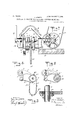
- Fig. 4 is fa sectional sideelevation of the improveni'ent on the'li-ne 44 of Fig. 2
- Fig. 5 is a sirnil ai view of the same on the line 5-5 of Fig? Fi g. G i sian enlarged sectional plan view'ofone ofithe pawls, and the eccentric and shaft imparting motion to the pawl;
- - -.-'8 isa' face view of the cam lever and the means for adjustin the throw thereof, parts beingshownin sec ion;
- Fig. 9 is'an enlarged face view'of one of the interchangeable cams for sknitting.fabrics differently ornamented;
- .Fig. 10 ⁇ is-a diagrammatic view showing the different positions of; the movable needle plate for succeedin'g rows of stitches;
- Fig. 11 isa-siniilarlview of the same and showing different positions of the needle. plate;
- the needle plate G is con- ASSIGNOR OF'ONE-THIRD TO THEODO R1 5 Hhlihldili, OF -NEW'YORK, N. Y.
- the knitting machine is mounted on'a suitably constructed frame A on which reciprocates the carriageB connected by, a pitman C with the crank arm D of a crank shaft D extending transversely and journaled on the main frame A.
- T he crank shaft'B is connected by the bevel gear wheels E and E with the main driving shaftF, extending longitudinally and journ'aled in suitable -bearings on the main frame A.
- On the main driving shaft F are arranged fastand loose pulleys F connected by a belt F with other 'inaclnnery, for imparting a continuous rotai'y niotionto the shafts? aiid'l), so that the crank arm D and thepitnian C impart a reciprocating motion to thclcarriage-B.
- crank arm D is provided with a handle D for conveniently turning the crank arm D by hand, to permit theoperator to shift thecarriage B when starting the machine or in case of a break or the like;
- the needle platesG, G are inclined toward each other and are provided withsuit- .able guideways for the two rows of needles H and H- to which the yarn or thread is' passed from the oscillating yarncarrier'l eX- tending between the usual guide. arms B,
- the needle plate G is fixedon one side of the main frameA, whilethe needle plate G is mounted to-shde lengthwise on the other side of the main frame, and this slid-' able needle plate G receives an intermittent reciprocating motion to' var the rows of stitches, one relative to the other according to a predetermined design for'inaking For the nected by a pitman J with the upper eiid'of a lever K, carrying at its lower end a friction roller K engaging a cam groove L versely and journaledin suitablebearings on the main frame A.
- the said lever K is provided at or near the middle with a vertical elongated slot K into which fits a block K mounted to turn on a bolt K adjustably secured in a bearing A of the main frame A (see Figs. 7 and 8).
- the bearing A is provided with a vertical elongated slot A for the passage 6f the bolt stud K*, to allow of moving the bolt stud K up or down, to vary the throw of the lever K according to the number of needles per inch in the needle plates G and G used at a time'in the machine.
- the bolt K after being adjusted up or down is locked in place on the bearing A by its nut K and by adjusting screws K screwing in the top and bottom of the hearing A.
- a pivot pin J for connecting the pitnian J with the lever K is adjustably secured in an elongated slot K formed in the upper end of the lever K, as plainly indicated in Figs. 7 and 8.
- a ratchet wheel 0 of a width suflicient to accommodate two pawls P and Q, used for imparting a turning motion to the ratchet wheel 0 and consequently to the cam wheel L, so that the latter imparts a swinging mo tion to the lever K, which by-the pitman J shifts the needle plate G in a longitudinal direction, and at the time the carriage B is at the end of either its forward or backward stroke.
- the pawls P and Q are actuated by eccentrics P and Q secured to the crank shaft D, and arranged in diametrical positions, one relative-to the other, so as to actuatethe pawls P and Q in opposite directions, that is, when the pawl P is on its ac tive stroke and turns the ratchet wheel 0, then the pawl Q is on the return or inactive and vice versa.
- Accidental return movement of the ratchet wheel O is prevented by a spring dog 0 (see Fig. 5").
- the'pawl Q is periodically thrown out of engagement with the ratchet wheel 0, so that only the pawl P remains active, and the needle plate G is shifted only when thecarriage B is at the end of its stroke.
- the free end of the pawl Q is rovided with a transversely extending pin Q reaching over onto the top of a sprocket chain R hung on a sprocket wheel R, mounted to rotate loosely on the shaft X, and on the said sprocket wheel R is secured or formed a ratchet wheel S engaged by a pawl T mounted on an eccentric T attached to the crank shaft D, so that when the machine is running the crank shaft D and the eccentric T impart motion to the pawl T to intermittently turn the ratchet quently the latter is only intermittently,
- thenedle plate G can be shifted alternately forward and backward at the end of each forward and backward stroke of the carriage B, or at alternate strokes of the carriage or at any number of strokes and in any desired sequence, as will be readily understood by reference to Figs. 10, 11, 13 and 14, which show some of the different positions into which the needle plate G can be shifted by the use of diiferent cams L and chains R.
- the needle plate can be intermittently shifted in vari-- ous Ways, for instance, stepwise, first in one Now by varying the links needle plates, of which one is movable inthe direction of its length, needles mounted on "the" needle plates, a reciprocating carriage for actuating the needles, and a shifting mechable needle plate, a cam for actuating the said.
- LA knitting machine provided with needle plates, of which one is movable in the d rection of tslength, needles mounted on the needle ila'teaa reciprocating carriage for actuating t e needles,- and ,a shifting mechanism for the said movable needle plate to Zvariably shift the latter whenever the ear v.riage reaches the end of its stroke, and having a cam, means for intermittently rotating the -cam,-and means for retarding the speed of the cam at. predetermined intervals.
- a knitting machine provided with anism for the said movable needle plate comprising 'a lever mounted with the said movableneedle plate, a cam for imparting niotion to the said lever, actuating means 'for turning the'said cam, and means for varying the action of the said actuating means.
- a knitting machine provided with needle-plates, of which one is movable in the direction of its length, needles mounted on the needle plates, a reciprocating carriage for actuating the needles, and a shifting mechan sm for the said movable needle plate, comprising a lever mounted with the said movable needle plate, a cam for imparting motion to the said lever, actuating means for turning the said cam, and a chain mechanism for controlling the said actuating means.
- a knitting machine provided with needle plates, of which one is movable in the direction of its length, needles mounted on the needle plates, a reciprocating carriage for actuating the needles, and a shifting mechanism tor the said movable needle plate, comprising a lever connected with the said movlever, a double pawl and ratchet mechanism for turning the said cam, and a controlling device for; throwing one of the pawls of the said mechanism in and out. of gear.
- a knitting machine provided with needle plates, of which one is movable in the direction of its length, needles mounted on the needle plates, a reciprocating carriage [or actuating. the needles, and a shifting mechanism for the said movable needle plate com- A rising a lever connected with the said mov able needle plate, a cam for actuating the said. lever, a double pawl and ratchet mechanism for turning the said cam, and a coin trolling device having an intermittently rotating sprocket wheel, and a chain passing ver the said sprocket wheel, the chain having irojections for throwing one oi the pawls of t ie said mechanism in and out of gear.
- a knitting machine provided with a shifting device fora needle plate comprising a lever connected with the said needle plate, a cam engaging the said lever, a ratchet wheel rotating with the said cam, a pair of pawls ior turning the said ratchet wheel, and meanslbr throwing one ol the said pawls periodically in and out of gear.
- a knitting machine provided with a shifting device fora needle plate comprising a lever connected with the said needle plate, a cam engaging the said lever, a ratchet. wheel rotating with the said cam, a pair of pawls for turning the said ratchet wheel, one of the pawlsl'iavii'ig a pin, meansfor actuating the pawls, a sprocket wheel, means for intermittently turning the said sprocket wheel, and a sprocket chain on thesaid sprocketwhecl and having spaced projections for en gagenicnt with the said pin to throw the said pin pawl in and out of gear with the said ratchet wheel.
- a knitting machine provided with needle plates, of which one is movable in the direction oi: its length, needles mounted on the needle plates, a reciprocating carriage l'or actuating the needles, and a shifting mechanism for the said movable needle plate, comprising a lever connected with the said movable needle late, a cam for imparting motion to the saii. lever, actuatingmeans for turning the said cam, controlling means for controlling the said actuating means, and means for adjusting the fulcrum oi' the said lever to vary the throw olithe latter.
- a knitting machine providedwith a movable needle plate carrying a row of needles, a lever connected with the said needle plate, means for actuating the said lever, and
Landscapes
- Engineering & Computer Science (AREA)
- Textile Engineering (AREA)
- Knitting Machines (AREA)
Description
No. 892,902. PATENTED JULY '7, 1908.
' J. SGHUTZ.
PATTERN MECHANISM FOR STRAIGHT KNITTING MACHINES.
APPLICATION FILED JULY 6. 1907.
6 SHEETS-SHEET 1.
WITNESSES N INVENTOH fi/Nz 1.70/2 a f z B Y fl //1 M m @0.
,4 7'7'0HNEYS No. 892,902. PATENTED JULY 7, 1908. J. SGHUTZ.
PATTERN MECHANISM FOR STRAIGHT KNITTING MACHINES.
APPLICATION FILED JULY 5.1907.
5 SHBETS-SHEET 2 Q W/T/VESSES m /NVENTO/? p j 7Z YCJZZZZZ By WM #61; 1% ATTORNEYS No. 892,902. PATENTED JULY 7, 1908. J. SOHUTZ.
PATTERN MECHANISM FOR STRAIGHT KNITTING MACHINES.
APPLICATION FILED JULY 5. 1007.
5 SHEETS-SHEET 3.
WITNESSES UVVEN r05 A TTORN E 78 PATTERN MECHANISM, FOR STRAIGHT KNITTING MACHINES.
APPLICATION FILED JULY 5.1.907.
5 SHEETSSHEET 4.
' WITNESSES INVENTO firz ,d c/zaiz By 271% ATTORNEYS No.-892,902. PATENTED JULY 7, 1908.
' J. SGHUTZ.
PATTERN MECHANISM FOR STRAIGHT KNITTING MACHINES.
APPLICATION FILED JULY 5 1907 s 8HEETS-8HEI JT a.
INVENTOH Jfii? Jail: 52
ATTORNEYS JQHiiTlSCH UIZ; oF- NEwvoRK; Y.,
' ToIaZL-whom it ma'y conce'rnf.
t U i- E STATES PAT NT o -Fion ii i " -";'B.e-it knoWnthat I, JOHN SoHUTz, a citizefi of-tli eUnited States, and a resident of the I city :Of'NeW YOrk, borough of Brooklvn in- *e'iithecoiintyzof Kings andState of New York,
' have "invented :a new I and "Improved Pattern fMechanisrn' -foir Straight-Knitting Machines,
of 'which the followingis afull, clear, and e);- LaetdQScri ti n L having'twostraight rows'of needles arranged on oppos'ite-sides; and'its object is to provide 'a-znewand improved knitting machine ar ranged to automatically vary the relation of ,it'
"successive rows' of stitches according to a predetermined design, for producing a fabric ;of a' highly ornamental character.
The -invention consists of nov'el features f andparts 'and combinations of the same, which will be 'more fully described hereinafter and then-pointed out in the claims. j A practical'ern'bodiment of the invention is representedin the accompanying drawings forminga part of this specification, in which ending parts in all the views.
- igurel is aside elevation of the improvement;i -Fig. 2 isla plan View of the same;
an endelevation of the same; Fig. 4 is fa sectional sideelevation of the improveni'ent on the'li-ne 44 of Fig. 2; Fig. 5 is a sirnil ai view of the same on the line 5-5 of Fig? Fi g. G i sian enlarged sectional plan view'ofone ofithe pawls, and the eccentric and shaft imparting motion to the pawl;
3-7; isgan enlarged transverse section of the improvement on the l ne 7 7 of Fig. 2; Fig.
- -.-'8 isa' face view of the cam lever and the means for adjustin the throw thereof, parts beingshownin sec ion; Fig. 9 is'an enlarged face view'of one of the interchangeable cams for sknitting.fabrics differently ornamented; .Fig. 10} is-a diagrammatic view showing the different positions of; the movable needle plate for succeedin'g rows of stitches; Fig. 11 isa-siniilarlview of the same and showing different positions of the needle. plate; Fig. izianen l' -rge l face view of afabric knitted 1 byft l c us of the change arrangement shown Specification of Letters Patent.
Application filed July 5, 1907. Serial No. 382,377.
.he' inventionrelatesto knitting machines similar characters of reference indicate cor-J 'shogged or crossed stitch work.
purpose mentioned the needle plate G is con- ASSIGNOR OF'ONE-THIRD TO THEODO R1 5 Hhlihldili, OF -NEW'YORK, N. Y.
iiir'rnnn ivmcHANisM FOB srnaiennimrr'rme iviaoi mns ratente i'nu 7, 1908.
various pdsitions for knitting a fabric of another design. i
,The knitting machine is mounted on'a suitably constructed frame A on which reciprocates the carriageB connected by, a pitman C with the crank arm D of a crank shaft D extending transversely and journaled on the main frame A. T he crank shaft'B is connected by the bevel gear wheels E and E with the main driving shaftF, extending longitudinally and journ'aled in suitable -bearings on the main frame A. On the main driving shaft F are arranged fastand loose pulleys F connected by a belt F with other 'inaclnnery, for imparting a continuous rotai'y niotionto the shafts? aiid'l), so that the crank arm D and thepitnian C impart a reciprocating motion to thclcarriage-B.
The crank arm D is provided with a handle D for conveniently turning the crank arm D by hand, to permit theoperator to shift thecarriage B when starting the machine or in case of a break or the like;
The needle platesG, G are inclined toward each other and are provided withsuit- .able guideways for the two rows of needles H and H- to which the yarn or thread is' passed from the oscillating yarncarrier'l eX- tending between the usual guide. arms B,
B secured to the carriage B. 'lhe'needles H, H are actuated by the usual needle actuating devices held on the carriage B and moving with the same, "so that further descriptionof the same is not deemed necessary. The needle plate G is fixedon one side of the main frameA, whilethe needle plate G is mounted to-shde lengthwise on the other side of the main frame, and this slid-' able needle plate G receives an intermittent reciprocating motion to' var the rows of stitches, one relative to the other according to a predetermined design for'inaking For the nected by a pitman J with the upper eiid'of a lever K, carrying at its lower end a friction roller K engaging a cam groove L versely and journaledin suitablebearings on the main frame A.
In order to permit of using the same cam stroke and glides over the ratchet wheel 0' 'L on one machine when using the interchangable plates G, G having more or less needles to the inch, it is necessary to adjust the throw of the lever K, and for this purpose the said lever K is provided at or near the middle with a vertical elongated slot K into which fits a block K mounted to turn on a bolt K adjustably secured in a bearing A of the main frame A (see Figs. 7 and 8). The bearing A is provided with a vertical elongated slot A for the passage 6f the bolt stud K*, to allow of moving the bolt stud K up or down, to vary the throw of the lever K according to the number of needles per inch in the needle plates G and G used at a time'in the machine. The bolt K after being adjusted up or down is locked in place on the bearing A by its nut K and by adjusting screws K screwing in the top and bottom of the hearing A. A pivot pin J for connecting the pitnian J with the lever K is adjustably secured in an elongated slot K formed in the upper end of the lever K, as plainly indicated in Figs. 7 and 8.
On the cam wheel L is secured or formed a ratchet wheel 0 of a width suflicient to accommodate two pawls P and Q, used for imparting a turning motion to the ratchet wheel 0 and consequently to the cam wheel L, so that the latter imparts a swinging mo tion to the lever K, which by-the pitman J shifts the needle plate G in a longitudinal direction, and at the time the carriage B is at the end of either its forward or backward stroke. The pawls P and Q are actuated by eccentrics P and Q secured to the crank shaft D, and arranged in diametrical positions, one relative-to the other, so as to actuatethe pawls P and Q in opposite directions, that is, when the pawl P is on its ac tive stroke and turns the ratchet wheel 0, then the pawl Q is on the return or inactive and vice versa. Accidental return movement of the ratchet wheel O is prevented by a spring dog 0 (see Fig. 5").
In order to vary the shifting of the needle plate G by the pawls P and Q, the'pawl Q is periodically thrown out of engagement with the ratchet wheel 0, so that only the pawl P remains active, and the needle plate G is shifted only when thecarriage B is at the end of its stroke. For the purpose men tioned the following device is provided: The free end of the pawl Q is rovided with a transversely extending pin Q reaching over onto the top of a sprocket chain R hung on a sprocket wheel R, mounted to rotate loosely on the shaft X, and on the said sprocket wheel R is secured or formed a ratchet wheel S engaged by a pawl T mounted on an eccentric T attached to the crank shaft D, so that when the machine is running the crank shaft D and the eccentric T impart motion to the pawl T to intermittently turn the ratchet quently the latter is only intermittently,
turned by the pawl P, to shift the needle plate G onlyat the end of the forward stroke of the carriage B. As the sprocket chain R receives an intermittent traveling motion by the pawl P, itisevident that the projection R in engagement with the pin Q at the time,.
finally leaves the latter, so that the pawl Q swings downward back into engagement with the ratchet wheel 0, to again assume its function, that is, to turn the ratchet-wheel Q and the cam L for shifting the needle plate G at the time the carriage B is at the rear end of its stroke. in the sprocket chain ,R carrying the projections R that is, by spacing the projections R nearer to or farther apart, it is-evident that the pawl Q is rendered inactive at different periods, to vary the design of the fabric. If desired the pawl Q' may be completely thrown out of engagement with the ratchet wheel 0 by the operator for a certain kind of work, so that only the pawl P re-1 mains .active. Return movement of the ratchet wheel S .is prevented by a spring dog S (see Fig. 4.) By using different sprocket chains R ,having projections R nearertoward or farther from each other, a
great variety of differently ornamented fab rics can be knitted on the machine, and in a like manner the designs can .be'varied by using cams L having their cam grooves L of various forms, as will be readily understood by comparison of Figs. 1 to 9.
It is understood that variations in the sprocket chains R and earns L produce a different shifting of the needle plate at different periods and different distances, and hence a corresponding variation in the successive rows of stitches in the fabric is produced.
Thus thenedle plate G can be shifted alternately forward and backward at the end of each forward and backward stroke of the carriage B, or at alternate strokes of the carriage or at any number of strokes and in any desired sequence, as will be readily understood by reference to Figs. 10, 11, 13 and 14, which show some of the different positions into which the needle plate G can be shifted by the use of diiferent cams L and chains R. The throw given to the needle late G at a time corres onds to the distance etween adjacent nee les, but the needle plate can be intermittently shifted in vari-- ous Ways, for instance, stepwise, first in one Now by varying the links needle plates, of which one is movable inthe direction of its length, needles mounted on "the" needle plates, a reciprocating carriage for actuating the needles, and a shifting mechable needle plate, a cam for actuating the said.
-stitchesi ceases (seeliigsil3 and 14), the needle plate remaining stationary in any one cl" its shifted positions for any desired mmiber of rows ot described my invention, I
I QC aim asnew and desire to secure by Letters Patent? LA knitting machine provided with needle plates, of which one is movable in the d rection of tslength, needles mounted on the needle ila'teaa reciprocating carriage for actuating t e needles,- and ,a shifting mechanism for the said movable needle plate to Zvariably shift the latter whenever the ear v.riage reaches the end of its stroke, and having a cam, means for intermittently rotating the -cam,-and means for retarding the speed of the cam at. predetermined intervals.
'2. A knitting machine provided with anism for the said movable needle plate comprising 'a lever mounted with the said movableneedle plate, a cam for imparting niotion to the said lever, actuating means 'for turning the'said cam, and means for varying the action of the said actuating means.
' 3. A knitting machine provided with needle-plates, of which one is movable in the direction of its length, needles mounted on the needle plates, a reciprocating carriage for actuating the needles, and a shifting mechan sm for the said movable needle plate, comprising a lever mounted with the said movable needle plate, a cam for imparting motion to the said lever, actuating means for turning the said cam, and a chain mechanism for controlling the said actuating means.
4. A knitting machine provided with needle plates, of which one is movable in the direction of its length, needles mounted on the needle plates, a reciprocating carriage for actuating the needles, and a shifting mechanism tor the said movable needle plate, comprising a lever connected with the said movlever, a double pawl and ratchet mechanism for turning the said cam, and a controlling device for; throwing one of the pawls of the said mechanism in and out. of gear.
5. A knitting machine provided with needle plates, of which one is movable in the direction of its length, needles mounted on the needle plates, a reciprocating carriage [or actuating. the needles, and a shifting mechanism for the said movable needle plate com- A rising a lever connected with the said mov able needle plate, a cam for actuating the said. lever, a double pawl and ratchet mechanism for turning the said cam, and a coin trolling device having an intermittently rotating sprocket wheel, and a chain passing ver the said sprocket wheel, the chain having irojections for throwing one oi the pawls of t ie said mechanism in and out of gear.
(5. A knitting machine provided with a shifting device fora needle plate comprising a lever connected with the said needle plate, a cam engaging the said lever, a ratchet wheel rotating with the said cam, a pair of pawls ior turning the said ratchet wheel, and meanslbr throwing one ol the said pawls periodically in and out of gear. i
'7. A knitting machine provided with a shifting device fora needle plate comprising a lever connected with the said needle plate, a cam engaging the said lever, a ratchet. wheel rotating with the said cam, a pair of pawls for turning the said ratchet wheel, one of the pawlsl'iavii'ig a pin, meansfor actuating the pawls, a sprocket wheel, means for intermittently turning the said sprocket wheel, and a sprocket chain on thesaid sprocketwhecl and having spaced projections for en gagenicnt with the said pin to throw the said pin pawl in and out of gear with the said ratchet wheel.
8. A knitting machine provided with needle plates, of which one is movable in the direction oi: its length, needles mounted on the needle plates, a reciprocating carriage l'or actuating the needles, and a shifting mechanism for the said movable needle plate, comprising a lever connected with the said movable needle late, a cam for imparting motion to the saii. lever, actuatingmeans for turning the said cam, controlling means for controlling the said actuating means, and means for adjusting the fulcrum oi' the said lever to vary the throw olithe latter.
5). A knitting machine providedwith a movable needle plate carrying a row of needles, a lever connected with the said needle plate, means for actuating the said lever, and
JOHN 'scHUTZ;
Witnesses. V
lluno G. llov'rnn, Jenn P. DAVIS.
Priority Applications (1)
| Application Number | Priority Date | Filing Date | Title |
|---|---|---|---|
| US38237707A US892902A (en) | 1907-07-05 | 1907-07-05 | Pattern mechanism for straight-knitting machines. |
Applications Claiming Priority (1)
| Application Number | Priority Date | Filing Date | Title |
|---|---|---|---|
| US38237707A US892902A (en) | 1907-07-05 | 1907-07-05 | Pattern mechanism for straight-knitting machines. |
Publications (1)
| Publication Number | Publication Date |
|---|---|
| US892902A true US892902A (en) | 1908-07-07 |
Family
ID=2961331
Family Applications (1)
| Application Number | Title | Priority Date | Filing Date |
|---|---|---|---|
| US38237707A Expired - Lifetime US892902A (en) | 1907-07-05 | 1907-07-05 | Pattern mechanism for straight-knitting machines. |
Country Status (1)
| Country | Link |
|---|---|
| US (1) | US892902A (en) |
Cited By (2)
| Publication number | Priority date | Publication date | Assignee | Title |
|---|---|---|---|---|
| US3184930A (en) * | 1961-12-28 | 1965-05-25 | Jared Knitting Mills Inc | Method of manufacturing knitted fabric |
| US3477254A (en) * | 1965-03-17 | 1969-11-11 | Rectoret Comas | Pattern control apparatus for a knitting machine |
-
1907
- 1907-07-05 US US38237707A patent/US892902A/en not_active Expired - Lifetime
Cited By (2)
| Publication number | Priority date | Publication date | Assignee | Title |
|---|---|---|---|---|
| US3184930A (en) * | 1961-12-28 | 1965-05-25 | Jared Knitting Mills Inc | Method of manufacturing knitted fabric |
| US3477254A (en) * | 1965-03-17 | 1969-11-11 | Rectoret Comas | Pattern control apparatus for a knitting machine |
Similar Documents
| Publication | Publication Date | Title |
|---|---|---|
| US892902A (en) | Pattern mechanism for straight-knitting machines. | |
| US611862A (en) | Knitting machine | |
| US629892A (en) | Knitting-machine. | |
| US1837101A (en) | Knitting machine | |
| US486767A (en) | clarke | |
| US1030100A (en) | Stitch-length mechanism for straight-bar knitting-machines. | |
| US205663A (en) | Improvement in knitting-machines | |
| US2374294A (en) | Knitting machine | |
| US647880A (en) | Knitting-machine. | |
| US408271A (en) | Straight-knitting machine for making figured knit goods | |
| US489801A (en) | Machine | |
| US59892A (en) | Improvement in knitting-machines | |
| US576376A (en) | raven | |
| US1015668A (en) | Flat-bed knitting-machine. | |
| US599435A (en) | John arthur allen barfoot and josiah johnson | |
| US5432A (en) | Improvement in machinery for knitting | |
| US429319A (en) | Intermittent-feed mechanism for knitting-machines | |
| US440389A (en) | bennor | |
| US371563A (en) | Knitting-machine | |
| US1297626A (en) | Flat-knitting machine. | |
| US386117A (en) | Yarn-guiding mechanism for straight-knitting machines | |
| US151716A (en) | Improvement in knitting-machines | |
| US8163A (en) | Rufus ellis | |
| US217581A (en) | Improvement in feeding attachments for circular-knitting machines | |
| US768093A (en) | Embroidering attachment for knitting-machines. |