US8925697B2 - Virtually oil-free shock absorber having high dissipative capacity - Google Patents
Virtually oil-free shock absorber having high dissipative capacity Download PDFInfo
- Publication number
- US8925697B2 US8925697B2 US13/820,977 US201113820977A US8925697B2 US 8925697 B2 US8925697 B2 US 8925697B2 US 201113820977 A US201113820977 A US 201113820977A US 8925697 B2 US8925697 B2 US 8925697B2
- Authority
- US
- United States
- Prior art keywords
- shock absorber
- tubular body
- annular
- rod
- chamber
- Prior art date
- Legal status (The legal status is an assumption and is not a legal conclusion. Google has not performed a legal analysis and makes no representation as to the accuracy of the status listed.)
- Expired - Fee Related, expires
Links
- 239000006096 absorbing agent Substances 0.000 title claims abstract description 118
- 230000035939 shock Effects 0.000 title claims abstract description 118
- 239000007788 liquid Substances 0.000 claims abstract description 41
- 239000012530 fluid Substances 0.000 claims abstract description 32
- 239000011159 matrix material Substances 0.000 claims abstract description 22
- 238000004891 communication Methods 0.000 claims abstract description 7
- 238000007789 sealing Methods 0.000 claims description 11
- 239000011148 porous material Substances 0.000 description 17
- 230000035515 penetration Effects 0.000 description 8
- 239000007789 gas Substances 0.000 description 7
- 230000021715 photosynthesis, light harvesting Effects 0.000 description 5
- 239000000725 suspension Substances 0.000 description 5
- 230000007423 decrease Effects 0.000 description 4
- 230000002269 spontaneous effect Effects 0.000 description 4
- 239000007787 solid Substances 0.000 description 3
- IJGRMHOSHXDMSA-UHFFFAOYSA-N Atomic nitrogen Chemical compound N#N IJGRMHOSHXDMSA-UHFFFAOYSA-N 0.000 description 2
- 238000013461 design Methods 0.000 description 2
- 238000000926 separation method Methods 0.000 description 2
- XLYOFNOQVPJJNP-UHFFFAOYSA-N water Substances O XLYOFNOQVPJJNP-UHFFFAOYSA-N 0.000 description 2
- OKTJSMMVPCPJKN-UHFFFAOYSA-N Carbon Chemical compound [C] OKTJSMMVPCPJKN-UHFFFAOYSA-N 0.000 description 1
- 229910052799 carbon Inorganic materials 0.000 description 1
- 230000006835 compression Effects 0.000 description 1
- 238000007906 compression Methods 0.000 description 1
- 230000008878 coupling Effects 0.000 description 1
- 238000010168 coupling process Methods 0.000 description 1
- 238000005859 coupling reaction Methods 0.000 description 1
- 238000010586 diagram Methods 0.000 description 1
- 230000000694 effects Effects 0.000 description 1
- 230000002349 favourable effect Effects 0.000 description 1
- 238000007667 floating Methods 0.000 description 1
- 230000005484 gravity Effects 0.000 description 1
- 230000000977 initiatory effect Effects 0.000 description 1
- 238000011835 investigation Methods 0.000 description 1
- 238000002955 isolation Methods 0.000 description 1
- 238000004519 manufacturing process Methods 0.000 description 1
- 239000000463 material Substances 0.000 description 1
- 238000000034 method Methods 0.000 description 1
- 230000007935 neutral effect Effects 0.000 description 1
- 229910052757 nitrogen Inorganic materials 0.000 description 1
- 230000000149 penetrating effect Effects 0.000 description 1
- 230000002040 relaxant effect Effects 0.000 description 1
- 230000003068 static effect Effects 0.000 description 1
- 238000012546 transfer Methods 0.000 description 1
- 230000001131 transforming effect Effects 0.000 description 1
- 230000008016 vaporization Effects 0.000 description 1
Images


Classifications
-
- F—MECHANICAL ENGINEERING; LIGHTING; HEATING; WEAPONS; BLASTING
- F16—ENGINEERING ELEMENTS AND UNITS; GENERAL MEASURES FOR PRODUCING AND MAINTAINING EFFECTIVE FUNCTIONING OF MACHINES OR INSTALLATIONS; THERMAL INSULATION IN GENERAL
- F16F—SPRINGS; SHOCK-ABSORBERS; MEANS FOR DAMPING VIBRATION
- F16F9/00—Springs, vibration-dampers, shock-absorbers, or similarly-constructed movement-dampers using a fluid or the equivalent as damping medium
- F16F9/32—Details
-
- F—MECHANICAL ENGINEERING; LIGHTING; HEATING; WEAPONS; BLASTING
- F04—POSITIVE - DISPLACEMENT MACHINES FOR LIQUIDS; PUMPS FOR LIQUIDS OR ELASTIC FLUIDS
- F04B—POSITIVE-DISPLACEMENT MACHINES FOR LIQUIDS; PUMPS
- F04B1/00—Multi-cylinder machines or pumps characterised by number or arrangement of cylinders
-
- F—MECHANICAL ENGINEERING; LIGHTING; HEATING; WEAPONS; BLASTING
- F16—ENGINEERING ELEMENTS AND UNITS; GENERAL MEASURES FOR PRODUCING AND MAINTAINING EFFECTIVE FUNCTIONING OF MACHINES OR INSTALLATIONS; THERMAL INSULATION IN GENERAL
- F16F—SPRINGS; SHOCK-ABSORBERS; MEANS FOR DAMPING VIBRATION
- F16F9/00—Springs, vibration-dampers, shock-absorbers, or similarly-constructed movement-dampers using a fluid or the equivalent as damping medium
- F16F9/003—Dampers characterised by having pressure absorbing means other than gas, e.g. sponge rubber
-
- F—MECHANICAL ENGINEERING; LIGHTING; HEATING; WEAPONS; BLASTING
- F16—ENGINEERING ELEMENTS AND UNITS; GENERAL MEASURES FOR PRODUCING AND MAINTAINING EFFECTIVE FUNCTIONING OF MACHINES OR INSTALLATIONS; THERMAL INSULATION IN GENERAL
- F16F—SPRINGS; SHOCK-ABSORBERS; MEANS FOR DAMPING VIBRATION
- F16F9/00—Springs, vibration-dampers, shock-absorbers, or similarly-constructed movement-dampers using a fluid or the equivalent as damping medium
- F16F9/02—Springs, vibration-dampers, shock-absorbers, or similarly-constructed movement-dampers using a fluid or the equivalent as damping medium using gas only or vacuum
-
- F—MECHANICAL ENGINEERING; LIGHTING; HEATING; WEAPONS; BLASTING
- F16—ENGINEERING ELEMENTS AND UNITS; GENERAL MEASURES FOR PRODUCING AND MAINTAINING EFFECTIVE FUNCTIONING OF MACHINES OR INSTALLATIONS; THERMAL INSULATION IN GENERAL
- F16F—SPRINGS; SHOCK-ABSORBERS; MEANS FOR DAMPING VIBRATION
- F16F9/00—Springs, vibration-dampers, shock-absorbers, or similarly-constructed movement-dampers using a fluid or the equivalent as damping medium
- F16F9/06—Springs, vibration-dampers, shock-absorbers, or similarly-constructed movement-dampers using a fluid or the equivalent as damping medium using both gas and liquid
- F16F9/064—Units characterised by the location or shape of the expansion chamber
- F16F9/065—Expansion chamber provided on the upper or lower end of a damper, separately there from or laterally on the damper
Definitions
- the present invention relates to a shock absorber with high dissipation power, and more particularly to a shock absorber of the type comprising a rod-and-piston assembly that is slidable in a tubular body, said rod-and-piston assembly being adapted to be connected to a source of external disturbances and said tubular body being adapted to be connected to a structure that is to be protected.
- a system comprising a rod-and-piston and a return spring, which system is interposed between the structure that is to be protected (e.g. the bodywork of a motor vehicle) and a source of external disturbances (e.g. a wheel of the vehicle in direct contact with the ground).
- a cylinder and rod-and-piston unit is then provided that is surrounded by the return spring and that has the function of dissipating the energy of impacts by making use of the viscous flow of a hydraulic fluid.
- Energy is dissipated in conventional shock absorbers of that type by the solid-liquid system transforming the mechanical energy of friction into heat, which is given off to the outside.
- Such conventional shock absorbers are very widespread, but they remain tied to a principle of energy dissipation that is obtained solely by throttling a viscous fluid, generally oil, which explains the poor dissipation power of such shock absorbers.
- That new type of shock absorber uses a concept of a heterogeneous energy absorption-dissipation structure using a porous capillary matrix and an associated liquid relative to which said matrix is lyophobic, as described in detail in document EP 0 791 139 B1, which has the same inventor and is ten years older still.
- a porous capillary solid matrix is used having pores that are open and of controlled shape, together with a liquid surrounding the porous capillary matrix so as to define a large specific separation surface area between the solid and the liquid, with the matrix being lyophobic relative to the liquid.
- the separation surface area then varies isothermally and reversibly as a function of the external pressure to which the heterogeneous structure is subjected.
- Document EP 1 250 539 B1 thus describes a shock absorber of the type comprising a rod-and-piston assembly slidable in a cylinder and defining on either side of the piston respective working chambers containing the hydraulic fluid, each working chamber communicating continuously with an associated chamber containing a heterogeneous energy absorption-dissipation structure, and also communicating with a common chamber via an associated system having a check valve and a constriction, the common chamber constituting a compensation chamber ensuring hydraulic fluid continuity during the movements of the rod-and-piston assembly in the cylinder.
- shock absorber energy is dissipated without having recourse to the viscous fluid, e.g. oil, as soon as the travel speed of the piston exceeds a predetermined critical speed for switching from a conventional Newtonian regime to a surface-energy regime, making use of heterogeneous energy absorption-dissipation structures in which the “solid-liquid” interface acts as a working body.
- the viscous fluid e.g. oil
- shock absorber uses a conventional two-chamber piston with two sealing systems, it is necessary to provide a body that extends towards the rear along a length that is sufficient to enable the rod-and-piston to penetrate completely, thereby giving rise to a shock absorber that is of considerable length, even when the rod-and-piston has penetrated completely.
- the sole compensation chamber which is arranged in the central portion of the shock absorber, is a chamber having a deformable wall defined by a flexible bag, and locating it in that position inevitably gives rise to a certain resistance to the transfer of heat between the working chambers and the outside.
- the two flexible bags each housing a respective heterogeneous energy absorption-dissipation structure constituted by at least one porous capillary matrix together with an associated liquid relative to which said matrix is lyophobic, are arranged in respective dedicated chambers of the two-chamber rod-and-piston. Consequently, those sealed bags are remote from the outside surface of the body of the shock absorber.
- surface which determines the effectiveness of heat exchange between the porous capillary matrices and the outside, and as a result a significant increase is observed in the temperature of said matrices in situations of severe operation and/or with high peak speeds of the rod-and-piston.
- Document GB-A-1 188 453 discloses an oleo-pneumatic suspension having a tubular body defining a central chamber slidably receiving a piston and two annular chambers surrounding the central chamber.
- the central chamber is filled with oil and the piston is provided with channels allowing constrained passage of the oil from one side of the piston to the other.
- the annular chambers are separated by a deformable wall into two compartments, one containing oil and the other containing air.
- the oil-containing compartments are in communication with the central chamber via constrained passage channels, each on a respective side of the piston. It can be understood that the annular chambers provided with deformable walls separating oil and air perform a suspension function by compressing/relaxing the air in order to form a pneumatic spring.
- An object of the invention is to distinguish from the high dissipation power shock absorber of the above-mentioned type described in document EP 1 250 539 B1, in order to avoid the above-mentioned limitations and drawbacks, while also avoiding the drawbacks of conventional hydraulic and oleo-pneumatic shock absorbers, in particular concerning the high pressure and the large volume of oil used.
- Another object of the invention is to design a shock absorber having high dissipation power and practically no oil that presents good behavior in the event of being heavily stressed and/or of the rod of the shock absorber moving at high speeds.
- Another object of the invention is to design a shock absorber having high dissipation power and practically no oil, in which the structure makes it possible to avoid any risk or danger, during assembly, disassembly, and handling of the shock absorber, and also to achieve maximum compactness for transporting or storing the shock absorber.
- a shock absorber of the type including a rod-and-piston assembly slidable in a tubular body with said rod-and-piston assembly co-operating with the tubular body to define two working chambers containing hydraulic fluid, each working chamber being in permanent communication with an auxiliary chamber containing a heterogeneous energy absorption-dissipation structure constituted by at least one porous capillary matrix and an associated liquid relative to which said matrix is lyophobic, the shock absorber being remarkable in that:
- the two flexible bags are close to the wall of the tubular body of the shock absorber, which is most advantageous for effective heat exchange between the porous capillary matrices and the outside.
- the two compensation chambers that are arranged at the two ends of the tubular body, it is possible to avoid any negative influence on heat exchange, and also to reduce the inertia (and thus increase the speed) with which hydraulic fluid is driven through the “working chamber and compensation chamber” system.
- the tubular body terminates at each of its two ends in a respective head that contains the associated compensation chamber, each compensation chamber being defined by a deformable flexible wall that is fastened and housed in the corresponding head.
- Each deformable flexible wall may be subjected externally to atmospheric pressure, or in a variant may be subjected externally to low positive pressure by associated pressurizing means incorporated in the corresponding head.
- the non-return means associated with each compensation chamber are constituted by a check valve in the form of a washer having calibrated orifices and bearing against the corresponding head to mask connection channels formed in said head for connecting said compensation chamber to the associated working chamber.
- the tubular body includes a cylindrical portion and a hollow central rod portion, said portions forming between them an annular space in which the rod-and-piston assembly, which is likewise hollow, slides in leaktight manner, defining one of the two working chambers on the side of the piston that faces towards the source of external disturbances, and on the other side defining a closed annular chamber containing a gaseous fluid.
- the free end of the cylindrical portion has an outside thread in order to receive a nut for clamping the end flange of the hollow central rod portion against the shoulder of the cylindrical portion, or for separating said flange from said shoulder, said nut presenting a central orifice for passing the hydraulic fluid during operation of the shock absorber.
- the cylindrical portion of the tubular body may be constituted by two tubes, each having one end screwed to a threaded fitting constituting the central portion, and each having its other end screwed to a threaded head containing the associated compensation chamber, and by a sheath portion that is constituted by one or two tubes screwed into a bore of the central fitting.
- one of the two heads having the rod-and-piston assembly passing therethrough is fitted with the sole sealing system for sealing the shock absorber relative to the outside.
- annular grid is provided in the opening of each of the annular auxiliary chambers, the grid serving to position and hold the flexible bag that is housed in the corresponding annular auxiliary chamber.
- each of the above-mentioned annular grids is in the form of a star that is hollowed out in its central portion.
- the two annular auxiliary chambers communicate with each other via a channel formed in the central portion of the tubular body, said channel being fitted with a common constriction.
- the hydraulic resistance provided by the non-return means is then always greater in the closed position than the adjustable hydraulic resistance provided by the common constriction.
- the two annular auxiliary chambers do not communicate with each other, but each of said annular auxiliary chambers communicates with the associated compensation chamber via a respective channel formed in the corresponding end of the annular body, each channel being fitted with its own constriction.
- the hydraulic resistance provided by the non-return means is then always greater, in the closed position, than the adjustable hydraulic resistance provided by each constriction.
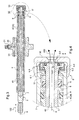
- FIG. 1 is an axial section view of a shock absorber in accordance with the invention
- FIG. 2 is an axial section view of a variant of the FIG. 1 shock absorber in which a vent arrangement is provided that is designed to enable the rod-and-piston assembly to penetrate maximally into the inside of the tubular body, and also to retain said assembly in this position;
- FIG. 3 is an axial section view showing the central portion of the FIG. 2 shock absorber in the maximally contracted position of the rod-and-piston, with suction being formed while the shock absorber is in use;
- FIG. 4 shows a detail IV of FIG. 3 in which the above-mentioned vent-forming arrangement can be seen more clearly in the open position (the position shown), which arrangement serves to form suction in the closed position (with the nut tightened);
- FIG. 5 shows the shock absorber of FIGS. 2 to 4 in various axial positions of its rod-and-piston assembly, with a) showing a middle position, b) showing a maximum penetration position of the rod-and-piston assembly achieved as a result of opening the vent, and c) showing a maximally-extended position of the rod-and-piston assembly;
- FIG. 6 is an axial section view of yet another variant of the shock absorber, in which each annular auxiliary chamber communicates with the associated compensation chamber via a channel fitted with its own constriction;
- FIG. 7 is an axial section view of a variant of the FIG. 6 shock absorber, in which the deformable flexible wall defining each compensation chamber is subjected externally to a small positive pressure, unlike the above-mentioned variant in which it is subjected to atmospheric pressure;
- FIG. 8 shows one of the non-return means of the shock absorber of FIGS. 6 and 7 ;
- FIG. 9 shows the star-shaped grids used for positioning and holding the flexible bags of the shock absorber of FIGS. 6 and 7 .
- FIG. 1 shows a shock absorber referenced 1 in accordance with the invention, the shock absorber having high dissipation power and practically no oil.
- This shock absorber is of the type comprising a rod-and-piston assembly 2 that is slidable in a tubular body 3 , said rod-and-piston assembly being adapted to be connected to an external source of disturbances referenced SPE (e.g. a wheel of a vehicle fitted with the shock absorber in its suspension, for a wheel that is in direct contact with the ground), and said tubular body is adapted to be connected to a structure that is to be protected, referenced S (e.g. the bodywork of the motor vehicle fitted therewith).
- SPE disturbances referenced
- S e.g. the bodywork of the motor vehicle fitted therewith
- the tubular body 3 has a cylindrical portion 4 within which an open-ended hollow central rod portion 5 extends axially, along a longitudinal axis X of the shock absorber.
- the ring 6 securely connecting the cylindrical portion 4 to the hollow central rod portion 5 thus forms the end wall of a chamber 10 that is a closed annular chamber containing a gaseous fluid, e.g. air or nitrogen.
- such a rigid closed end wall constitutes only one particular embodiment and, as described below, it is possible to provide an end wall that is not a unitary single piece, in order to provide a vent function for the purpose of making it possible both to enable the rod-and-piston assembly to penetrate maximally into the inside of the tubular body 3 in order to minimize the overall size of the shock absorber during storage or transport thereof, and also to form suction that is created while the shock absorber is in use.
- the rod-and-piston assembly is thus constituted by a rod proper 7 and by a piston 8 that slides, with sealing provided by means of gaskets 9 , in the annular space defined between the inner wall of the cylindrical portion 4 and the outer wall of the hollow central rod portion 5 .
- the cylindrical portion 4 and the hollow central rod portion 5 form between them an annular space in which the rod-and-piston assembly, which is likewise hollow, slides in sealed manner, defining a “working” chamber 11 A on the side of the piston 8 that faces towards the source of external disturbances SPE, and on the other side it defines the closed annular chamber 10 containing a gaseous fluid.
- the rod-and-piston assembly 2 co-operates with the tubular body 3 to define two working chambers 11 A and 11 B containing hydraulic fluid, each working chamber 11 A, 11 B being in permanent communication with an auxiliary chamber 12 A, 12 B containing a heterogeneous energy absorption-dissipation structure constituted by at least one porous capillary matrix 14 and an associated liquid 15 relative to which said matrix is lyophobic.
- the inside section of the rod-and-piston 2 in this example acts as the piston for the working chamber 11 B.
- the two auxiliary chambers 12 A and 12 B are annular chambers placed in the wall of the tubular body 3 on either side of a central portion 28 of said tubular body.
- Each of these annular auxiliary chambers 12 A, 12 B houses a flexible bag 13 A, 13 B containing the associated heterogeneous structure for which the porous capillary matrixes are represented herein by solids 14 , the associated liquid relative to which said matrices are lyophobic being given reference 15 .
- the liquid may be water or any other suitable liquid.
- each of the flexible bags 13 A, 13 B containing an associated heterogeneous structure 14 , 15 is arranged in the vicinity of the outer wall of the tubular body of the shock absorber, which is very favorable in terms of heat exchange with the outside.
- the two annular auxiliary chambers 12 A, 12 B in this example communicate with each other via a channel 20 formed in the central portion 28 of the tubular body and extending parallel to the axis X, which channel 20 is provided with a common constriction 21 that provides adjustable hydraulic resistance.
- each of the two working chambers 11 A and 11 B defined by the rod-and-piston assembly 2 in association with the tubular body also communicates, via respective non-return means 22 A and 22 B with an associated compensation chamber 17 A, 17 B that is arranged in the end of the tubular body 3 .
- the tubular body 3 is terminated at each of its two ends by a respective head 16 A, 16 B containing the associated compensation chamber 17 A, 17 B, each compensation chamber being defined by a deformable flexible wall 18 A, 18 B that is fastened and housed in the corresponding head 16 A, 16 B, said deformable flexible wall 18 A, 18 B being specifically subjected externally to atmospheric pressure.
- References 27 A, 27 B designate elements such as clips that enable the deformable flexible wall 18 A, 18 B to be fastened in the associated housing of the corresponding head 16 A, 16 B.
- each deformable flexible wall 18 A, 18 B it is possible to provide for each deformable flexible wall 18 A, 18 B to be subjected externally to a small amount of positive pressure by associated pressurizing means 30 A, 30 B incorporated in the head in question 16 A, 16 B.
- the two compensation chambers 17 A and 17 B are for providing hydraulic fluid continuity during movement of the rod-and-piston assembly 2 in the tubular body 3 .
- annular grids 26 A, 26 B each in the form of a hollow star or a ring (analogous to the grids shown in FIG. 9 ), which grids are arranged in the openings of each of the auxiliary annular chambers 12 A, 12 B, each grid serving to position and hold the flexible bag 13 A, 13 B that is housed in the annular auxiliary chamber in question. This ensures there is no risk of the flexible bag 13 A, 13 B being damaged while the shock absorber is in operation, in particular in the event of high levels of vibration.
- the flexible bags 13 A, 13 B are made of a material that cannot be penetrated by the hydraulic fluid, as already described in the context of the shock absorber having high dissipation power of above-mentioned document EP 1 250 439 B1.
- Each flexible bag thus contains the porous capillary matrices 14 that are immersed in an associated functional liquid 15 (working liquid), which may for example be water.
- working liquid which may for example be water.
- the other chambers of the shock absorber, naturally outside the above-mentioned annular chamber 10 that contains a gas, are then occupied by a hydraulic fluid such as oil (technological liquid).
- the tubular body 3 is terminated at each of its two ends by a head 16 A, 16 B, in this example forming a single piece with the remainder of the cylindrical portion 4 , which head contains the associated compensation chamber 17 A, 17 B.
- the non-return means 22 A, 22 B associated with each compensation chamber 17 A, 17 B are constituted specifically by check valves in the form of washers 23 A, 23 B having calibrated orifices 24 A, 24 B and bearing against the corresponding head 16 A, 16 B in order to mask connection channels 25 A, 25 B formed in said head and connecting each compensation chamber 17 A, 17 B to the associated working chamber 11 A, 11 B.
- the calibrated orifices 24 A, 24 B of each washer 23 A, 23 B constituting the non-return means 22 A, 22 B are therefore dimensioned so that the hydraulic resistance they procure is always greater in the closed position than the adjustable hydraulic resistance procured by the common constriction 21 .
- one of the two heads 16 A that has the rod-and-piston assembly 2 passing therethrough is provided with the sole sealing system 19 of the shock absorber for dealing relative to the outside, which constitutes a major advantage over prior embodiments of the prior art that require the shock absorber to have two sealing systems for sealing relative to the outside.
- FIG. 1 there is a flexible O-ring 29 arranged against the piston 8 on the rod 7 of the rod-and-piston assembly 2 , for the purpose of constituting a safety stop in the maximally-extended position of the rod-and-piston assembly 2 .
- arrows 101 and 102 respectively symbolize the extension and penetration directions of the rod-and-piston assembly 2 .
- the shock absorber is shown with its rod-and-piston assembly in a middle position, such that the available extension stroke, referenced C 1 , is substantially identical to the available penetration stroke, referenced C 2 .
- the residual stroke, referenced C 0 corresponds to the piston penetrating maximally, with the volume of gas contained in the annular chamber 10 being compressed maximally, without allowing the gas to escape.
- this residual stroke C 0 it can be seen that it is possible in certain circumstances to eliminate this residual stroke C 0 in order to achieve total penetration of the rod-and-piston assembly so as to maximize the compactness of the shock absorber.
- FIGS. 2 to 4 show a variant of the shock absorber as described above with reference to FIG. 1 , this variant presenting a structure in which fabrication and assembly are greatly simplified, as can be seen from the explanations given below.
- the cylindrical portion 4 of the tubular body 3 is then constituted by two tubes 4 A and 4 B, each of which is screwed at one end to a threaded fitting constituting the central portion 28 , and that is screwed at its other end to a respective threaded head 16 A, 16 B containing the associated compensation chamber 17 A, 17 B.
- the tubular body 3 is also constituted by a sheath portion referenced 4 C that is constituted by one or two tubes (one in this example) that is/are specifically screwed into a bore of the central fitting 28 .
- 1 shock absorber is replaced by two tubes 4 A, 4 B, two heads 16 A, 16 B, a central fitting 28 , and, in this example, a single sheath-forming tube 4 C.
- the central fitting 28 which is threaded at both ends, presents the channel 20 providing communication between the two tubular auxiliary chambers 12 A and 12 B, and it is fitted with the associated common constriction 21 .
- the closed annular chamber 10 containing a gaseous fluid has an end wall 6 ′ that is constituted in this example by an annular shoulder 6 . 1 forming part of the sheath portion 4 C of the cylindrical portion 4 of the tubular body 3 .
- This annular shoulder 6 . 1 has the hollow central rod portion 5 passing slidably therethrough with clearance (clearance 6 . 2 ), said hollow central rod 5 having an end flange 6 . 3 carrying a respective sealing gasket 6 . 5 or 6 . 6 on each of its circular faces.
- the free end of the sheath portion 4 C of the cylindrical portion 4 has an outside thread in order to receive a nut 30 for clamping the end flange 6 . 3 of the hollow central rod portion 5 against the shoulder 6 . 1 of the sheath portion 4 C, or for disengaging said flange 6 . 3 from said shoulder 6 . 1 .
- the end flange 6 . 3 can be clamped to bear in leaktight manner against the shoulder 6 . 1 , which corresponds to the operating position of the shock absorber, but it can also be disengaged therefrom (the position shown in FIG.
- the shock absorber is then ultra-compact. Once this position has been reached, it suffices for the operator to tighten the nut 30 once more so as to re-seal the end wall 6 ′. It can thus be understood that this maximum penetration position of the rod-and-piston is maintained (the nut 30 being tightened once more) by the suction that is created in the chamber 10 as soon as said rod-and-piston leaves this position (this suction constituting effective return means that are both simple and reliable).
- the shock absorber When the shock absorber needs to be reassembled or installed starting from this maximum penetration position of the rod, the operator can easily pull on the rod to bring it into a middle position while the nut 30 is still tight, thereby forming a small amount of suction in the chamber 10 that was initially at atmospheric pressure.
- the central orifice 31 of the nut 30 extends the central channel referenced 40 of the central rod portion 5 so as to allow the fluid to pass during movements of the rod-and-piston.
- the nut 30 When it is desired to store or transport the shock absorber, the nut 30 is loosened, and the rod-and-piston can be pushed in to the maximum in order to have a shock absorber that is ultra-compact for storage or transport.
- the pressure in the chamber 10 then remains equal to atmospheric pressure, thereby excluding any danger during handling of the shock absorber.
- FIG. 5 a) shows the state of the above-described shock absorber with the rod-and-piston in its middle position (a small amount of suction that exists in the chamber 10 ), b) shows said rod-and-piston in its maximum penetration position over the entire stroke C 2 , with the residual stroke C 0 that is maintained insofar as the shock absorber is in the operating state (the pressure in the chamber 10 is then equal to atmospheric pressure), and finally c) shows the maximally-extended position of the rod-and-piston over the entire stroke C 1 (with suction greater than in a) then existing in the chamber 10 ).
- the piston 9 of the rod-and-piston assembly 2 occupies a neutral position (the movement of the rod 7 , written ⁇ X(t) in FIG. 1 , is zero) such as the position shown in FIGS. 1 , 2 , and 5 a ), with this resulting from the equilibrium between the weight of the motor vehicle and the force of the return spring of the suspension (not shown).
- the hydraulic pressures in the working chambers 11 A and 11 B, and also in the inside volume of the central channel 40 are then the same throughout, and they are equal to atmospheric pressure because of the presence of the calibrated orifices 24 A, 24 B in the check valves 23 A, 23 B, and also in this example because of the through channel 20 having the constriction 21 .
- porous capillary matrices 14 contained in the flexible bags 13 A, 13 B and immersed in the functional liquid 15 have inside spaces that are then empty. It can easily be understood that a small positive pressure in the annular chamber containing the gas 10 has no influence on the value of the pressure that exists in the hydraulic pool of the shock absorber, nor on the behavior of the heterogeneous structures 14 , 15 contained in the two flexible bags 13 A, 13 B.
- shock absorber In dynamic operation of the shock absorber, it is appropriate to distinguish between two operating regimes, comprising a first regime that is said to be “Newtonian” that is the same as the only operating regime of conventional hydraulic or oleo-pneumatic shock absorbers, and another regime, referred to as a “surface-energy” regime, that makes use of the heterogeneous energy absorption-dissipation structures, as described in document EP 1 250 539 B1 and in the above-mentioned 2007 publication.
- the Newtonian regime corresponds to mechanical energy dissipation and it is the regime that is commonly to be found in conventional hydraulic or oleo-pneumatic shock absorbers, with the viscous liquid being throttled through calibrated orifices so as to transform friction energy into heat, with the heat being given off to the outside.
- the movement ⁇ X(t) of the rod 7 with a force F(t) gives rise to variation in the hydraulic pressures in the working chambers 11 A, 11 B, with that resulting in the liquid being driven along the channel 20 .
- the pressure inside the annular auxiliary chambers 12 A, 12 B housing the flexible bag 13 A, 13 B remains moderate, and in any event insufficient for causing the functional liquid to enter into the pore space in the matrices of the heterogeneous structure, insofar as said pressure is less than the Laplace capillary pressure that corresponds to the pressure P int for causing the functional liquid to intrude into the pore space (of volume V pores ).
- the volume of the flexible bags 13 A, 13 B remains practically constant, which means that the heterogeneous structures 14 , 15 do not contribute to dissipating energy during the Newtonian regime.
- ⁇ dot over (X) ⁇ of the rod-and-piston assembly 2 exceeds a critical value ⁇ dot over (X) ⁇ cr , e.g. a value of the order of 0.1 for private cars, then the hydraulic resistance provided by the constriction 21 increases considerably, and gives rise to a large pressure increase in one of the annular auxiliary chambers 12 A or 12 B until reaching the limit value for the Laplace capillary pressure.
- a critical value ⁇ dot over (X) ⁇ cr e.g. a value of the order of 0.1 for private cars
- the fast movement of the rod-and-piston assembly 2 causes the functional liquid to intrude into the inside spaces of the matrices of the heterogeneous structure in one of the flexible bags (the bag in which the pressure increases), such that the volume of the bag in question decreases considerably, and more precisely by the value V pores .
- the volume of technological liquid (oil) expelled from the central channel 40 under high pressure cannot be delivered via the constriction 21 into the annular auxiliary chamber 12 A because of the high resistance of the constriction.
- the expelled volume is constrained to compress the corresponding flexible bag 13 B, and the volume decrease ⁇ V of this bag is equal to a value that is equivalent to the filled pore volume V pores of the matrix or matrices contained inside the flexible bag 13 B.
- the pressure exerted in the annular auxiliary chamber 12 B then exceeds the value of the Laplace capillary pressure (intrusion pressure P int ), thereby forcing the functional liquid to intrude into the porous matrix or matrices in question.
- the volume of the space increases, and the pressure therein decreases.
- the suction in the other annular auxiliary chamber 12 A then causes the associated heterogeneous structure to expand with spontaneous expulsion of the functional liquid at the pressure P exp (where P exp ⁇ P int ) out from the pores in the porous matrices located in the flexible bag 13 A, possibly together with the check valve 23 A opening simultaneously, so as to provide additional liquid filling using liquid coming from the compensation chamber 17 A under the drive of atmospheric pressure.
- the piston 8 then expels the liquid from the working chamber 11 A and the associated annular auxiliary chamber 12 A, thereby producing compression in the flexible bag 13 A and forced intrusion of the functional liquid into the pore space of the matrix of the associated heterogeneous structure 14 , 15 .
- suction is produced in the other annular auxiliary chamber 12 B, thereby initiating spontaneous expulsion of the functional liquid 15 from the pores of the porous matrix 14 of the heterogeneous structure housed in the flexible bag 13 B.
- the opening of the check valve 23 B once more guarantees fluid continuity in the annular auxiliary chamber 12 B, possibly because of the arrival of additional technological liquid from the associated compensation chamber 17 B.
- sheath portion 4 C with its end wall 6 ′ fitted with a nut 30 associated with a vent-forming system.
- the sheath portion 4 C is either inserted as a force-fit in the central portion 28 of the body portion that is made as a single piece 4 ( FIG. 6 variant), or else, as described above, that is screwed into a bore of the central portion 28 of the body portion that is made as a single piece 4 (variant of FIG. 7 ), with a central gasket 28 ′ providing sealing.
- each of these chambers communicates with the associated compensation chamber 17 A, 17 B via a respective channel 20 A, 20 B formed in the corresponding head 16 A, 16 B of the tubular body, each channel 20 A, 20 B also being fitted with its own constriction 21 A, 21 B.
- the non-return means 22 A, 22 B are then slightly modified, as shown in FIG. 8 , in which there can be seen a check valve 23 A in profile view (at a)) and in face view (at b)).
- the hydraulic resistance provided by the non-return means 22 A, 22 B in the closed position needs once more to be greater than the adjustable hydraulic resistance provided by each of the constrictions 21 A, 21 B.
- FIG. 9 shows in isolation the positioning and holding grids for the flexible bags 13 A, 13 B that contain the heterogeneous structures of the shock absorber.
- a shock absorber having the internal vent arrangement so as to be capable of being ultra-compact there can be seen in a), the grid 26 A that is normally engaged on the free end of the hollow central rod portion 5 , and in b), the grid 26 B that is normally engaged on the nut 30 , both of these grids 26 A and 26 B being in the form of a star with a circular hollow in its central portion.
- the flexible wall 18 B of the compensation chamber 17 B (which is beside the structure to be protected) to be subjected externally, not to atmospheric pressure as described above, but instead to a small amount of positive pressure (e.g. 0.5 bar to 1.0 bar) as generated by a mechanical or pneumatic spring, and to do the same for the other flexible wall 18 A using a slightly greater pressure (e.g. in the range 0.5 bar to 1 bar), thereby better guaranteeing fluid continuity and speed of response.
- a slightly greater pressure e.g. in the range 0.5 bar to 1 bar
- FIG. 7 shows pressurizing means 30 A, 30 B that are incorporated in the corresponding head 16 A, 16 B and that provide the desired small positive pressure.
- a pressurizing chamber 31 A, 31 B that is closed by a cover 32 A, 32 B and that holds a plate 33 A, 33 B fitted with a coupling piece 34 A, 34 B for use in filling the corresponding pressurizing chamber with an appropriate fluid.
- FIGS. 6 and 7 are particularly advantageous for a shock absorber that operates in a position that is essentially vertical, since they avoid liquid being delivered from one compensation chamber to the other under the effect of gravity (where such delivery can occur in the variants of FIGS. 1 to 5 ).
- having two separate constrictions 21 A and 21 B enables fine adjustment to be performed so as to guarantee that the asymmetry of the characteristic of the shock absorber is constant, with this adjustment being made once and for all on initial assembly of the shock absorber. To perform this adjustment, it is always ensured that the return force of the shock absorber is set to a value that is higher than the impact force.
- the invention may be applied to fields other than motor vehicle suspensions, for example to anti-seismic systems, to supports for gas, oil, or steam pipes, or to supports for public building works, and also to anti-vibration skids, with the above-mentioned advantages of greater effectiveness associated with high dissipation power and great compactness of the dissipation devices and systems.
- the rod-and-piston assembly 2 may be adapted to be connected to the source of external disturbances SPE or to the structure that is to be protected S, and the tubular body may be adapted to be connected to the structure that is to be protected S or to the source of external disturbances SPE.
Landscapes
- Engineering & Computer Science (AREA)
- General Engineering & Computer Science (AREA)
- Mechanical Engineering (AREA)
- Fluid-Damping Devices (AREA)
Abstract
Description
-
- the two auxiliary chambers are annular chambers formed in the wall of the tubular body on either side of central portion of said tubular body, each of said annular auxiliary chambers housing a flexible bag containing the associated heterogeneous structure; and
- each of the two working chambers also communicates via respective non-return means with an associated compensation chamber that is arranged in the corresponding end of the tubular body, said compensation chambers ensuring hydraulic fluid continuity during movements of the rod-and-piston assembly in the tubular body.
E=(P int −P exp)·V pores.
E=(P int −P exp)·V pores.
Claims (17)
Applications Claiming Priority (3)
| Application Number | Priority Date | Filing Date | Title |
|---|---|---|---|
| FR1057096 | 2010-09-07 | ||
| FR1057096A FR2964434B1 (en) | 2010-09-07 | 2010-09-07 | SHOCK ABSORBER WITH DISSIPATIVE AND PRACTICALLY NO OIL |
| PCT/EP2011/065488 WO2012032088A1 (en) | 2010-09-07 | 2011-09-07 | Virtually oil-free shock absorber having high dissipative capacity |
Publications (2)
| Publication Number | Publication Date |
|---|---|
| US20130189138A1 US20130189138A1 (en) | 2013-07-25 |
| US8925697B2 true US8925697B2 (en) | 2015-01-06 |
Family
ID=43927618
Family Applications (1)
| Application Number | Title | Priority Date | Filing Date |
|---|---|---|---|
| US13/820,977 Expired - Fee Related US8925697B2 (en) | 2010-09-07 | 2011-09-07 | Virtually oil-free shock absorber having high dissipative capacity |
Country Status (8)
| Country | Link |
|---|---|
| US (1) | US8925697B2 (en) |
| EP (1) | EP2614269A1 (en) |
| JP (1) | JP5667298B2 (en) |
| KR (1) | KR101506020B1 (en) |
| CN (1) | CN103119320B (en) |
| FR (1) | FR2964434B1 (en) |
| RU (1) | RU2547023C2 (en) |
| WO (1) | WO2012032088A1 (en) |
Cited By (1)
| Publication number | Priority date | Publication date | Assignee | Title |
|---|---|---|---|---|
| US11204075B2 (en) | 2018-04-10 | 2021-12-21 | Textron Innovations, Inc. | Free-floating washer for rebound damping |
Families Citing this family (5)
| Publication number | Priority date | Publication date | Assignee | Title |
|---|---|---|---|---|
| NO341043B1 (en) * | 2016-04-22 | 2017-08-14 | Tech Damper As | Subsea damper rod |
| CN108591339B (en) * | 2018-05-24 | 2023-07-07 | 太原科技大学 | A liquid drop spring vibration isolation device and vibration isolation method thereof |
| FR3102524B1 (en) * | 2019-10-29 | 2021-11-12 | Safran Landing Systems | Diaphragm holder for oleopneumatic type shock absorber |
| CN111271255B (en) * | 2020-03-03 | 2021-10-29 | 湖南诚跃新能源有限公司 | Air compressor for compressing gas and improving gas pressure |
| CN112610481B (en) * | 2020-12-22 | 2022-09-06 | 克诺尔南口供风设备(北京)有限公司 | Stress balance's single screw air compressor machine for locomotive |
Citations (4)
| Publication number | Priority date | Publication date | Assignee | Title |
|---|---|---|---|---|
| GB1188453A (en) | 1967-02-14 | 1970-04-15 | Hoesch Ag | Level-Regulating Hydro-Pneumatic Suspension Unit, Particularly for Motor Vehicles |
| EP1250539A1 (en) | 2000-01-26 | 2002-10-23 | Sarl D L D International | Damper with high dissipating power |
| US8052128B2 (en) * | 2007-09-08 | 2011-11-08 | Zf Friedrichshafen Ag | Self-pumping hydropneumatic spring strut |
| US20120186923A1 (en) * | 2010-09-29 | 2012-07-26 | Toyota Jidosha Kabushiki Kaisha | Colloidal damper |
Family Cites Families (4)
| Publication number | Priority date | Publication date | Assignee | Title |
|---|---|---|---|---|
| UA18905A (en) * | 1993-06-09 | 1997-12-25 | Костянтин Іванович Луданов | Hydraulic impact suppressor |
| FR2728037B1 (en) | 1994-12-09 | 1997-05-30 | Dld International | HETEROGENEOUS ENERGY STORAGE OR DISSIPATION STRUCTURE, METHODS OF USING SUCH A STRUCTURE, AND ASSOCIATED APPARATUS FOR STORAGE OR ENERGY DISSIPATION |
| KR100360594B1 (en) | 2000-01-19 | 2002-11-13 | 한미약품공업 주식회사 | Expression and secretion vector for human interferon alpha and process for producing human interferon alpha by employing same |
| RU2309307C1 (en) * | 2006-07-24 | 2007-10-27 | Московский инженерно-физический институт (государственный университет) | Method for absorbing of impact energy using heterogeneous system |
-
2010
- 2010-09-07 FR FR1057096A patent/FR2964434B1/en active Active
-
2011
- 2011-09-07 WO PCT/EP2011/065488 patent/WO2012032088A1/en not_active Ceased
- 2011-09-07 KR KR1020137008805A patent/KR101506020B1/en not_active Expired - Fee Related
- 2011-09-07 JP JP2013527589A patent/JP5667298B2/en not_active Expired - Fee Related
- 2011-09-07 EP EP11754405.6A patent/EP2614269A1/en not_active Withdrawn
- 2011-09-07 CN CN201180042906.4A patent/CN103119320B/en not_active Expired - Fee Related
- 2011-09-07 RU RU2013115380/11A patent/RU2547023C2/en not_active IP Right Cessation
- 2011-09-07 US US13/820,977 patent/US8925697B2/en not_active Expired - Fee Related
Patent Citations (5)
| Publication number | Priority date | Publication date | Assignee | Title |
|---|---|---|---|---|
| GB1188453A (en) | 1967-02-14 | 1970-04-15 | Hoesch Ag | Level-Regulating Hydro-Pneumatic Suspension Unit, Particularly for Motor Vehicles |
| EP1250539A1 (en) | 2000-01-26 | 2002-10-23 | Sarl D L D International | Damper with high dissipating power |
| US6615959B2 (en) * | 2000-01-26 | 2003-09-09 | Sarl Dld International | Damper with high dissipating power |
| US8052128B2 (en) * | 2007-09-08 | 2011-11-08 | Zf Friedrichshafen Ag | Self-pumping hydropneumatic spring strut |
| US20120186923A1 (en) * | 2010-09-29 | 2012-07-26 | Toyota Jidosha Kabushiki Kaisha | Colloidal damper |
Cited By (1)
| Publication number | Priority date | Publication date | Assignee | Title |
|---|---|---|---|---|
| US11204075B2 (en) | 2018-04-10 | 2021-12-21 | Textron Innovations, Inc. | Free-floating washer for rebound damping |
Also Published As
| Publication number | Publication date |
|---|---|
| JP2013536930A (en) | 2013-09-26 |
| RU2013115380A (en) | 2014-10-20 |
| KR101506020B1 (en) | 2015-03-25 |
| FR2964434B1 (en) | 2012-08-24 |
| FR2964434A1 (en) | 2012-03-09 |
| RU2547023C2 (en) | 2015-04-10 |
| US20130189138A1 (en) | 2013-07-25 |
| CN103119320B (en) | 2015-08-26 |
| EP2614269A1 (en) | 2013-07-17 |
| KR20130052672A (en) | 2013-05-22 |
| WO2012032088A1 (en) | 2012-03-15 |
| JP5667298B2 (en) | 2015-02-12 |
| CN103119320A (en) | 2013-05-22 |
Similar Documents
| Publication | Publication Date | Title |
|---|---|---|
| US12441151B1 (en) | Gas spring assembly for a vehicle suspension system | |
| US12246572B1 (en) | Load dependent damper for a vehicle suspension system | |
| US8925697B2 (en) | Virtually oil-free shock absorber having high dissipative capacity | |
| US6311962B1 (en) | Shock absorber with external air cylinder spring | |
| US5775677A (en) | Air or gas sprung and dampened shock absorber | |
| US6135434A (en) | Shock absorber with positive and negative gas spring chambers | |
| EP2064461B1 (en) | Shock absorber with two pressurized chambers and a method for adjusting pressure balance between said shock absorber's two chambers | |
| US5538276A (en) | Tunable air spring | |
| CN108999911B (en) | Strut assembly with combined gas spring and damper | |
| CN110998129B (en) | Pressurized telescopic front fork leg, front fork and vehicle | |
| CN112243413B (en) | Shock absorber unit for vehicle chassis with level adjustment | |
| US20100116608A1 (en) | Suspension and damping device for motor vehicles | |
| WO1994018488A1 (en) | Pulsation damper device | |
| WO2024189626A1 (en) | Impact attenuation device | |
| AU2017206165A1 (en) | Shell Reservoir Damper | |
| US6491289B1 (en) | Oleo-pneumatic shock absorbing system | |
| WO1996033905A1 (en) | An air or gas sprung and dampened shock absorber |
Legal Events
| Date | Code | Title | Description |
|---|---|---|---|
| AS | Assignment |
Owner name: WALDEN ASSOCIATES LTD., S.A., PANAMA Free format text: ASSIGNMENT OF ASSIGNORS INTEREST;ASSIGNOR:EROSHENKO, VALENTIN;REEL/FRAME:030180/0653 Effective date: 20130320 |
|
| AS | Assignment |
Owner name: WALDEN ASSOCIATES LTD., S.A., PANAMA Free format text: CORRECTIVE ASSIGNMENT TO CORRECT THE ASSIGNEE ADDRESS FROM: RECARDO J. ALFARO AVENUE TO RICARDO J. ALFARO AVENUE PREVIOUSLY RECORDED ON REEL 030180 FRAME 0653. ASSIGNOR(S) HEREBY CONFIRMS THE ASSIGNEE: WALDEN ASSOCIATES LTD., S.A. RICARDO J. ALFARO AVENUE THE CENTURY TOWER-OFFICE NO. 713 PANAMA CITY, PANAMA;ASSIGNOR:EROSHENKO, VALENTIN;REEL/FRAME:030294/0946 Effective date: 20130320 |
|
| FEPP | Fee payment procedure |
Free format text: PAYOR NUMBER ASSIGNED (ORIGINAL EVENT CODE: ASPN); ENTITY STATUS OF PATENT OWNER: LARGE ENTITY |
|
| FEPP | Fee payment procedure |
Free format text: MAINTENANCE FEE REMINDER MAILED (ORIGINAL EVENT CODE: REM.); ENTITY STATUS OF PATENT OWNER: LARGE ENTITY |
|
| LAPS | Lapse for failure to pay maintenance fees |
Free format text: PATENT EXPIRED FOR FAILURE TO PAY MAINTENANCE FEES (ORIGINAL EVENT CODE: EXP.); ENTITY STATUS OF PATENT OWNER: LARGE ENTITY |
|
| STCH | Information on status: patent discontinuation |
Free format text: PATENT EXPIRED DUE TO NONPAYMENT OF MAINTENANCE FEES UNDER 37 CFR 1.362 |
|
| FP | Lapsed due to failure to pay maintenance fee |
Effective date: 20190106 |