US8925581B2 - Hydraulic suction line - Google Patents
Hydraulic suction line Download PDFInfo
- Publication number
- US8925581B2 US8925581B2 US13/561,646 US201213561646A US8925581B2 US 8925581 B2 US8925581 B2 US 8925581B2 US 201213561646 A US201213561646 A US 201213561646A US 8925581 B2 US8925581 B2 US 8925581B2
- Authority
- US
- United States
- Prior art keywords
- bore
- sump
- suction line
- tube
- housing
- Prior art date
- Legal status (The legal status is an assumption and is not a legal conclusion. Google has not performed a legal analysis and makes no representation as to the accuracy of the status listed.)
- Active, expires
Links
Images


Classifications
-
- F—MECHANICAL ENGINEERING; LIGHTING; HEATING; WEAPONS; BLASTING
- F16—ENGINEERING ELEMENTS AND UNITS; GENERAL MEASURES FOR PRODUCING AND MAINTAINING EFFECTIVE FUNCTIONING OF MACHINES OR INSTALLATIONS; THERMAL INSULATION IN GENERAL
- F16L—PIPES; JOINTS OR FITTINGS FOR PIPES; SUPPORTS FOR PIPES, CABLES OR PROTECTIVE TUBING; MEANS FOR THERMAL INSULATION IN GENERAL
- F16L41/00—Branching pipes; Joining pipes to walls
- F16L41/08—Joining pipes to walls or pipes, the joined pipe axis being perpendicular to the plane of the wall or to the axis of another pipe
- F16L41/086—Joining pipes to walls or pipes, the joined pipe axis being perpendicular to the plane of the wall or to the axis of another pipe fixed with screws
-
- F—MECHANICAL ENGINEERING; LIGHTING; HEATING; WEAPONS; BLASTING
- F04—POSITIVE - DISPLACEMENT MACHINES FOR LIQUIDS; PUMPS FOR LIQUIDS OR ELASTIC FLUIDS
- F04B—POSITIVE-DISPLACEMENT MACHINES FOR LIQUIDS; PUMPS
- F04B23/00—Pumping installations or systems
- F04B23/02—Pumping installations or systems having reservoirs
-
- F—MECHANICAL ENGINEERING; LIGHTING; HEATING; WEAPONS; BLASTING
- F16—ENGINEERING ELEMENTS AND UNITS; GENERAL MEASURES FOR PRODUCING AND MAINTAINING EFFECTIVE FUNCTIONING OF MACHINES OR INSTALLATIONS; THERMAL INSULATION IN GENERAL
- F16H—GEARING
- F16H57/00—General details of gearing
- F16H57/04—Features relating to lubrication or cooling or heating
- F16H57/045—Lubricant storage reservoirs, e.g. reservoirs in addition to a gear sump for collecting lubricant in the upper part of a gear case
- F16H57/0452—Oil pans
-
- Y—GENERAL TAGGING OF NEW TECHNOLOGICAL DEVELOPMENTS; GENERAL TAGGING OF CROSS-SECTIONAL TECHNOLOGIES SPANNING OVER SEVERAL SECTIONS OF THE IPC; TECHNICAL SUBJECTS COVERED BY FORMER USPC CROSS-REFERENCE ART COLLECTIONS [XRACs] AND DIGESTS
- Y10—TECHNICAL SUBJECTS COVERED BY FORMER USPC
- Y10T—TECHNICAL SUBJECTS COVERED BY FORMER US CLASSIFICATION
- Y10T137/00—Fluid handling
- Y10T137/8593—Systems
- Y10T137/86348—Tank with internally extending flow guide, pipe or conduit
- Y10T137/86372—Inlet internally extending
-
- Y—GENERAL TAGGING OF NEW TECHNOLOGICAL DEVELOPMENTS; GENERAL TAGGING OF CROSS-SECTIONAL TECHNOLOGIES SPANNING OVER SEVERAL SECTIONS OF THE IPC; TECHNICAL SUBJECTS COVERED BY FORMER USPC CROSS-REFERENCE ART COLLECTIONS [XRACs] AND DIGESTS
- Y10—TECHNICAL SUBJECTS COVERED BY FORMER USPC
- Y10T—TECHNICAL SUBJECTS COVERED BY FORMER US CLASSIFICATION
- Y10T29/00—Metal working
- Y10T29/49—Method of mechanical manufacture
- Y10T29/49826—Assembling or joining
- Y10T29/49947—Assembling or joining by applying separate fastener
Definitions
- This invention relates generally to power hydraulic systems and more specifically to a suction hydraulic line that connects a fluid sump with an inlet of a hydraulic pump mounted externally of a fluid sump especially for an automatic transmission.
- a suction line for a hydraulic pump is required if the hydraulic pump is located externally from a housing containing a sump whose fluid level is lower than the pump's inlet.
- a suction inlet line is typically located close to the bottom of a sump to avoid suction of air when the fluid level is low.
- a suction line may be attached to the sump's internal wall by means of internally located seals and fasteners.
- the sump wall may include an opening to the external side, which is also sealed externally to provide an interface with the manifold of the pump assembly.
- a suction line in this arrangement is required when an L-shaped suction line conducts fluid from the bottom of the sump to the side wall.
- the suction line must prevent movement in the vertical direction by means of additional fasteners.
- a pump suction line assembly includes a sump including a wall formed with a bore and a seat, a tube including an inlet, an outlet, a length connecting the outlet and inlet, and a flange contacting the seat, a housing, a seal fitted in the bore and contacting the flange and the housing, and fasteners that compress the seal, secure the tube to the wall, and secure the sump to the housing.
- a method for installing the suction line includes inserting the suction line into a bore formed in a sump, fitting a flared length of the suction line into the bore, seating a flange of the suction line against the sump at the bore, inserting a seal between the flange and a housing, and using fasteners to compress the seal, secure the suction line to the sump, and secure the sump to the housing.
- the pump suction line assembly provides means for installing into a sump an L-shaped suction tube with a single seal and minimum size opening in the wall of the sump.
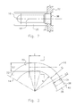
- FIG. 1 is a side view of a suction line assembly installed in a sump
- FIG. 2 is a top view showing outlet of the suction line fitted on the pump manifold flange
- FIG. 3 is a side view of a suction line assembly with a minimum radius of curvature.
- FIGS. 1 and 2 show a sump 10 containing hydraulic fluid whose upper surface 12 is higher than the inlet 14 of a suction line 16 .
- Suction line 16 is preferably a hollow thin walled tube having a circular cross section. The suction line 16 is restricted from rotation about axis 18 by a slot 20 formed in the sump wall 22 .
- the suction line 16 is formed with a 90 degree arcuate length section 30 , preferable having a constant radius; a straight section 32 , which extends between suction line 16 inlet 14 and the arcuate length section 30 ; and a second straight section 34 , which extends between the outlet 36 and the arcuate length section 30 .
- Straight section 34 is formed with a flare 38 , which has a larger diameter than the diameter of the arcuate length section 30 .
- the outlet 36 of suction line 16 is encircled by a radial seating flange 40 .
- the wall 22 of the sump 10 is formed with a bore 37 aligned with axis 18 , and a counter bore 39 aligned with the bore.
- the suction line 16 is inserted through the bore 37 and counter bore 39 such that radial seating flange 40 is brought into contact with a shoulder 44 on a boss 46 formed in the sump wall 22 where the bore 37 and counter bore 39 meet.
- a compression seal 48 is located between radial seating flange 40 and a housing 50 , located outside the sump 10 , such as a pump manifold.
- Mechanical fasteners 52 engage screw threads in the boss 46 . The fasteners 52 compress seal 48 between radial seating flange 40 and the housing 50 , secure the suction line 16 to the sump wall 22 , and secure the sump 10 to the housing 50 .
- the outer diameter of straight section or flair 34 is substantially equal to the diameter of the bore 37 , thereby allow vertical alignment of the suction line 16 .
- the radial seating flange 40 is preferably marked with a symbol (not shown) indicating the direction of the bend in the arcuate length section 30 of the tube 16 or the plane of the arcuate length section.
- the outer diameter of the compression seal 48 is equal to or slightly smaller than the inner diameter of counter bore 39 , thereby providing a reliable preloaded hydraulic seal among the bore 37 , radial seating flange 40 and housing 50 , when the fasteners 52 are tightened.
- the internal radius R of the arcuate length section 30 of the suction line 16 is a function of the outer diameter D of suction tube 16 , the inner diameter D 3 of the bore 37 in boss 46 , and the depth E of the bore 37 , i.e., the axial length of bore 37 , as defined by the formula
- the depth E of the bore 37 should be reduced and the difference between the outer diameter of the flare 34 and the outer diameter of the suction line 16 should be increased.
- the method of installing the suction line and securing it to the shoulder 44 includes inserting the suction line into the bore formed in shoulder 44 of the boss 46 , fitting the outer diameter of the flare 38 into the bore, radial seating flange 40 against the flat surface of the counter bore in shoulder 44 , inserting compression seal 48 between radial seating flange 40 and housing 50 , and securing fasteners 52 between housing 50 and the boss 46 .
- the equation can be used to calculate the minimum bend radius R of the suction line 16 that can be freely inserted into housing bore depending on the outer diameter D 3 of flare 38 , the outer diameter D of the suction line outer diameter, and the depth E of the shoulder 44 in sump wall boss 46 .
Abstract
Description
Claims (10)
R=(E 2/4+(D3−D)2)/(2(D3−D))
R=(E 2/4+(D3−D)2)/(2(D3−D))
Priority Applications (3)
| Application Number | Priority Date | Filing Date | Title |
|---|---|---|---|
| US13/561,646 US8925581B2 (en) | 2012-07-30 | 2012-07-30 | Hydraulic suction line |
| CN201310319352.9A CN103574195B (en) | 2012-07-30 | 2013-07-26 | Hydraulic suction line |
| DE102013107998.9A DE102013107998B4 (en) | 2012-07-30 | 2013-07-26 | Hydraulic suction line |
Applications Claiming Priority (1)
| Application Number | Priority Date | Filing Date | Title |
|---|---|---|---|
| US13/561,646 US8925581B2 (en) | 2012-07-30 | 2012-07-30 | Hydraulic suction line |
Publications (2)
| Publication Number | Publication Date |
|---|---|
| US20140028022A1 US20140028022A1 (en) | 2014-01-30 |
| US8925581B2 true US8925581B2 (en) | 2015-01-06 |
Family
ID=49912358
Family Applications (1)
| Application Number | Title | Priority Date | Filing Date |
|---|---|---|---|
| US13/561,646 Active 2033-06-13 US8925581B2 (en) | 2012-07-30 | 2012-07-30 | Hydraulic suction line |
Country Status (3)
| Country | Link |
|---|---|
| US (1) | US8925581B2 (en) |
| CN (1) | CN103574195B (en) |
| DE (1) | DE102013107998B4 (en) |
Cited By (1)
| Publication number | Priority date | Publication date | Assignee | Title |
|---|---|---|---|---|
| US20180135478A1 (en) * | 2016-11-17 | 2018-05-17 | K.J. Manufacturing Co. | Complete volume draining oil pan and device |
Families Citing this family (1)
| Publication number | Priority date | Publication date | Assignee | Title |
|---|---|---|---|---|
| KR101757773B1 (en) * | 2016-10-18 | 2017-07-14 | 하진상 | Joint flange using extended thickness and cutting pipe manufacturing method the same |
Citations (10)
| Publication number | Priority date | Publication date | Assignee | Title |
|---|---|---|---|---|
| US4364517A (en) | 1980-07-11 | 1982-12-21 | Etheridge Robert E | Hopper cleaner attachment |
| US4765507A (en) * | 1986-01-24 | 1988-08-23 | Ecodyne Corporation | Pressure vessel with an improved sidewall structure |
| US5988134A (en) | 1996-02-20 | 1999-11-23 | Navistar International Transportation Corp | Two piece locking oil pickup tube assembly |
| US6041752A (en) | 1998-11-04 | 2000-03-28 | Technology Holdings, Inc. | Moldable integrated oil pan and suction tube for an internal combustion engine |
| US6241485B1 (en) * | 1999-12-29 | 2001-06-05 | John W. Warwick | Wastewater flow control system |
| US6742490B2 (en) | 2002-09-30 | 2004-06-01 | International Engine Intellectual Property Company, Llc | Oil pickup tube assembly |
| US20060022458A1 (en) * | 2004-07-27 | 2006-02-02 | Timothy Droste | Sealed fluid connector assembly |
| US7237807B2 (en) * | 2003-05-21 | 2007-07-03 | Calsonic Kansei Corporation | Pipe connecting structure for a heat exchanger |
| US7296590B2 (en) | 2004-02-25 | 2007-11-20 | Sysmex Corporation | Liquid suction device |
| US7475563B2 (en) * | 2005-08-25 | 2009-01-13 | Mccarrell Billy Ray | Multifunction cooler |
Family Cites Families (5)
| Publication number | Priority date | Publication date | Assignee | Title |
|---|---|---|---|---|
| US868548A (en) * | 1906-07-02 | 1907-10-15 | William J Griffin | Compressed-air tank. |
| PT1479985T (en) | 2002-01-17 | 2017-08-03 | Alfa Laval Corp Ab | Submerged evaporator comprising a plate heat exchanger and a cylindric casing where the plate heat exchanger is arranged |
| US6676167B2 (en) * | 2002-05-20 | 2004-01-13 | Visteon Global Technologies, Inc. | Air conditioning block fitting with two surface sealing |
| JP2006300292A (en) * | 2005-04-25 | 2006-11-02 | Calsonic Kansei Corp | Pipe connecting structure |
| CN202274227U (en) * | 2011-06-22 | 2012-06-13 | 江苏迈能高科技有限公司 | D-shaped water outgoing pipe of horizontal pressure-bearing heat-storage water tank |
-
2012
- 2012-07-30 US US13/561,646 patent/US8925581B2/en active Active
-
2013
- 2013-07-26 CN CN201310319352.9A patent/CN103574195B/en active Active
- 2013-07-26 DE DE102013107998.9A patent/DE102013107998B4/en active Active
Patent Citations (10)
| Publication number | Priority date | Publication date | Assignee | Title |
|---|---|---|---|---|
| US4364517A (en) | 1980-07-11 | 1982-12-21 | Etheridge Robert E | Hopper cleaner attachment |
| US4765507A (en) * | 1986-01-24 | 1988-08-23 | Ecodyne Corporation | Pressure vessel with an improved sidewall structure |
| US5988134A (en) | 1996-02-20 | 1999-11-23 | Navistar International Transportation Corp | Two piece locking oil pickup tube assembly |
| US6041752A (en) | 1998-11-04 | 2000-03-28 | Technology Holdings, Inc. | Moldable integrated oil pan and suction tube for an internal combustion engine |
| US6241485B1 (en) * | 1999-12-29 | 2001-06-05 | John W. Warwick | Wastewater flow control system |
| US6742490B2 (en) | 2002-09-30 | 2004-06-01 | International Engine Intellectual Property Company, Llc | Oil pickup tube assembly |
| US7237807B2 (en) * | 2003-05-21 | 2007-07-03 | Calsonic Kansei Corporation | Pipe connecting structure for a heat exchanger |
| US7296590B2 (en) | 2004-02-25 | 2007-11-20 | Sysmex Corporation | Liquid suction device |
| US20060022458A1 (en) * | 2004-07-27 | 2006-02-02 | Timothy Droste | Sealed fluid connector assembly |
| US7475563B2 (en) * | 2005-08-25 | 2009-01-13 | Mccarrell Billy Ray | Multifunction cooler |
Cited By (3)
| Publication number | Priority date | Publication date | Assignee | Title |
|---|---|---|---|---|
| US20180135478A1 (en) * | 2016-11-17 | 2018-05-17 | K.J. Manufacturing Co. | Complete volume draining oil pan and device |
| US10508571B2 (en) * | 2016-11-17 | 2019-12-17 | K.J. Manufacturing Co. | Complete volume draining oil pan and device |
| US11092048B2 (en) * | 2016-11-17 | 2021-08-17 | K.J. Manufacturing Co. | Complete volume draining oil pan and device |
Also Published As
| Publication number | Publication date |
|---|---|
| DE102013107998B4 (en) | 2023-06-07 |
| CN103574195A (en) | 2014-02-12 |
| US20140028022A1 (en) | 2014-01-30 |
| DE102013107998A1 (en) | 2014-01-30 |
| CN103574195B (en) | 2019-04-19 |
Similar Documents
| Publication | Publication Date | Title |
|---|---|---|
| RU2013120282A (en) | FILTER SYSTEM WITH A WATER SEPARATOR FOR FUEL | |
| US20110005333A1 (en) | Face seal gasket | |
| KR102026276B1 (en) | Flow volume measurement device for turbo compressor, and turbo compressor | |
| US8925581B2 (en) | Hydraulic suction line | |
| EP2829428A1 (en) | Valve device for fuel tank | |
| US20060085907A1 (en) | Flexible bathtub waste pipe assembly for bathtubs and the like | |
| US20140353087A1 (en) | Shield for transmission fluid sump | |
| EP2949934B1 (en) | Compressor sound-insulating structure and air conditioner provided with compressor having the same | |
| US9353762B2 (en) | Pressure compensating wet seal chamber | |
| US11473953B2 (en) | Sensor device with sensor connector for accommodating a clip | |
| US10591051B2 (en) | Sensor mounting structure | |
| EP3234360B1 (en) | Fluid flow adapter for a cylinder of a reciprocating compressor | |
| CN105387000B (en) | Pump casing | |
| CN107850079A (en) | Pump | |
| JP2009063546A (en) | Gas meter mounting unit | |
| CN205859488U (en) | A kind of pressure early warning sealing cap and air-conditioner | |
| CN209892898U (en) | Pipe joint installation assembly and quality detection device | |
| CN209875463U (en) | Integrated oil-injection scroll compressor | |
| CN216246608U (en) | Pressure measuring structure of flowmeter | |
| JP5712019B2 (en) | Impeller and motor connection structure | |
| CN212689996U (en) | Blasting type oil drain device | |
| JP2005016519A (en) | Fuel supply device | |
| JP2832186B2 (en) | Power divider oil leakage prevention structure | |
| CN215597732U (en) | Air conditioner and drain pipe assembly thereof | |
| US20230134178A1 (en) | Conduit Fittings for Conduit and Cable Installations |
Legal Events
| Date | Code | Title | Description |
|---|---|---|---|
| AS | Assignment |
Owner name: FORD GLOBAL TECHNOLOGIES, LLC, MICHIGAN Free format text: ASSIGNMENT OF ASSIGNORS INTEREST;ASSIGNORS:PEKARSKY, LEV;YASNOGORODSKIY, VLADIMIR;LINT, BRANDON D.;AND OTHERS;REEL/FRAME:028675/0890 Effective date: 20120726 |
|
| STCF | Information on status: patent grant |
Free format text: PATENTED CASE |
|
| MAFP | Maintenance fee payment |
Free format text: PAYMENT OF MAINTENANCE FEE, 4TH YEAR, LARGE ENTITY (ORIGINAL EVENT CODE: M1551) Year of fee payment: 4 |
|
| MAFP | Maintenance fee payment |
Free format text: PAYMENT OF MAINTENANCE FEE, 8TH YEAR, LARGE ENTITY (ORIGINAL EVENT CODE: M1552); ENTITY STATUS OF PATENT OWNER: LARGE ENTITY Year of fee payment: 8 |