US8919044B2 - Sill and opening-leaf assembly for a door that essentially is fluid-tight to a liquid or gaseous fluid and is intended to seal an opening separating two spaces in a building or monument - Google Patents
Sill and opening-leaf assembly for a door that essentially is fluid-tight to a liquid or gaseous fluid and is intended to seal an opening separating two spaces in a building or monument Download PDFInfo
- Publication number
- US8919044B2 US8919044B2 US13/825,151 US201013825151A US8919044B2 US 8919044 B2 US8919044 B2 US 8919044B2 US 201013825151 A US201013825151 A US 201013825151A US 8919044 B2 US8919044 B2 US 8919044B2
- Authority
- US
- United States
- Prior art keywords
- groove
- gasket element
- longitudinal
- dust
- assembly according
- Prior art date
- Legal status (The legal status is an assumption and is not a legal conclusion. Google has not performed a legal analysis and makes no representation as to the accuracy of the status listed.)
- Expired - Fee Related, expires
Links
Images


Classifications
-
- E—FIXED CONSTRUCTIONS
- E06—DOORS, WINDOWS, SHUTTERS, OR ROLLER BLINDS IN GENERAL; LADDERS
- E06B—FIXED OR MOVABLE CLOSURES FOR OPENINGS IN BUILDINGS, VEHICLES, FENCES OR LIKE ENCLOSURES IN GENERAL, e.g. DOORS, WINDOWS, BLINDS, GATES
- E06B7/00—Special arrangements or measures in connection with doors or windows
- E06B7/16—Sealing arrangements on wings or parts co-operating with the wings
- E06B7/18—Sealing arrangements on wings or parts co-operating with the wings by means of movable edgings, e.g. draught sealings additionally used for bolting, e.g. by spring force or with operating lever
-
- E—FIXED CONSTRUCTIONS
- E06—DOORS, WINDOWS, SHUTTERS, OR ROLLER BLINDS IN GENERAL; LADDERS
- E06B—FIXED OR MOVABLE CLOSURES FOR OPENINGS IN BUILDINGS, VEHICLES, FENCES OR LIKE ENCLOSURES IN GENERAL, e.g. DOORS, WINDOWS, BLINDS, GATES
- E06B1/00—Border constructions of openings in walls, floors, or ceilings; Frames to be rigidly mounted in such openings
- E06B1/70—Sills; Thresholds
-
- E—FIXED CONSTRUCTIONS
- E06—DOORS, WINDOWS, SHUTTERS, OR ROLLER BLINDS IN GENERAL; LADDERS
- E06B—FIXED OR MOVABLE CLOSURES FOR OPENINGS IN BUILDINGS, VEHICLES, FENCES OR LIKE ENCLOSURES IN GENERAL, e.g. DOORS, WINDOWS, BLINDS, GATES
- E06B5/00—Doors, windows, or like closures for special purposes; Border constructions therefor
- E06B5/10—Doors, windows, or like closures for special purposes; Border constructions therefor for protection against air-raid or other war-like action; for other protective purposes
- E06B5/12—Doors, windows, or like closures for special purposes; Border constructions therefor for protection against air-raid or other war-like action; for other protective purposes against air pressure, explosion, or gas
- E06B5/14—Gasproof doors or similar closures; Adaptation of fixed constructions therefor
-
- E—FIXED CONSTRUCTIONS
- E06—DOORS, WINDOWS, SHUTTERS, OR ROLLER BLINDS IN GENERAL; LADDERS
- E06B—FIXED OR MOVABLE CLOSURES FOR OPENINGS IN BUILDINGS, VEHICLES, FENCES OR LIKE ENCLOSURES IN GENERAL, e.g. DOORS, WINDOWS, BLINDS, GATES
- E06B7/00—Special arrangements or measures in connection with doors or windows
- E06B7/16—Sealing arrangements on wings or parts co-operating with the wings
- E06B7/22—Sealing arrangements on wings or parts co-operating with the wings by means of elastic edgings, e.g. elastic rubber tubes; by means of resilient edgings, e.g. felt or plush strips, resilient metal strips
- E06B7/23—Plastic, sponge rubber, or like strips or tubes
- E06B7/2316—Plastic, sponge rubber, or like strips or tubes used as a seal between the floor and the wing
Definitions
- the present invention relates to the field of doors for openings in buildings or monuments, specifically high-security buildings or monuments, such as nuclear power plants, and also relates to a sill and opening-leaf assembly for a door that is essentially fluid-tight to a liquid or gaseous fluid and is intended to seal an opening separating two spaces in a building or monument.
- the sill is the element that is situated across and at the bottom of the opening of a door separating two spaces of a building or monument, and functions primarily to ensure that the bottom part of the door, in the closed state, i.e., the empty space between the lower edge face of the of the opening leaf of the door and the floor or ground surface, is protected from infiltrations of air, water or dust.
- a sill usually has a step-like appearance forming an obstacle in the lower part of the door opening, which poses a problem in terms of a height to be cleared, in particular for the wheels or casters of the wheelchairs of persons with reduced mobility, or those of carts or other rolling objects supporting materials or products that are particularly sensitive, especially in the filed of high security, such as in the nuclear industry, which requires flat or nearly flat rolling surfaces without any obstacles to clear.
- a known solution to this problem consists in installing transportable sill-clearing ramps which adapt to various heights of sills and which are placed thereon.
- the aim of the present invention is to overcome these disadvantages by proposing a door sill and opening-leaf assembly that is fluid-tight to a liquid or gaseous fluid, which is permanently installed and does not create any obstacle or clearing slope in the lower part of the door opening, in particular as concerns the wheels or casters of a cart or other rolling object, while at the same time providing an effective fluid-tightness of the bottom part of the door concerned, with respect to gaseous or liquid fluids.
- the present invention relates to a sill and opening-leaf assembly for a door that is essentially fluid-tight to a liquid or gaseous fluid and is intended to seal an opening separating two spaces of a building or monument, comprising an opening leaf, of which one of the edge faces or lower edge face is situated, when mounted, facing a floor surface, and a sill able to provide fluid-tightness, with respect to said fluid, of the bottom part of the door concerned, between the lower edge face and said floor surface, characterized essentially in that said sill firstly includes at least one flat and elongate gasket element of the tongue type, which comprises a front longitudinal surface and a rear longitudinal surface, and which is attached via one of its longitudinal sides or longitudinal attachment side to said lower edge face and, secondly, comprises at least one sealing and travel groove, comprising a bottom and two longitudinal edges, which is made in said floor surface across the opening concerned, and in that said gasket element, when mounted, is able to engage with either of said longitudinal edges, by being allowed to travel
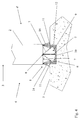
- FIG. 1 shows a cross-sectional view of a sill and opening-leaf assembly according to the present invention, with a flexible gasket element and a dust-guard brush, when said element is in the idle state, which lies in a vertical mid-plane at the bottom of the groove,
- FIG. 2 shows the sill and opening-leaf assembly of FIG. 1 , in a first alternative embodiment of the groove
- FIG. 3 shows the sill and opening-leaf assembly of FIG. 1 , in a second alternative embodiment of the groove, with two dust-guard brushes,
- FIG. 4 shows the sill and opening-leaf assembly of FIG. 3 , which, by means of dashed lines, shows two travel limit positions of the gasket element inside the groove,
- FIG. 5 shows the sill and opening-leaf assembly of FIG. 1 , in a third alternative embodiment of the groove
- FIG. 6 shows a cross-sectional view of a sill and opening-leaf assembly according to the present invention, with a hinged gasket element and two dust-guard brushes, which, by means of dashed lines, shows two travel limit positions of the gasket element inside the groove, starting from the vertical idle position thereof.
- the figures show a sill 1 and opening leaf 2 assembly for a door that is essentially fluid-tight to a liquid or gaseous fluid and intended to seal an opening 3 separating two spaces 4 , 4 ′ of a building or monument, including an opening leaf 2 of which one of the edge faces or lower edge face 6 is situated, when mounted, facing a floor surface 5 , and a sill 1 able to provide fluid-tightness, with respect to said fluid, of the bottom part of the door concerned, i.e., the empty space situated between the lower edge face 6 and said floor surface 5 .
- such a sill 1 firstly comprises at least one flat and elongate gasket element 7 of the tongue type, which comprises a front longitudinal surface and a rear longitudinal surface, and which is attached via one of its longitudinal sides or longitudinal attachment side 8 to said lower edge face 6 and, secondly, comprises at a sealing and travel groove 9 , comprising a bottom 10 and two longitudinal edges 11 , which is made in said floor surface 5 across the opening 3 concerned and intended to receive the gasket element 7 .
- the gasket element 7 when mounted, is able to engage with either of said longitudinal edges 11 , by being allowed to travel into said groove 9 , depending on whether a pressure force is exerted by a liquid or gaseous fluid from one of said spaces 4 or 4 ′ on the front longitudinal surface or rear longitudinal surface of said gasket element 7 , so as to ensure the fluid-tightness of the bottom part of said door concerned, between said lower edge face 6 and said floor surface 5 .
- the gasket element 7 can be flexible or soft, at least on the longitudinal side 8 thereof, which is attached to the lower edge face 6 of the opening leaf 2 , so as to allow it [said gasket element] a freedom of movement, by elastically deforming and bending around said longitudinal attachment side 8 , in the groove 9 , between the two longitudinal edges 11 thereof ( FIGS. 1 to 5 ).
- the gasket element 7 can be flexible or soft on the longitudinal side 8 thereof or over all or part of the width thereof, including said longitudinal side 8 .
- the gasket element 7 can be rigid, semi-rigid or flexible, and pivotably mounted via the longitudinal attachment side 8 thereof, by means of a hinge-type pin joint, about a swivel pin 15 extending along the lower edge face 6 , so as to allow the gasket element 7 a freedom of travel, by rotating about said swivel pin 15 , inside the groove 9 between the longitudinal edges 11 thereof ( FIG. 6 ).
- the longitudinal edges 11 of the groove 9 can preferably each form a right angle with the floor surface 5 ( FIGS. 2 and 5 ). Alternatively, they can likewise each be inclined toward the bottom 10 of the groove 9 ( FIGS. 1 , 3 , 4 and 6 ). This is done so that each longitudinal edge 11 forms a longitudinal abutment enabling the gasket 7 to be retained inside the groove 9 when a pressure force is exerted by the liquid or gaseous fluid on the front longitudinal surface or rear longitudinal surface of said gasket element ( FIGS. 4 to 6 ).
- such a groove 9 can have an overall U-shaped cross-section ( FIGS. 2 and 5 ) or dovetail-shaped cross-section ( FIGS. 1 , 3 , 4 and 6 ), preferably with a flat bottom ( FIGS. 2 and 5 ) or an arc of circle-shaped bottom ( FIGS. 1 , 3 , 4 and 6 ).
- the groove 9 can be made in an insert 12 embedded in the floor surface 5 (figures).
- the present invention can advantageously further provide for a protective dust-guard system 13 or 14 extending longitudinally on either side of the gasket element 7 , so as to prevent the dust from either of the two spaces 4 or 4 ′ separated by the door opening 3 , respectively, from reaching the groove 9 and, in particular, from accumulating therein.
- same can consist of an elongate dust-guard brush 13 that can be attached to the lower edge face 6 of the opening leave 2 , where the gasket element 7 is attached, and which can comprise two dust-guard brush portions 13 extending on either side of the gasket element 7 , as far as the corresponding floor surface 5 , and each forming a protective guard against the dust from one of the two spaces 4 or 4 ′, respectively ( FIGS. 1 , 2 and 5 ).
- same can consist of two dust-guard brushes 14 each attached to the lower edge face 6 of the opening leaf 2 , on either side of and separately from the gasket element 7 , said dust-guard brushes 14 each extending as far as the corresponding floor surface 5 ( FIGS. 3 , 4 and 6 ), so that each forms a protective guard against the dust from one of the two spaces 4 or 4 ′, respectively.
- the or each dust-guard brush 13 or 14 can be made from natural, synthetic or metal bristles, which, at one of the ends thereof, are pressed into a support strip attached to or built into the lower edge face 6 .
- the present invention can advantageously provide for the bottom 10 of the groove 9 to comprise at least one cavity 16 for receiving dust, preferably two receiving cavities 16 , which are made on either side of a mid-plane at said bottom 10 and, more preferably, for the or each receiving cavity 16 , at the base of the corresponding longitudinal edge 11 , so as to be able to recover the dust accumulated in the bottom 10 when the door is opened, i.e., without any protective guards 13 or 14 for the groove 9 .
- the dust thus accumulated in the bottom 10 can then be pushed or swept into the receiving cavity or cavities 16 , when the door is closed, by the movement of the gasket element 7 inserted into the groove 9 ( FIG. 1 ).
Landscapes
- Engineering & Computer Science (AREA)
- Civil Engineering (AREA)
- Structural Engineering (AREA)
- Specific Sealing Or Ventilating Devices For Doors And Windows (AREA)
Abstract
Description
Claims (17)
Applications Claiming Priority (1)
| Application Number | Priority Date | Filing Date | Title |
|---|---|---|---|
| PCT/FR2010/051955 WO2012038608A1 (en) | 2010-09-20 | 2010-09-20 | Sill and opening-leaf assembly for a door that essentially is fluid-tight to a liquid or gaseous fluid and is intended to seal an opening separating two spaces in a building or monument |
Publications (2)
| Publication Number | Publication Date |
|---|---|
| US20140173992A1 US20140173992A1 (en) | 2014-06-26 |
| US8919044B2 true US8919044B2 (en) | 2014-12-30 |
Family
ID=43086454
Family Applications (1)
| Application Number | Title | Priority Date | Filing Date |
|---|---|---|---|
| US13/825,151 Expired - Fee Related US8919044B2 (en) | 2010-09-20 | 2010-09-20 | Sill and opening-leaf assembly for a door that essentially is fluid-tight to a liquid or gaseous fluid and is intended to seal an opening separating two spaces in a building or monument |
Country Status (4)
| Country | Link |
|---|---|
| US (1) | US8919044B2 (en) |
| EP (1) | EP2619394B1 (en) |
| SI (1) | SI2619394T1 (en) |
| WO (1) | WO2012038608A1 (en) |
Cited By (2)
| Publication number | Priority date | Publication date | Assignee | Title |
|---|---|---|---|---|
| US20210102352A1 (en) * | 2017-03-30 | 2021-04-08 | Steen Olsen Invest Aps | Flood Protection |
| USD1063109S1 (en) * | 2024-04-23 | 2025-02-18 | Guoqing XU | Door stopper for bottom of door |
Families Citing this family (3)
| Publication number | Priority date | Publication date | Assignee | Title |
|---|---|---|---|---|
| US10100573B2 (en) * | 2014-09-08 | 2018-10-16 | Clean Energy Fuels Corp. | Natural gas vehicle maintenance separation and containment system |
| GB2581995B (en) * | 2019-03-06 | 2021-08-04 | Trieste Group One Ltd | A booth |
| US11952833B1 (en) * | 2019-09-11 | 2024-04-09 | Larson Manufacturing Company Of South Dakota, Llc | Building systems and methods for installing building systems relative to building openings |
Citations (12)
| Publication number | Priority date | Publication date | Assignee | Title |
|---|---|---|---|---|
| US2055512A (en) * | 1935-02-25 | 1936-09-29 | Galen A Wallace | Sluice gate seal |
| US2568477A (en) * | 1949-01-31 | 1951-09-18 | Jesse V Westlund | Door check |
| US2579875A (en) * | 1950-05-20 | 1951-12-25 | Stanko Lloyd | Door threshold |
| US5150544A (en) * | 1991-08-28 | 1992-09-29 | Schlegel Corporation | Magnetically mounted door sweep |
| US5174065A (en) * | 1992-01-08 | 1992-12-29 | The Stanley Works | Door sweep with face sealing element |
| US5214880A (en) * | 1992-04-03 | 1993-06-01 | Emco Enterprises, Inc. | Door edge construction |
| US5706607A (en) * | 1994-09-17 | 1998-01-13 | Frey; Harry | Magnetic door seal |
| GB2333797A (en) | 1998-01-30 | 1999-08-04 | Eskimo Architectural Products | Extendable sill arrangement |
| DE19841180A1 (en) | 1998-09-09 | 2000-03-23 | Peter Willrich | Door shrouding profile against rain and spray water has a guide to take an optic fiber cable to provide illumination over the doorstep area |
| US6061967A (en) * | 1999-01-19 | 2000-05-16 | Judds; Raymond E. | Overhead door sealing assembly |
| US7644539B2 (en) * | 2005-06-21 | 2010-01-12 | Stephen Marshall Baxter | Automatic door bottom and sill assemblage |
| US20100064590A1 (en) * | 2008-09-12 | 2010-03-18 | La Cantina Doors, Inc. | Zero step sill extruded flush threshold door seal system |
-
2010
- 2010-09-20 EP EP20100771495 patent/EP2619394B1/en not_active Not-in-force
- 2010-09-20 WO PCT/FR2010/051955 patent/WO2012038608A1/en not_active Ceased
- 2010-09-20 SI SI201031002T patent/SI2619394T1/en unknown
- 2010-09-20 US US13/825,151 patent/US8919044B2/en not_active Expired - Fee Related
Patent Citations (12)
| Publication number | Priority date | Publication date | Assignee | Title |
|---|---|---|---|---|
| US2055512A (en) * | 1935-02-25 | 1936-09-29 | Galen A Wallace | Sluice gate seal |
| US2568477A (en) * | 1949-01-31 | 1951-09-18 | Jesse V Westlund | Door check |
| US2579875A (en) * | 1950-05-20 | 1951-12-25 | Stanko Lloyd | Door threshold |
| US5150544A (en) * | 1991-08-28 | 1992-09-29 | Schlegel Corporation | Magnetically mounted door sweep |
| US5174065A (en) * | 1992-01-08 | 1992-12-29 | The Stanley Works | Door sweep with face sealing element |
| US5214880A (en) * | 1992-04-03 | 1993-06-01 | Emco Enterprises, Inc. | Door edge construction |
| US5706607A (en) * | 1994-09-17 | 1998-01-13 | Frey; Harry | Magnetic door seal |
| GB2333797A (en) | 1998-01-30 | 1999-08-04 | Eskimo Architectural Products | Extendable sill arrangement |
| DE19841180A1 (en) | 1998-09-09 | 2000-03-23 | Peter Willrich | Door shrouding profile against rain and spray water has a guide to take an optic fiber cable to provide illumination over the doorstep area |
| US6061967A (en) * | 1999-01-19 | 2000-05-16 | Judds; Raymond E. | Overhead door sealing assembly |
| US7644539B2 (en) * | 2005-06-21 | 2010-01-12 | Stephen Marshall Baxter | Automatic door bottom and sill assemblage |
| US20100064590A1 (en) * | 2008-09-12 | 2010-03-18 | La Cantina Doors, Inc. | Zero step sill extruded flush threshold door seal system |
Non-Patent Citations (1)
| Title |
|---|
| International Search Report issued in corresponding application No. PCT/FR2010/051955 mailed Mar. 21, 2011. |
Cited By (3)
| Publication number | Priority date | Publication date | Assignee | Title |
|---|---|---|---|---|
| US20210102352A1 (en) * | 2017-03-30 | 2021-04-08 | Steen Olsen Invest Aps | Flood Protection |
| US11629469B2 (en) * | 2017-03-30 | 2023-04-18 | Steen Olsen Invest Aps | Flood protection |
| USD1063109S1 (en) * | 2024-04-23 | 2025-02-18 | Guoqing XU | Door stopper for bottom of door |
Also Published As
| Publication number | Publication date |
|---|---|
| EP2619394B1 (en) | 2015-05-20 |
| EP2619394A1 (en) | 2013-07-31 |
| SI2619394T1 (en) | 2015-10-30 |
| US20140173992A1 (en) | 2014-06-26 |
| WO2012038608A1 (en) | 2012-03-29 |
Similar Documents
| Publication | Publication Date | Title |
|---|---|---|
| US8919044B2 (en) | Sill and opening-leaf assembly for a door that essentially is fluid-tight to a liquid or gaseous fluid and is intended to seal an opening separating two spaces in a building or monument | |
| CA2583959C (en) | Entry system with water infiltration barrier | |
| CA2192005C (en) | Rolling door made from interlocking thermoplastic panels | |
| US3941180A (en) | Sectional door and guard rail assembly | |
| US8739469B1 (en) | Protective cover | |
| US5718276A (en) | Thermoplastic interlocking panels | |
| EP2687665A1 (en) | Hidden rail type window and door system | |
| US10190310B2 (en) | Waterproof storage unit | |
| US20140027074A1 (en) | Safety screen frame | |
| KR101999086B1 (en) | Built-in rail sliding window | |
| EP0850344A1 (en) | Lift gate | |
| KR200470050Y1 (en) | Windshield device for sash | |
| KR200468255Y1 (en) | Balustrade system for preventing accident falling | |
| EP1476629B1 (en) | Combined weather seal, light block and wear insert for overhead door panel | |
| KR20140036442A (en) | Filling piece for sliding windows | |
| KR101321711B1 (en) | Sealant For Sliding Door | |
| US20070227074A1 (en) | Enclosed sliding door assembly | |
| US20160167498A1 (en) | Vehicle Cover | |
| KR200476849Y1 (en) | Guide rail shutter for reinforced windproof function | |
| ES2844251T3 (en) | Floor covering for a people transport device | |
| US20040040214A1 (en) | Door-mounted bug barrier apparatus | |
| CN213799628U (en) | Hanging carriage for sightseeing cable car in scenic spot | |
| US20220072939A1 (en) | System and method of tailgate to truck bed sealing to prevent debris from falling into and lodging in a gap between a tailgate and a truck bed | |
| US20050183834A1 (en) | Hinge assembly | |
| EP2845984B1 (en) | Heel intended for being connected with a casing for holding the mechanism of a roller shutter |
Legal Events
| Date | Code | Title | Description |
|---|---|---|---|
| AS | Assignment |
Owner name: BAUMERT TECHNOLOGIES, FRANCE Free format text: ASSIGNMENT OF ASSIGNORS INTEREST;ASSIGNOR:BAUMERT, BERNARD;REEL/FRAME:030220/0383 Effective date: 20130328 Owner name: BAUMERT, FRANCE Free format text: CHANGE OF NAME;ASSIGNOR:BAUMERT TECHNOLOGIES;REEL/FRAME:030220/0516 Effective date: 20070403 |
|
| AS | Assignment |
Owner name: BAUMERT, FRANCE Free format text: CHANGE OF NAME;ASSIGNOR:BAUMERT TECHNOLOGIES;REEL/FRAME:030452/0773 Effective date: 20070403 |
|
| STCF | Information on status: patent grant |
Free format text: PATENTED CASE |
|
| MAFP | Maintenance fee payment |
Free format text: PAYMENT OF MAINTENANCE FEE, 4TH YEAR, LARGE ENTITY (ORIGINAL EVENT CODE: M1551) Year of fee payment: 4 |
|
| FEPP | Fee payment procedure |
Free format text: MAINTENANCE FEE REMINDER MAILED (ORIGINAL EVENT CODE: REM.); ENTITY STATUS OF PATENT OWNER: LARGE ENTITY |
|
| LAPS | Lapse for failure to pay maintenance fees |
Free format text: PATENT EXPIRED FOR FAILURE TO PAY MAINTENANCE FEES (ORIGINAL EVENT CODE: EXP.); ENTITY STATUS OF PATENT OWNER: LARGE ENTITY |
|
| STCH | Information on status: patent discontinuation |
Free format text: PATENT EXPIRED DUE TO NONPAYMENT OF MAINTENANCE FEES UNDER 37 CFR 1.362 |
|
| FP | Lapsed due to failure to pay maintenance fee |
Effective date: 20221230 |