US891798A - Cotton-gin. - Google Patents
Cotton-gin. Download PDFInfo
- Publication number
- US891798A US891798A US58024696A US1896580246A US891798A US 891798 A US891798 A US 891798A US 58024696 A US58024696 A US 58024696A US 1896580246 A US1896580246 A US 1896580246A US 891798 A US891798 A US 891798A
- Authority
- US
- United States
- Prior art keywords
- breast
- rolls
- gin
- seed
- rollers
- Prior art date
- Legal status (The legal status is an assumption and is not a legal conclusion. Google has not performed a legal analysis and makes no representation as to the accuracy of the status listed.)
- Expired - Lifetime
Links
Images

Classifications
-
- D—TEXTILES; PAPER
- D01—NATURAL OR MAN-MADE THREADS OR FIBRES; SPINNING
- D01B—MECHANICAL TREATMENT OF NATURAL FIBROUS OR FILAMENTARY MATERIAL TO OBTAIN FIBRES OF FILAMENTS, e.g. FOR SPINNING
- D01B1/00—Mechanical separation of fibres from plant material, e.g. seeds, leaves, stalks
- D01B1/02—Separating vegetable fibres from seeds, e.g. cotton
- D01B1/04—Ginning
Definitions
- his invention relates to that class or' cot-4 ton gine in which a breast formed ot arallel slats is used, the intervals between t elslats being smaller than the size of a cotton seed.
- my invention propose instead or" the saws to use two rollers engaging together upon the side of the breast away lloro the side from which the bolls are fed.
- One or both of these rollers is lluted so to admit ci air passing through their point of juncture.
- An air blast is generated.
- troni a fan or by means of the rollers acting as fans, and the sta le Will be blown through the interstices of t e breast, and will be nipped between the tWo faces of the rollers Where it will be pulled until the seed is forced up against the slats of the breast, when .the staple wl become disengaged aud the seed will drop away troni the breast.
- the rollers may also be introduced .in 'further byproviding the faces the rollers with parallel slits extending in troni their depth equal to the thickness of the breast'.
- the apex ol the breast nia-3i' then be introduced between the rollers through 'these slits, when the inner the breast will be found to be coincident with the noints of contact of the rollers.
- Y is a gin using belts in engagement;
- Fig. 8 -a section of a gin showing the of 'the rollers mounted in the saine horizontal planewitli the breast above and
- FigfQ is a View of the saine, showing the breast below.
- rollers represent a l'luted roller' 2, n solid roller Ver much smaller in size. rollers are rougliened or covert.. l with a rough substance in order to properly nip the staple, ann both provided with pziirallel lf3 their circuinierernre. roner l gated as shown, lorn'unD four Wi t 3, 3.
- the bells being fed in at 7 will be drawn by the current of air caused by the rapid revolution of the rollers in the direction ci tue arrows between the slats of the breast.
- the staple will then be nipped lietsifeen the face of the roller 1 and the outer circumference of the roller 2, and will draw the seed up against the apex of-t Kunststoffreast 5, when the liber-s will be broken oli.
- the staple will then be car ried out and removed by the brush le in the direction ci the point ci t 'it 1g l0 serres to support thi. and maintain ust the peripheries to a one rol ⁇ n only provided with Qld liti
- V from the seen, the latter will drop by gravity y from the point 5, into a receptacle 9, behind y dependently and below the breast, the draft of air being regulated so that it will have sufficient force to lift up a boll and draw the staple through the breast, but will'not be strong enough to hold. up a ginned seed.
- the entire breast or avportion of it may be arranged to be momentarily drawn away from. its normal position to the position shown in broken lines ef Fig. 1.
- a convenient means for effecting this movement is shown.
- the breast is pivoted at 11 and is connected a short distance above the point of pivoting, with la rod 12, to a cam 13, on one of the revolving members of the gin; in the illustration to the shaft of the inner roll of thefeed a ron.
- the rolls may be either positively driven by direct connections, or theA construction illustrated may be employed.
- the roll 1 is positively driven.
- a balance wheel 17 serving to give uniformity to the movements of the second roll.
- Fig. 3 represents a gin fluted and of equal diameter, tating at the same rate The cotton is fed in the apex of the breast and the fiber or staple is drawn through.
- Fig. 4 is a gin showing both rolls solid, the blast of air being generated by a fan as shown.
- Fig. 5 shows a gin the lower roll of which is grooved for receiving the bars of the having both rolls both rolls roy breast.
- disks are secured to a common shaft. These disks may be either plain or fluted as shown.
- FIG. 47 Another form of gin is shown in Fig. 47, wherein moving belts are used to grasp and carry away the staple.
- a gin is shown with the axes of zontal plane.
- the breast is above or both may be plain, the air blast being ingenerated, the air passing through the interstices between the rolls; only one or neither may be peripherally slitted; or they may be formed of a number of disks secured to a common spindle; or two engaging moving belts or other surfaces may be em loyed in lieu of rolls.
- the breast may e immovably secured to the frame of the gin, or it may be rapidly oscillated or shaken to assist in removing the staple, the relative position of the rolls may be varied, as for instance they may both be on the same horizontal or vertical plane, with the breast either below or above them.
- the combination with an angular breast having openings therein of smaller diameter than the seed, of two oppositely revolving rolls engaging together adjacent to the apex of said breast, and means for generating a blast of air through said breast and between said rolls, whereby staple will be drawn through the o enings in said breast and will be engaged etween said rolls and thereby be separated from seed.
- the combination withtwo oppositely revolving rolls said rolls being fluted to form' radial wings, the eripheries of which engage together, the said wings serving to generate a blast of air, of an angular' breast, having openings of smaller diameter thanI ythe seed, the internal apex of which is adjacent to the pinching faces of said rolls.
Description
N0. 891,798, Y PATENTE JUNE 2s, 190s. L. H. DYBR. COTTON GIN.
APPLGATION `IILBD PEB. 21, 1898.
z SHEETS-SHEET 1.v
jay. j
lllllzll/lll/lI/llflll/llrl/lIl/l//lllll/lll No. 891,798.- l PATENTE) JUNE 23. 1908.
L. H. DYER.
GOTTON GIN.
APPLICATION FILED FEB. 21, 1896.
2 SHEETS-SHEET 2.
j@ 0" Jig. 9
V Witnesses. .j Inventor Attorney.
nrrnn f i. @einem Pil.. in.- a .i
l corren-ern.
To all whom 'it' may con/cera:
t'Be it known that l, LroinirnoV 'lUNTaEss DYER, a citizen of the United States, residing at Washington, in the District of Columbia, have invented certain new and useful lmprovements in Cotton-Cons; and l do .hereby declare the following to be a full, clear, and exact description of the invention, which Will enable others skilled in the art to which it appertains to make and use the saine.
his invention relates to that class or' cot-4 ton gine in which a breast formed ot arallel slats is used, the intervals between t elslats being smaller than the size of a cotton seed.
In the usual style of sauT gin, the teeth of the sawspass through the breast .and project beyond the other side thereof and engage With the staple, pulling it through the interstices and breaking it away from the seed..
There has always been objection to this type of gin, as the saws greatly damage the staple,
.breaking it into short lengths before entirely detaching it lirontl the seat. Furthermore the area of Working surface is small cornpared to the size of the machine, as 'the teeth must enter a loop of the staple before stripping it jfrom the seat.
In my invention I propose instead or" the saws to use two rollers engaging together upon the side of the breast away lloro the side from which the bolls are fed. One or both of these rollers is lluted so to admit ci air passing through their point of juncture. An air blast is generated. troni a fan or by means of the rollers acting as fans, and the sta le Will be blown through the interstices of t e breast, and will be nipped between the tWo faces of the rollers Where it will be pulled until the seed is forced up against the slats of the breast, when .the staple wl become disengaged aud the seed will drop away troni the breast.
In order to allow the insidei'ace of the breast to be located as close as possible to the point of contact of the rollers, l make it in the forni of a riglitangle, the acute apex of which is introduced between the rollers. As the breast must be of seine considerable 'thickness in order to secure the requisite amount of strength, the inner part of vrthe apex Will still be some distance from the point of contact of the rollers. ln order to get the apex still further in, l niay ineke one roller much smaller niake the angle of both rollers Were the saine size.
Specification of Lettere Era-tentv Application led February 2]., X896.
June 160:25. Serial No. ittflf.
may also be introduced .in 'further byproviding the faces the rollers with parallel slits extending in troni their depth equal to the thickness of the breast'. The apex ol the breast nia-3i' then be introduced between the rollers through 'these slits, when the inner the breast will be found to be coincident with the noints of contact of the rollers. n
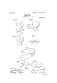
In order to better understand ot rny invention attention is called to companying drawings Whichz-- Figure l, is an end View patly of the Working parts of a gin embodying my invention and Fig. 2, viront `View or the rollers and breast with the brush removed; Fig. 3, is a section of the rollers and breast of the gin, both rollers being of equal size and being lluted; Fig. 4l, is a section of the roller of a gin, showing both rollers solid Without flutes and with a ian 'to generating an independent blast of air; F 5, is a section of in sectie grooves F ig. is section of a .roller formed oi a number of independent disks; Fig. Y, is a gin using belts in engagement; Fig. 8, -a section of a gin showing the of 'the rollers mounted in the saine horizontal planewitli the breast above and FigfQ, is a View of the saine, showing the breast below.
In all oi the Views lik parte do by the seine numerals ot reference,
l represents a l'luted roller' 2, n solid roller Ver much smaller in size. rollers are rougliened or covert.. l with a rough substance in order to properly nip the staple, ann both provided with pziirallel lf3 their circuinierernre. roner l gated as shown, lorn'unD four Wi t 3, 3. The breast 1s shown et Ll og at an acute angle at 5, within short distance ol' the point ci contact of the two rollers at G. The bells being fed in at 7 will be drawn by the current of air caused by the rapid revolution of the rollers in the direction ci tue arrows between the slats of the breast. The staple will then be nipped lietsifeen the face of the roller 1 and the outer circumference of the roller 2, and will draw the seed up against the apex of-tliebreast 5, when the liber-s will be broken oli. The staple will then be car ried out and removed by the brush le in the direction ci the point ci t 'it 1g l0 serres to support thi. and maintain ust the peripheries to a one rol` n only provided with Qld liti
V,from the seen, the latter will drop by gravity y from the point 5, into a receptacle 9, behind y dependently and below the breast, the draft of air being regulated so that it will have sufficient force to lift up a boll and draw the staple through the breast, but will'not be strong enough to hold. up a ginned seed.
In ease there should be difficulty in removing the seed from the apex of the breast, the entire breast or avportion of it may be arranged to be momentarily drawn away from. its normal position to the position shown in broken lines ef Fig. 1. A convenient means for effecting this movement is shown. The breast is pivoted at 11 and is connected a short distance above the point of pivoting, with la rod 12, to a cam 13, on one of the revolving members of the gin; in the illustration to the shaft of the inner roll of thefeed a ron. This movement-will, completely free t e seed from all engagement with the rolls, and will allow them to drop downwards into the receptacle for their use.
In operating the gin, the rolls may be either positively driven by direct connections, or theA construction illustrated may be employed.
In this case the roll 1 is positively driven.
from some external source of power, while the roll 2 receives motion by engaging with the first roll; a balance wheel 17 serving to give uniformity to the movements of the second roll.
Fig. 3 represents a gin fluted and of equal diameter, tating at the same rate The cotton is fed in the apex of the breast and the fiber or staple is drawn through.
Fig. 4, is a gin showing both rolls solid, the blast of air being generated by a fan as shown.
Fig. 5, shows a gin the lower roll of which is grooved for receiving the bars of the having both rolls both rolls roy breast.
In the roller shown in Fig. 6, the disks are secured to a common shaft. These disks may be either plain or fluted as shown.
Another form of gin is shown in Fig. 47, wherein moving belts are used to grasp and carry away the staple.-
In' Figs. 8 and 9, a gin is shown with the axes of zontal plane. the roll, the sta le passing down by means o gravity, and in ig. 9, the breast is below the rolls and the cotton is blpwn upwardl.
Before claiming my invention I 'desire to f have it understood that I do not limit myself to the precise construction illustrated, as many of the elements shown may be changed o1` entirely eliminated without departing from the'y essence of my invention, (which is the employment of a breast with two moving surfaces engaging together, adjacent thereto as for instance, both rolls ma be of the same size or approximately so bot i may be fluted of speed as shown.
he rolls mounted on the same hori- In Fig. 8 the breast is above or both may be plain, the air blast being ingenerated, the air passing through the interstices between the rolls; only one or neither may be peripherally slitted; or they may be formed of a number of disks secured to a common spindle; or two engaging moving belts or other surfaces may be em loyed in lieu of rolls. The breast may e immovably secured to the frame of the gin, or it may be rapidly oscillated or shaken to assist in removing the staple, the relative position of the rolls may be varied, as for instance they may both be on the same horizontal or vertical plane, with the breast either below or above them. Some other means than gravity may be employed for removing the ginned seed, the
brush may be dispensed with, and the lintv removed by centrifugal action and it is also obvious that any number of elements may be combined together in one gin.
In accordance with the provisions of the patent statutes, I have described the rineiple of my invention, together with t e apparatus which I now consider to represent the best embodiment thereof, but I desire to have it understood that the ap aratus shown is merely illustrative and t at the invention can oe-carried out .in other ways.
Having now described my invention what I claim as new therein and desire to secure by' Letters Patent is as follows 1. In a gin, the combination with an an ular breast, having openings therein of smal er diameter than the seed, of two oppositely revolving rolls with'their peri heral faces engagin 'together adjacent to tlie internal apex of sai breast, whereby staplepassing through the openings in said breast will be engaged between said rolls and thereby be separated from seed.
2. In a gin, the combination with an angular breast, having openings therein of smaller diameter than the seed, of two oppositely revolving rolls engaging together adjacent to the apex of said breast, and means for generating a blast of air through said breast and between said rolls, whereby staple will be drawn through the o enings in said breast and will be engaged etween said rolls and thereby be separated from seed.
3. In a gin, the combination withtwo oppositely revolving rolls, said rolls being fluted to form' radial wings, the eripheries of which engage together, the said wings serving to generate a blast of air, of an angular' breast, having openings of smaller diameter thanI ythe seed, the internal apex of which is adjacent to the pinching faces of said rolls.
4. Inv a gin, the combination with two 0ppositely revolving rolls, the peripheries of which engage together, one-at least of said rolls being lluted to form radial wings, of an angular breast, having openings therein of smaller diam` ter than the seed, the internal lli) vpositely revolving rolls, the peripheries of 4than the seed, the
apex ofl which is faces of said rolls. 5. In a gin, the combination with two opy positely revolving rolls, the peripheries of! which engage together, s'aid rolls being periphera'lly grooved, of an an ular breast, having openlngs therein of smal er diameter than I positely revolving rolls engaging together, of the seed, the internalapex of which enters l an angular breast, having openings therein said grooves and is adjacent to the pinching j of smaller' diameter than the seed, the apex faces of the rolls. of the said breast being adjacent to the pinch- 6. In a gin, the combination with two oping faces of the rolls.
adjacent to the pinching l of said rolls with its internal a eX adjacent to the pinching faces thereof, wlifereby staple will be drawn through the openings in said breast and will be engaged between the said l rolls and thereby be separated from seed.
9. In a gin, the combination with two opwhich engage together, one of said rolls being positely revolving rolls engaging together, of eripherally grooved, .of an angular breast, an angular breast having openings therein of aving openings therein of sma ler diameter smaller diameter than the seed, the internal than the seed, the internal apex of which apex ofthe said breast being adjacent to the enters said grooves and is adjacent' to the pinching faces of the rolls. c pinching faces of the rolls. t 11. In a. gin, the combination with an angu- 7. In a gin, the combination with two op- ,l lar breast, of a pair of rolls with their periphpositely revolving rolls, the peri heri'es of l eral faces engaging together, the point ofenwhich engage together, of an an fu ar breast, ifagement being sufficientlyV near to the inhaving openings therein of smal er diameter ,l ternal apex of the breast, to permit staple internal apex of which is l being drawn through the interstices of the adjacent to the pinching faces of the rolls, l breast by the action of the rolls and thereby and means for intermittently retracting and be separated from the seed,tsubstantially as advancing the breast from the rolls. set forth. g f
8. In a in, the combination with an angu- This specification signed and lar breast aving openings therein of smaller I this 21st day of February v1896. diameter than the seed, of two oppositely re- LEONARD llliNv'llt ESS DYER. Volving rolls engaging together, said rolls Witnesses: being both laterally fluted and peripherally FRANK li. D YER, grcoved, the said breast entering the grooves witnessed j L. DELLA McGmR,
10. In a gin, the combination with two op-
Priority Applications (1)
| Application Number | Priority Date | Filing Date | Title |
|---|---|---|---|
| US58024696A US891798A (en) | 1896-02-21 | 1896-02-21 | Cotton-gin. |
Applications Claiming Priority (1)
| Application Number | Priority Date | Filing Date | Title |
|---|---|---|---|
| US58024696A US891798A (en) | 1896-02-21 | 1896-02-21 | Cotton-gin. |
Publications (1)
| Publication Number | Publication Date |
|---|---|
| US891798A true US891798A (en) | 1908-06-23 |
Family
ID=2960229
Family Applications (1)
| Application Number | Title | Priority Date | Filing Date |
|---|---|---|---|
| US58024696A Expired - Lifetime US891798A (en) | 1896-02-21 | 1896-02-21 | Cotton-gin. |
Country Status (1)
| Country | Link |
|---|---|
| US (1) | US891798A (en) |
-
1896
- 1896-02-21 US US58024696A patent/US891798A/en not_active Expired - Lifetime
Similar Documents
| Publication | Publication Date | Title |
|---|---|---|
| US4060966A (en) | Apparatus for spinning textile fibers | |
| US20220042205A1 (en) | Device and method for transferring cotton fiber, and device for removing impurity in cotton fiber | |
| US2014673A (en) | Carding cleaning, opening, and like machine for textile fibers | |
| US1401439A (en) | Lint-cotton-treating machine | |
| US891798A (en) | Cotton-gin. | |
| US1751306A (en) | Cotton gin | |
| GB963053A (en) | Apparatus for cleaning textile fibrous material | |
| US732869A (en) | Cotton huller, cleaner, and gin-feeder. | |
| US373075A (en) | And cleaning cotton | |
| RU2785538C1 (en) | Disintegrator-cleaner of fibrous materials | |
| CN110938873A (en) | Negative pressure-preventing high-efficiency diversion cotton ginning device | |
| US565793A (en) | pollard | |
| CN110172738A (en) | Gined cotton carding apparatus and institute's application apparatus | |
| US1630005A (en) | Gin | |
| US1751308A (en) | Cotton-gin machinery | |
| US2228619A (en) | Cotton ginning method and apparatus | |
| US2977641A (en) | Lint cotton opener and cleaner | |
| US961393A (en) | Cotton-ginning machinery. | |
| US1396142A (en) | Hulling and cleaning feeder for cotton-gins | |
| US2736068A (en) | Trash removing means for cotton gins | |
| US2637075A (en) | Cotton lint conditioning machine | |
| US106700A (en) | Emile lefeanc and joseph nagoija | |
| US3952493A (en) | Apparatus for ringless spinning of fibers | |
| US1740439A (en) | Appliance for opening fiber bundles | |
| US1273182A (en) | Attachment for huller-gins. |