US8917787B2 - Systems and methods for creating a downlink precode for communication system with per-antenna power constraints - Google Patents
Systems and methods for creating a downlink precode for communication system with per-antenna power constraints Download PDFInfo
- Publication number
- US8917787B2 US8917787B2 US13/069,093 US201113069093A US8917787B2 US 8917787 B2 US8917787 B2 US 8917787B2 US 201113069093 A US201113069093 A US 201113069093A US 8917787 B2 US8917787 B2 US 8917787B2
- Authority
- US
- United States
- Prior art keywords
- phase
- matrix
- transmitter
- antenna
- receiver
- Prior art date
- Legal status (The legal status is an assumption and is not a legal conclusion. Google has not performed a legal analysis and makes no representation as to the accuracy of the status listed.)
- Expired - Fee Related, expires
Links
Images


Classifications
-
- H—ELECTRICITY
- H04—ELECTRIC COMMUNICATION TECHNIQUE
- H04B—TRANSMISSION
- H04B7/00—Radio transmission systems, i.e. using radiation field
- H04B7/02—Diversity systems; Multi-antenna system, i.e. transmission or reception using multiple antennas
- H04B7/04—Diversity systems; Multi-antenna system, i.e. transmission or reception using multiple antennas using two or more spaced independent antennas
- H04B7/0413—MIMO systems
- H04B7/0426—Power distribution
- H04B7/0434—Power distribution using multiple eigenmodes
- H04B7/0447—Power distribution using multiple eigenmodes utilizing uniform distribution
-
- H—ELECTRICITY
- H04—ELECTRIC COMMUNICATION TECHNIQUE
- H04B—TRANSMISSION
- H04B7/00—Radio transmission systems, i.e. using radiation field
- H04B7/02—Diversity systems; Multi-antenna system, i.e. transmission or reception using multiple antennas
- H04B7/04—Diversity systems; Multi-antenna system, i.e. transmission or reception using multiple antennas using two or more spaced independent antennas
- H04B7/0413—MIMO systems
- H04B7/0426—Power distribution
-
- H—ELECTRICITY
- H04—ELECTRIC COMMUNICATION TECHNIQUE
- H04B—TRANSMISSION
- H04B7/00—Radio transmission systems, i.e. using radiation field
- H04B7/02—Diversity systems; Multi-antenna system, i.e. transmission or reception using multiple antennas
- H04B7/04—Diversity systems; Multi-antenna system, i.e. transmission or reception using multiple antennas using two or more spaced independent antennas
- H04B7/0413—MIMO systems
- H04B7/0456—Selection of precoding matrices or codebooks, e.g. using matrices antenna weighting
- H04B7/046—Selection of precoding matrices or codebooks, e.g. using matrices antenna weighting taking physical layer constraints into account
- H04B7/0465—Selection of precoding matrices or codebooks, e.g. using matrices antenna weighting taking physical layer constraints into account taking power constraints at power amplifier or emission constraints, e.g. constant modulus, into account
Definitions
- the present application is directed generally towards communication systems, and more specifically towards creating a downlink precode filter for communication systems with per-antenna power constraints.
- MIMO Multiple Input Multiple Output
- optimal capacity is typically achieved using the well known ‘Water-filling’ solution.
- This practice achieves optimal channel capacity by distributing total available transmit power to transmit antennas according to the Water-filling solution. Usually, this results in unequal power distribution among different transmit antennas and doesn't guarantee that allocated power is within the linear range of the power amplifier associated with the transmit antenna.
- a typical MIMO communication system involves multiple antennas, say N, at the transmitter and multiple antennas, say M, at the receiver.
- Such a system can be used to transmit a maximum of L independent streams where L is a positive integer such that 1 ⁇ L ⁇ min(M,N).
- L is a positive integer such that 1 ⁇ L ⁇ min(M,N).
- Each transmitted stream is referred to as a ‘Layer’ and corresponds to a symbol element in input symbol vector x.
- the input vector x is processed using a precoder filter W and the output is matched to different transmit antennas for RF transmission as shown in FIG. 1 and FIG. 2 .
- FIG. 3 shows a typical MIMO communication system utilizing Water-filling based precoder resulting in varying power allocation to transmit antennas.
- a conventional water-filling based precoder is designed in the following manner:
- the transmit power allocated to the k th antenna is represented by the k th diagonal entry of the matrix WW H .
- W results in unequal power allocations to different transmission antennas as shown in FIG. 3 .
- the inventive methodology is directed to methods and systems that substantially obviate one or more of the above and other problems associated with the known conventional techniques for communication systems.
- aspects of the present invention include a method which may involve applying a precode filter to at least one antenna in a transmitter, wherein the precode filter is represented by the equation
- W P L ⁇ V L - phase .
- P represents power allocation
- L represents a number of transmission layers
- V L-phase represents a matrix where the (i,j) th element of V L-phase is equivalent to the phase of (i,j) th complex element in V L , wherein V L is based on a right singular matrix derived from channel matrix H.
- Channel matrix H is a matrix representing channel gain between at least one antenna at the transmitter and at least one antenna at a receiver.
- aspects of the present invention further include a transmitter which may include at least one antenna and a precode filter applied to the least one antenna, wherein the precode filter is represented by the equation
- aspects of the present invention further include a receiver, which may include at least one antenna transmitting information to a transmitter for constructing a precode filter, wherein the precode filter is represented by the equation
- the present invention improves on the Water-Filling Solution by providing close to optimal capacity (similar to the water-filling solution) while requiring power amplifiers associated with transmit antennas to operate at a fixed power level.
- FIG. 1 illustrates an example of an application of a precoder filter W to a transmission system.
- FIG. 2 illustrates another example of an application of a precode filter to a transmission system.
- FIG. 3 illustrates a MIMO communication system utilizing a Water-filling based precoder.
- FIG. 4 illustrates a MIMO communication system wherein each antenna has a power constraint P.
- FIG. 5 illustrates an example of a flow chart of a first method according to an embodiment of the invention.
- FIG. 6 illustrates an example of an implementation of the first method according to an embodiment of the invention.
- FIG. 7 illustrates another implementation of the first method according to an embodiment of the invention.
- FIG. 8 illustrates an example of a flow chart of a second method according to an embodiment of the invention.
- FIG. 9 illustrates an example of an implementation of the second method according to an embodiment of the invention.
- FIG. 10 illustrates another alternative implementation of the second method according to an embodiment of the invention.
- FIG. 11 illustrates an example implementation of a transmitter and a receiver, in accordance with embodiments of the invention.
- Embodiments of the invention are based on SVD decomposition of the channel matrix.
- the right singular matrix that results from SVD decomposition is used as a precoder filter and power is allocated based on the strength of singular modes (i.e. singular values of the channel matrix).
- Embodiments of the invention provide an alternative design for the conventional MIMO precoder, which allocates equal power to all the transmit antennas. Such embodiments result in insignificant loss in capacity while meeting the practical requirements related to the linearity of power amplifiers.
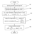
- some embodiments of the invention utilize the phases of the entries in the right singular matrix (V) to design W, as described below and as shown in the several steps of the flowchart illustrated in FIG. 5 .
- Step 501 Estimate the downlink channel matrix H.
- Step 502 Perform the SVD decomposition of the channel matrix H to obtain right singular matrix V.
- Step 504 Construct a matrix V L-phase of the same size as V L where (i,j) th element of V L-phase denotes the phase of the (i,j) th complex element in V L .
- Layer refers to number of independent data steams transmitted by the MIMO transmitter or by the transmitter in a communication system.
- Initialization Procedure An initialization procedure can be utilized for constructing the representative channel gain matrix to be used for the construction of the precode filter.
- the channel gain matrix H has N columns and M rows.
- the (i,j) th element of H represents the complex channel gain between the j th transmitter antenna and i th receiver antenna. These complex gains can be computed at the receiver by means of Pilots.
- the k th transmit antenna sends out a Pilot symbol which is pre-known at all receive antennas. This enables the receiver to compute the complex channel gain between the k th transmit antenna. This procedure is repeated for all transmit antennas in a sequential manner (i.e. 1 transmission per time slot).
- Channel Feedback to Transmitter There are several ways in which a transmitter can obtain the channel gain matrix for constructing the precode filter.
- the receiver sends the full channel matrix H to the transmitter using a feedback path. Subsequently, the receiver does some processing on the channel matrix H and sends the resultant matrix H eff to the transmitter using the feedback path. Then, the receiver does some processing on the channel matrix H and sends channel specific information in few bits utilizing codebooks.
- the transmitter can determine the channel gain matrix by using channel reciprocity.
- the two methods have varying complexity.
- the first method is based on SVD decomposition of the channel matrix H and gives the best performance.
- the second method does not require SVD decomposition and as a result experiences some performance loss.
- the steps (a)-(d) can be executed partially or fully at either the transmitter or the receiver.
- FIG. 6 illustrates a flowchart representing one possible implementation of the first method.
- Step 601 Receiver estimates downlink channel matrix H.
- Transmitter may also choose L column vectors of V that correspond to largest singular values of channel matrix H.
- Step 604 Transmitter constructs a matrix V L-phase of the same size as V L where (i,j) th element of V L-phase denotes the phase of the (i,j) th complex element in V L . That is, set (i,j) th entry of V L-phase as:
- Step 605 Transmitter constructs downlink precoder filter as
- the receiver may employ techniques other than SVD decomposition to compute right singular matrix V.
- FIG. 7 illustrates another possible implementation of the first method.
- Step 701 Receiver estimates downlink channel matrix H.
- Step 704 For L layer transmission, Receiver chooses L rows of H that correspond to largest row norms and constructs
- H _ _ L [ h _ _ 1 ... h _ _ L ] , where h k denotes the k th row vector of matrix H .
- h 1 has the largest row-norm, followed by h 2 and so on.
- Step 705 Receiver construct a matrix V L-phase whose (i,j) th element denotes the negative phase of the (j,i) th complex element in H L , that is
- Step 706 Receiver sends matrix V L-phase to the Transmitter either explicitly or via codebook method represented by few bits.
- Step 707 Transmitter constructs downlink precoder as
- FIG. 8 illustrates a second method which does not require SVD.
- Step 801 Estimate downlink channel matrix H.
- Step 802 For L layer transmission, chooses L rows of H with the largest row-norms. Let these rows be denoted by another matrix H L as
- H L [ h 1 ... h L ] , where h 1 has the largest row-norm followed by h 2 and so on.
- Step 803 Construct a matrix V L-phase whose (i,j) th element represents the negative phase of the (j,i) th complex element in H L defined as
- Step 804 Construct downlink precoder as
- Steps 801 - 804 can be executed in partial or full at the transmitter or the receiver.
- FIG. 9 illustrates one possible implementation of the second method.
- Step 901 Receiver estimates downlink channel matrix H.
- Step 902 For an L layer transmission, Receiver chooses L rows of H with the largest row-norms. Let these rows be denoted by another matrix H L as
- H L [ h 1 ... h L ] , where h 1 has the largest row-norm followed by h 2 and so on.
- Step 903 Receiver constructs a matrix V L-phase whose (i,j) th element represents the negative phase of the (j,i) th complex element in H L defined as
- Step 904 Receiver sends matrix V L-phase to the Transmitter either explicitly or via codebook method represented by few bits.
- Step 905 Transmitter constructs a downlink precoder as
- FIG. 10 illustrates another possible implementation of the second method.
- Step 1001 Receiver sends the full channel matrix H to the Transmitter via feedback channel.
- Step 1002 For L layer transmission, Transmitter chooses L rows of H with the largest row-norms. Let these rows be denoted by another matrix H L as
- H L [ h 1 ... h L ] , where h 1 has the largest row-norm followed by h 2 and so on.
- Step 1003 Transmitter constructs a matrix V L-phase whose (i,j) th element represents the negative phase of the (j,i) th complex element in H L defined as
- Step 1004 Transmitter constructs a downlink precoder as
- FIG. 11 illustrates an example implementation of a transmitter and a receiver in accordance with embodiments of the invention.
- the transmitter block and receiver block may have respective processing unites 1100 , 1101 which are implemented by hardware elements (e.g. one or more processors).
- Processing unit 1101 of the receiver block may be configured to construct information for transmitting to a transmitter for constructing precode filter W, based on implementations as described with respect to FIGS. 5-10 .
- the information to construct the precode filter is transmitted to the transmitter block through one or more antennas of the receiver block.
- processing unit 1100 of the transmitter block is configured to construct precode filter W represented by the equation
- the processing unit 1100 of the transmitter block is configured to apply the precode filter W to one or more antennas of the transmitter.
- these quantities take the form of electrical or magnetic signals or instructions capable of being stored, transferred, combined, compared, and otherwise manipulated. It has proven convenient at times, principally for reasons of common usage, to refer to these signals as bits, values, elements, symbols, characters, terms, numbers, instructions, or the like. It should be borne in mind, however, that all of these and similar terms are to be associated with the appropriate physical quantities and are merely convenient labels applied to these quantities.
- the present invention also relates to an apparatus for performing the operations herein.
- This apparatus may be specially constructed for the required purposes, or it may include one or more general-purpose computers selectively activated or reconfigured by one or more computer programs.
- Such computer programs may be stored in a computer-readable storage medium, such as, but not limited to optical disks, magnetic disks, read-only memories, random access memories, solid state devices and drives, or any other types of media suitable for storing electronic information.
- the algorithms and displays presented herein are not inherently related to any particular computer or other apparatus.
- the operations described above can be performed by hardware, software, or some combination of software and hardware.
- Various aspects of embodiments of the invention may be implemented using circuits and logic devices (hardware), while other aspects may be implemented using instructions stored on a machine-readable medium (software), which if executed by a processor, would cause the processor to perform a method to carry out embodiments of the invention.
- some embodiments of the invention may be performed solely in hardware, whereas other embodiments may be performed solely in software.
- the various functions described can be performed in a single unit, or can be spread across a number of components in any number of ways.
- the methods may be executed by a processor, such as a general purpose computer, based on instructions stored on a computer-readable medium. If desired, the instructions can be stored on the medium in a compressed and/or encrypted format.
Landscapes
- Engineering & Computer Science (AREA)
- Computer Networks & Wireless Communication (AREA)
- Signal Processing (AREA)
- Power Engineering (AREA)
- Radio Transmission System (AREA)
- Mobile Radio Communication Systems (AREA)
Abstract
Description
y k =w k X (4)
-
- a) Perform the SVD decomposition of the channel matrix: H=USVH (where U and V are left and right singular vector matrices, respectively; and S is a diagonal matrix)
- b) For L layer transmission, choose L column vectors of V that correspond to largest singular values of channel matrix H. Let this matrix be denoted by VL=[v1 v2 . . . vL], where vk denotes the kth column vector of matrix V.
- c) Construct an L×L diagonal matrix Λ such that (i,i)th element denotes the power allocated to the ith singular mode. Water-filling method can generate the optimal power allocation matrix Λ such that the sum of diagonal elements is less than or equal to the total transmit power PT.
- d) Precoder matrix is constructed as: W=VL*sqrt(Λ)
- E. Telatar, “Capacity of multi-antenna Gaussian channels,” Eur. Trans. Telecomm. ETT, vol. 10, no. 6, pp. 585-596, November 1999.
- M. Vu, “MISO capacity with Per-Antenna Power Constraint”, arXiv:1003.1738v1, Mar. 8, 2010.
- W. Yu and T. Lan, “Transmitter optimization for the multi-antenna downlink with per-antenna power constraints,” IEEE Transactions on Signal Processing, vol. 55, no. 6, pp. 2646-2660, 2007.
- S. Shi, M. Schubert, and H. Boche, “Per-antenna power constrained rate optimization for multiuser MIMO systems,” in International ITG Workshop on Smart Antennas (WSA), 2008, pp. 270-277.
- M. Codreanu, A. Tolli, M. Juntti, and M. Latva-aho, “MIMO Downlink Weighted Sum Rate Maximization with Power Constraints per Antenna Groups,” in IEEE VTC Spring, 2007, pp. 2048-2052.
In the equation, P represents power allocation; L represents a number of transmission layers; VL-phase represents a matrix where the (i,j)th element of VL-phase is equivalent to the phase of (i,j)th complex element in VL, wherein VL is based on a right singular matrix derived from channel matrix H. Channel matrix H is a matrix representing channel gain between at least one antenna at the transmitter and at least one antenna at a receiver.
-
- a) Perform the SVD decomposition of the channel matrix H as: H=USVH (where U and V are left and right singular vector matrices, respectively; and S is a diagonal matrix)
- b) For L layer transmission, choose L column vectors of V that correspond to largest singular values of channel matrix H. Let this matrix be denoted by VL=[v1 v2 . . . vL], where vk denotes the kth column vector of matrix V.
- c) Construct a matrix VL-phase of the same size as VL where (i,j)th element of VL-phase denotes the phase of the (i,j)th complex element in VL. That is set (i,j)th entry of VL-phase as:
where |.| denotes the absolute value of its argument.
-
- d) Construct precoder filter as
where P is the maximum power allowed at each transmit antenna. If the MIMO transmitter has a total available power PT, then P=PT/N.
where |.| denotes the absolute value of its argument.
where
where h1 has the largest row-norm followed by h2 and so on.
where h1 has the largest row-norm followed by h2 and so on.
where h1 has the largest row-norm followed by h2 and so on.
and as described with respect to
Claims (17)
Priority Applications (4)
| Application Number | Priority Date | Filing Date | Title |
|---|---|---|---|
| US13/069,093 US8917787B2 (en) | 2011-03-22 | 2011-03-22 | Systems and methods for creating a downlink precode for communication system with per-antenna power constraints |
| JP2012058159A JP5795978B2 (en) | 2011-03-22 | 2012-03-15 | System and method for creating downlink precoding for communication systems with per-antenna power constraints |
| EP12160612.3A EP2503706A3 (en) | 2011-03-22 | 2012-03-21 | Systems and methods for creating a downlink precode for communication system with per-antenna power constraints |
| CN201210077611.7A CN102694627B (en) | 2011-03-22 | 2012-03-22 | For the system and method to the communication system establishment downlink precoding had for the power constraint of each antenna |
Applications Claiming Priority (1)
| Application Number | Priority Date | Filing Date | Title |
|---|---|---|---|
| US13/069,093 US8917787B2 (en) | 2011-03-22 | 2011-03-22 | Systems and methods for creating a downlink precode for communication system with per-antenna power constraints |
Publications (2)
| Publication Number | Publication Date |
|---|---|
| US20120243631A1 US20120243631A1 (en) | 2012-09-27 |
| US8917787B2 true US8917787B2 (en) | 2014-12-23 |
Family
ID=45888029
Family Applications (1)
| Application Number | Title | Priority Date | Filing Date |
|---|---|---|---|
| US13/069,093 Expired - Fee Related US8917787B2 (en) | 2011-03-22 | 2011-03-22 | Systems and methods for creating a downlink precode for communication system with per-antenna power constraints |
Country Status (4)
| Country | Link |
|---|---|
| US (1) | US8917787B2 (en) |
| EP (1) | EP2503706A3 (en) |
| JP (1) | JP5795978B2 (en) |
| CN (1) | CN102694627B (en) |
Cited By (1)
| Publication number | Priority date | Publication date | Assignee | Title |
|---|---|---|---|---|
| US10447358B2 (en) | 2012-06-04 | 2019-10-15 | Trustees Of Tufts College | System, method and apparatus for multi-input multi-output communications over per-transmitter power-constrained channels |
Families Citing this family (5)
| Publication number | Priority date | Publication date | Assignee | Title |
|---|---|---|---|---|
| CN104349358B (en) * | 2013-08-05 | 2018-09-28 | 普天信息技术研究院有限公司 | A kind of antenna feeder optimization method |
| US9450657B2 (en) * | 2013-08-28 | 2016-09-20 | Nec Corporation | Low-complexity precoder design for large-scale MIMO communication systems |
| CN106716860B (en) * | 2014-09-03 | 2021-03-16 | 株式会社Ntt都科摩 | wireless transmitter |
| EP3258614B1 (en) * | 2015-03-03 | 2019-07-31 | Huawei Technologies Co. Ltd. | Data transmission method, apparatus and device |
| CN107733488B (en) * | 2017-10-16 | 2020-05-19 | 中南大学 | An improved method and system for water injection power distribution in a massive MIMO system |
Citations (7)
| Publication number | Priority date | Publication date | Assignee | Title |
|---|---|---|---|---|
| US6862271B2 (en) | 2002-02-26 | 2005-03-01 | Qualcomm Incorporated | Multiple-input, multiple-output (MIMO) systems with multiple transmission modes |
| US6940917B2 (en) | 2002-08-27 | 2005-09-06 | Qualcomm, Incorporated | Beam-steering and beam-forming for wideband MIMO/MISO systems |
| US20070249296A1 (en) | 2006-04-24 | 2007-10-25 | Howard Steven J | Reduced complexity beam-steered MIMO OFDM system |
| WO2009002078A2 (en) | 2007-06-26 | 2008-12-31 | Lg Electronics Inc. | Method of transmitting of data and configuring a codebook in multi antenna system |
| WO2010005988A2 (en) | 2008-07-07 | 2010-01-14 | Zte U.S.A., Inc. | Method and system for space-time power control for mimo transmissions |
| US20100150265A1 (en) * | 2005-09-30 | 2010-06-17 | Matsushita Electric Industrial Co., Ltd. | Antenna selection method and radio communication device |
| US20120140848A1 (en) * | 2010-12-03 | 2012-06-07 | Industrial Technology Research Institute | Transmitting Terminal and Transmit Antenna Selecting Method Thereof |
Family Cites Families (9)
| Publication number | Priority date | Publication date | Assignee | Title |
|---|---|---|---|---|
| US6785520B2 (en) * | 2002-03-01 | 2004-08-31 | Cognio, Inc. | System and method for antenna diversity using equal power joint maximal ratio combining |
| US7099678B2 (en) * | 2003-04-10 | 2006-08-29 | Ipr Licensing, Inc. | System and method for transmit weight computation for vector beamforming radio communication |
| JP2005252834A (en) * | 2004-03-05 | 2005-09-15 | Rikogaku Shinkokai | MIMO eigenmode adaptive transmission system and MIMO-OFDM eigenmode adaptive transmission system |
| GB0519749D0 (en) * | 2005-07-08 | 2005-11-09 | Koninkl Philips Electronics Nv | Transmission over a multiple input multiple output broadcast channel (MIMO-BC) |
| ES2688275T3 (en) * | 2005-08-22 | 2018-10-31 | Qualcomm Incorporated | Procedure and apparatus for the selection of virtual antennas |
| TWI433484B (en) * | 2006-02-22 | 2014-04-01 | Koninkl Philips Electronics Nv | System, apparatus, and method for asymmetrical beamforming with equal-power transmissions |
| ATE539499T1 (en) * | 2007-02-14 | 2012-01-15 | Lg Electronics Inc | DATA SENDING AND RECEIVING METHOD WITH PHASE SHIFT BASED PRECODING AND TRANSMITTER/RECEIVER SUPPORTING THIS |
| ATE511250T1 (en) * | 2007-12-03 | 2011-06-15 | Ericsson Telefon Ab L M | METHOD AND DEVICE FOR SPATIAL PRECODING |
| JP5340634B2 (en) * | 2008-05-12 | 2013-11-13 | 株式会社エヌ・ティ・ティ・ドコモ | Wireless communication apparatus and wireless communication method |
-
2011
- 2011-03-22 US US13/069,093 patent/US8917787B2/en not_active Expired - Fee Related
-
2012
- 2012-03-15 JP JP2012058159A patent/JP5795978B2/en not_active Expired - Fee Related
- 2012-03-21 EP EP12160612.3A patent/EP2503706A3/en not_active Withdrawn
- 2012-03-22 CN CN201210077611.7A patent/CN102694627B/en not_active Expired - Fee Related
Patent Citations (10)
| Publication number | Priority date | Publication date | Assignee | Title |
|---|---|---|---|---|
| US6862271B2 (en) | 2002-02-26 | 2005-03-01 | Qualcomm Incorporated | Multiple-input, multiple-output (MIMO) systems with multiple transmission modes |
| US6940917B2 (en) | 2002-08-27 | 2005-09-06 | Qualcomm, Incorporated | Beam-steering and beam-forming for wideband MIMO/MISO systems |
| US7194040B2 (en) | 2002-08-27 | 2007-03-20 | Qualcomm Incorporated | Beam-steering and beam-forming for wideband MIMO/MISO systems |
| US20100150265A1 (en) * | 2005-09-30 | 2010-06-17 | Matsushita Electric Industrial Co., Ltd. | Antenna selection method and radio communication device |
| US20070249296A1 (en) | 2006-04-24 | 2007-10-25 | Howard Steven J | Reduced complexity beam-steered MIMO OFDM system |
| WO2007127744A1 (en) | 2006-04-24 | 2007-11-08 | Qualcomm Incorporated | Reduced complexity beam-steered mimo ofdm system |
| CN101427485A (en) | 2006-04-24 | 2009-05-06 | 高通股份有限公司 | Reduced complexity beam steered MIMO OFDM system |
| WO2009002078A2 (en) | 2007-06-26 | 2008-12-31 | Lg Electronics Inc. | Method of transmitting of data and configuring a codebook in multi antenna system |
| WO2010005988A2 (en) | 2008-07-07 | 2010-01-14 | Zte U.S.A., Inc. | Method and system for space-time power control for mimo transmissions |
| US20120140848A1 (en) * | 2010-12-03 | 2012-06-07 | Industrial Technology Research Institute | Transmitting Terminal and Transmit Antenna Selecting Method Thereof |
Non-Patent Citations (6)
| Title |
|---|
| Chinese office action mailed on May 29, 2014, Chinese Application No. 201210077611.7. |
| I. Emre Telatar, "Capacity of Multi-antenna Gaussian Channels", Eur. Trans. Telecomm. ETT, Nov. 1999, 28 pages, vol. 10, No. 6. |
| M. Codreanu, et al., "MIMO Downlink Weighted Sum Rate Maximization with Power Constraints per Antenna Groups", IEEE VTC Spring, 2007, pp. 2048-2052. |
| Mai Vu, "MISO Capacity with Per-Antenna Power Constraint", Mar. 8, 2010, 15 pages, arXiv:1003.1738v1, Department of Electrical and Computer Engineering, McGill University, Montreal, H3A2A7. |
| Shuying Shi, et al., "Per-Antenna Power Constrained Rate Optimization for Multiuser MIMO Systems", International ITG Workshop on Smart Antennas (WSA), 2008, pp. 270-277. |
| Wei Yu, et al., "Transmitter Optimization for the Multi-Antenna Downlink With Per-Antenna Power Constraints", IEEE Transactions on Signal Processing, Jun. 2007, pp. 2646-2660, vol. 55, No. 6. |
Cited By (1)
| Publication number | Priority date | Publication date | Assignee | Title |
|---|---|---|---|---|
| US10447358B2 (en) | 2012-06-04 | 2019-10-15 | Trustees Of Tufts College | System, method and apparatus for multi-input multi-output communications over per-transmitter power-constrained channels |
Also Published As
| Publication number | Publication date |
|---|---|
| CN102694627B (en) | 2015-10-28 |
| EP2503706A2 (en) | 2012-09-26 |
| JP2012199920A (en) | 2012-10-18 |
| EP2503706A3 (en) | 2016-03-02 |
| CN102694627A (en) | 2012-09-26 |
| US20120243631A1 (en) | 2012-09-27 |
| EP2503706A9 (en) | 2012-10-31 |
| JP5795978B2 (en) | 2015-10-14 |
Similar Documents
| Publication | Publication Date | Title |
|---|---|---|
| EP2229740B1 (en) | Zero-forcing linear beamforming for coordinated cellular networks with distributed antennas | |
| Kang et al. | Capacity of MIMO Rician channels | |
| US8917787B2 (en) | Systems and methods for creating a downlink precode for communication system with per-antenna power constraints | |
| CN101631004B (en) | Pre-coding method and pre-coding system and construction method of pre-coding code book | |
| EP3528394B1 (en) | Communication method, terminal and base station | |
| US8391393B2 (en) | Uplink precoding method in 4-Tx system | |
| CN110622434A (en) | Receiver, communication system and computer-implemented method for supporting both analog and digital beamforming in a communication system | |
| US10757658B2 (en) | Power allocation and precoding matrix computation method in a wireless communication system | |
| US8488708B2 (en) | Rotating reference codebook that is used in a multiple-input multiple-output (MIMO) communication system | |
| Lee et al. | MIMO transceiver designs for spatial sensing in cognitive radio networks | |
| US9673878B1 (en) | Systems and methods for performing precoding in multi-user systems | |
| Wang et al. | Performance loss of hybrid beamforming with imperfect phase shifters in millimeter wave systems | |
| CN101515906B (en) | Precoding method for mapping between data flow and wave packet | |
| CN111130606B (en) | Pre-coding method and device based on power distribution | |
| KR101691295B1 (en) | Multi-antenna transmission beam design device and method, and transmission terminal thereof | |
| Chen et al. | Large Language Model-Empowered Channel Prediction and Predictive Beamforming for LEO Satellite Communications | |
| Shi et al. | Maximum product of effective channel gains: an innovative user selection algorithm for downlink multi‐user multiple input and multiple output | |
| US11973562B2 (en) | Internal data transfer in a multiple-antenna communication system | |
| Bose et al. | Multiuser mimo capacity with limited feedback trellis exploration based precoder | |
| Medra et al. | Total power minimization: Joint antenna selection and beamforming design | |
| Mejri et al. | Hybrid precoding based on iterative weighted thresholding approach in MmWave MIMO transmitters using sub-connected strategy | |
| Schmidt et al. | Algorithms for improper single-stream MIMO interference networks | |
| Ko et al. | Determinant based multiuser mimo scheduling with reduced pilot overhead | |
| Li et al. | On ergodic secrecy capacity for Gaussian MISO wiretap channels | |
| MITRA | Capacity bounds for amplitude-constrained MIMO channels |
Legal Events
| Date | Code | Title | Description |
|---|---|---|---|
| AS | Assignment |
Owner name: HITACHI, LTD., JAPAN Free format text: ASSIGNMENT OF ASSIGNORS INTEREST;ASSIGNOR:GAUR, SUDHANSHU;REEL/FRAME:026006/0487 Effective date: 20110323 |
|
| FEPP | Fee payment procedure |
Free format text: PAYOR NUMBER ASSIGNED (ORIGINAL EVENT CODE: ASPN); ENTITY STATUS OF PATENT OWNER: LARGE ENTITY |
|
| FEPP | Fee payment procedure |
Free format text: MAINTENANCE FEE REMINDER MAILED (ORIGINAL EVENT CODE: REM.) |
|
| LAPS | Lapse for failure to pay maintenance fees |
Free format text: PATENT EXPIRED FOR FAILURE TO PAY MAINTENANCE FEES (ORIGINAL EVENT CODE: EXP.); ENTITY STATUS OF PATENT OWNER: LARGE ENTITY |
|
| STCH | Information on status: patent discontinuation |
Free format text: PATENT EXPIRED DUE TO NONPAYMENT OF MAINTENANCE FEES UNDER 37 CFR 1.362 |
|
| FP | Lapsed due to failure to pay maintenance fee |
Effective date: 20181223 |