US891769A - Kitchen-range. - Google Patents
Kitchen-range. Download PDFInfo
- Publication number
- US891769A US891769A US8293701A US1901082937A US891769A US 891769 A US891769 A US 891769A US 8293701 A US8293701 A US 8293701A US 1901082937 A US1901082937 A US 1901082937A US 891769 A US891769 A US 891769A
- Authority
- US
- United States
- Prior art keywords
- water
- chamber
- chambers
- oven
- range
- Prior art date
- Legal status (The legal status is an assumption and is not a legal conclusion. Google has not performed a legal analysis and makes no representation as to the accuracy of the status listed.)
- Expired - Lifetime
Links
Images

Classifications
-
- F—MECHANICAL ENGINEERING; LIGHTING; HEATING; WEAPONS; BLASTING
- F24—HEATING; RANGES; VENTILATING
- F24C—DOMESTIC STOVES OR RANGES ; DETAILS OF DOMESTIC STOVES OR RANGES, OF GENERAL APPLICATION
- F24C13/00—Stoves or ranges with additional provisions for heating water
Definitions
- I, AUGUST FRONDEL residing at Omaha, in the county of Douglas and State of Kansas, have invented certain useful Im rovements in Kitchen-Ranges; and I 'do f1 is a full, clear, and exact descri tion thereof, such as will enable others skilFed in the art to which it appertains to make and use the same, reference being had to the aocom panying drawings, which form a part of this specification.
- This invention relates to a combined cooking and heating system.
- One object of the invention is to provid a system of the nature stated embodying such characteristics that a kitchen range may have its structural details arranged in an organization capable for kitchen or cooking purposes or for the heating of a building or both.
- Another object of the invention resides in provision of a heating or cooking apparatus constructed and arranged whereby the water containing jackets are wholly inclosed within the outer walls of the structure to facilitate the heating of the Water, confining the heat within the walls with an economical handling of fuel in direct contra-distinction to structures wherein the water tanks are partially ex osed and form part of the outside wall.
- Figure 1 is a perspective viewof a kitchen range embodying my invention.
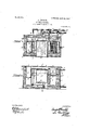
- Fig. 2 is a transverse sectional view.
- Fig. 3 is a horizontal sectional view.
- the walls thereof be composed of masonry or other suitable material, with the outer faces of the walls shielded by metallic sheathing, if desired.
- These outer walls of masonry or vi her suitable material provide a casing A in is a vertical longitudinal sectional ereby declare that the following which the characteristic features of my invention are inclosed, there being a transversely disposed bridge wall T arranged adj acent one end of the range to cooperate with said end, and the front and rear of the latter, to form a narrow chamber.
- a suitable grate 5 Journaled in any suitable manner in the top of the bridge wall T and the aforesaid adjacent end wall of the range, is a suitable grate 5, the trunnion 6 of which is extended entirely through said adjacent end wall to provide means whereby the grate may be operated, the grate dividing the aforesa'd chamber to provide the fire box B and the ashpit C with which latter communication may be had through the opening 3 provided with the damper 4.
- the upper and lower water chambers 16 and 18 communicating at 16, the upper chamber 16 terminating short a suitable distance below the top of the range.
- Disposed directly opposite this pair of superimposed communicating chambers 16 and 18 is another pair of superimposed water chambers 7 and 8 communicating at 7
- These pairs of oppositely disposed water chambers compose the sides of the fire pot B of the range, all of the chambers being positioned immediately above the grate 5, as clearly shown in Fig. 4, it being obvious that the opening 3 leading to the ash pit 0 provides the usual draft flue near the base of the structure.
- the character 34 designates a longitudinally extending wall preferably spaced from the rear wall of masonry to provide a flue l/V and to also rovide abase for the support of the rear Wal supported within an opening formed in the front wall of the structure, there being a door 31 closing the front of the oven.
- a water chamber M Disposed beneath the oven D is a water chamber M, there being a flue F between the oven and chamber M, which has communication with the aforesaid flue W by way of the opening G formed by thewall 34 terminates short of the aforesaid bridge Wall T.
- the compartments K are made in sections to provide additional heating surface between them, the spaces between which are V-shaped, as shown in Fig. 3. Further, the
- the character N represents a water chamber supported in any suitable manner in the upper part ter, opposite the end in which the fire pot is disposed.
- This water chamber N is designed to be used for soft Water for washing purposes and the water may be inserted or removed through one of the lids a, there being lids formed in the top of the range as is customary in a stove of this character. Beneath the water chamberNis awarming oven S to which access may be had by way of the door 38.
- this invention contemplates the heating of a building, and it is for this reason that the numerous water tanks hereinbefore referred to are incorporated within the walls of the range, it being preferred to heat the room by means of a hot.
- a circulating coil L which has communication at one end with one compartment of the sectionized chamber K, as indicated at- 24' in Fig. 3, with its opposite end communicating with the upper chamber 16 disposed upon the top of the bridge wall T.
- the various divisions of flow of the water are reunited in the pipe 17 and pass again to the radiators.
- Thecoil L and the upper tanks 16 and 7 contain the hottest water and as they are in direct communication with the hot Water supply pipe 17, a supply of hot water is always at ones command.
- a casing In a range, a casing, an oven disposed within the casmg, the oven terminating short of the rear, top and bottom of the casing, pairs of superimposed water. chambers forming opposite sides of the fire pot of the range, said pairs of chambers havmg communication withone another, other chambers confined within the casin a coil having communication with one 0 said other chambers communicating 'with the coils and the c ambers to supply a heating medium to remote sources.
- a casing an oven disposed within the casing, water chambers including a sectionized chamber, and a soft water compartment independent of said chamber, the sectionized chamber being arranged adjacent said compartment and exposing the latter at its side adjacent the sectionized chamber to the products of combustion, all of said chambers having communication with one another.
- water chambers including a sectionized chamber, a soft water com-- partment independent of said chamber, the
- sectionized chamber being arranged adj acent
- said compartment and exposing the latter at its side adjacent the sectionized chamber products of combustion, 'all of said chambers having communication with one another, and a hot Water supply system including a coil having communication with said chambers.
Landscapes
- Engineering & Computer Science (AREA)
- Chemical & Material Sciences (AREA)
- Combustion & Propulsion (AREA)
- Mechanical Engineering (AREA)
- General Engineering & Computer Science (AREA)
- Cookers (AREA)
Description
PATENTED JUNE 23, 1908} A. FRONDEL. KITGHENRANGB. APPLICATION FILED 11017.19. 1901.
2 SHEETS-SHEET 1 PATENTED JUNE 23, 190.8.
A. FRONDEL. KITCHEN RANGE. APPLIOATION rILnn Nov. 19. 1901.
2 SHEETS-SHEET 2.
\ {NVENTOR ATTORNEY W/ TNEJSES AUGUST FRDNDEL, OF OMAHA, NEBRASKA.
v KITCHEN-RANGE.
Specification of Letters Patent.
Patented June 23, 1908.
. Application filed November 19,1901. Serial No. 82,937.
To all whom it may concern:
Be it known that I, AUGUST FRONDEL, residing at Omaha, in the county of Douglas and State of Nebraska, have invented certain useful Im rovements in Kitchen-Ranges; and I 'do f1 is a full, clear, and exact descri tion thereof, such as will enable others skilFed in the art to which it appertains to make and use the same, reference being had to the aocom panying drawings, which form a part of this specification.
This invention relates to a combined cooking and heating system.
One object of the invention is to provid a system of the nature stated embodying such characteristics that a kitchen range may have its structural details arranged in an organization capable for kitchen or cooking purposes or for the heating of a building or both.
Another object of the invention resides in provision of a heating or cooking apparatus constructed and arranged whereby the water containing jackets are wholly inclosed within the outer walls of the structure to facilitate the heating of the Water, confining the heat within the walls with an economical handling of fuel in direct contra-distinction to structures wherein the water tanks are partially ex osed and form part of the outside wall.
the present invention ith the above and other objects in view,
consists in the combination and arrangement of parts hereinafter more fully described, illustrated in the accompanying drawings, and particularly pointed out in the appended claims, it being understood that changes may be made in the form, proportion, size and minor details,
' without departing from the s irit or sacri ficing any of the advantages t ereof. I
the drawings :Figure 1 is a perspective viewof a kitchen range embodying my invention. Fig. 2 is a transverse sectional view. Fig. 3 is a horizontal sectional view.
Fig. 4 View.
Referring now more particularly to the accompanying drawings, it will be seen that in my peculiar form of range I prefer that the walls thereof be composed of masonry or other suitable material, with the outer faces of the walls shielded by metallic sheathing, if desired. These outer walls of masonry or vi her suitable material provide a casing A in is a vertical longitudinal sectional ereby declare that the following which the characteristic features of my invention are inclosed, there being a transversely disposed bridge wall T arranged adj acent one end of the range to cooperate with said end, and the front and rear of the latter, to form a narrow chamber. Journaled in any suitable manner in the top of the bridge wall T and the aforesaid adjacent end wall of the range, is a suitable grate 5, the trunnion 6 of which is extended entirely through said adjacent end wall to provide means whereby the grate may be operated, the grate dividing the aforesa'd chamber to provide the fire box B and the ashpit C with which latter communication may be had through the opening 3 provided with the damper 4.
Disposed upon the bridge wall T are the upper and lower water chambers 16 and 18 communicating at 16, the upper chamber 16 terminating short a suitable distance below the top of the range. Disposed directly opposite this pair of superimposed communicating chambers 16 and 18 is another pair of superimposed water chambers 7 and 8 communicating at 7 These pairs of oppositely disposed water chambers compose the sides of the fire pot B of the range, all of the chambers being positioned immediately above the grate 5, as clearly shown in Fig. 4, it being obvious that the opening 3 leading to the ash pit 0 provides the usual draft flue near the base of the structure.
The character 34 designates a longitudinally extending wall preferably spaced from the rear wall of masonry to provide a flue l/V and to also rovide abase for the support of the rear Wal supported within an opening formed in the front wall of the structure, there being a door 31 closing the front of the oven.
' Disposed beneath the oven D is a water chamber M, there being a flue F between the oven and chamber M, which has communication with the aforesaid flue W by way of the opening G formed by thewall 34 terminates short of the aforesaid bridge Wall T.
Reference to Fig. 4 of the drawings Will disclose that the oven D is disposed against the bridge wall T and the up er and lower water chambers 16 and 18, and upon the opposite side of the oven and in spaced relation thereto I provide a sectional water chamber composed of a series of substantially elongated vertically disposed compartment Ii,
of the oven D, whose front is reason of the fact that all of which have communication with the water chamber M through the pipe connections 25.
The compartments K are made in sections to provide additional heating surface between them, the spaces between which are V-shaped, as shown in Fig. 3. Further, the
' sections K permit a portion of the combustion products to reach the side of the soft water chamber N and heat the water The character N represents a water chamber supported in any suitable manner in the upper part ter, opposite the end in which the fire pot is disposed. This water chamber N is designed to be used for soft Water for washing purposes and the water may be inserted or removed through one of the lids a, there being lids formed in the top of the range as is customary in a stove of this character. Beneath the water chamberNis awarming oven S to which access may be had by way of the door 38.
From the fore oing it will be seen that the products of GOII1%l1St1OIl generated in the fire pot B escape over the upper water chamber 16, thence over the to of the oven D, into the flue F by we. of the flue E throu h the communication (it to the outer flue from which latter they escape through the chimney by way of the opening :10. Thus the hot water tanks andthe oven are efliciently heated by the circulation of the products of combustion in the manner thus related without the loss of heat and with a comparatively small consum tion of fuel.
As premise in the foregoing this invention contemplates the heating of a building, and it is for this reason that the numerous water tanks hereinbefore referred to are incorporated within the walls of the range, it being preferred to heat the room by means of a hot.
water circulating system. To this end I dispose immediately upon the top of the oven D a circulating coil L which has communication at one end with one compartment of the sectionized chamber K, as indicated at- 24' in Fig. 3, with its opposite end communicating with the upper chamber 16 disposed upon the top of the bridge wall T.
27 indicates the feed water pipe which communicates with the chamber M and thence through the pipes 25 with one of the tank sections K, as indicated at 26 in Fig. 4. As the water floods the lower cham-' ber M it rises through the pipes 25 to flood the divided'or sectionized c amber K, filling of the latter.
all compartments The overflow from the chamber K passes through.
the coil L into the chamber 16 and also through a pipe 15 which communicates with the last chamber K, shown in Fig. 2, which by means of pipe 27 is continued to the pi e 12, which enters the lower chamber 8 part y skirting three sides of the fire box, as shown in Fig. 4. Extending. from the p1pe 27 is a therein.
of the range at the end of the latpipe 13 which enters the lower chamber 18 so that as the water rises within the sectionized chamber 7 it finds an escape through the pipe 27 to flood the chambers 8 and 18.
Extending from the coil L, as shown in dotted lines in Fi 3, is a pipe 21, which communicates wit the hot Water supply pi e 17 which latter is connected to a suitab le pipe U shown in Fig. 1, provided with a steam gage V and a water gage W. Extending from the upper hot Water tank 16, as shown in Fig. 3, is a pipe 20 also led into the hot water su ply pipe 17, while extending from the tan 7 is a pipe 9 leading into the hot water supply pipe 17 The various divisions of flow of the water are reunited in the pipe 17 and pass again to the radiators.
Thecoil L and the upper tanks 16 and 7 contain the hottest water and as they are in direct communication with the hot Water supply pipe 17, a supply of hot water is always at ones command.
The door 37 shownin Fig. 1 removal of soot from the smoke chamber F.
I claim:
1. In a range, a casing, an oven within the casing and terminating short of the to bottom and rear of the casin vertica communicating hot water cham ers arranged at one side of said oven and spaced therefrom,
a horizontal hot water chamber beneath said oven and spaced therefrom and communicating withsaid vertical chambers, the spaces between said oven and chambers provlding a flue communicating with the .casmg above and below andat the rear of the oven, other communicating hot water chambers at the opposite side of the oven, communicating means between the last mentioned chambers and the vertical chambers, a pipe coil arranged upon top of the oven and having communicatlon with the last mentioned chambers and the vertical chambers, and plilpes having communication with said pipe 00' to supplya heating medium to remote sources.
' 2. In a range, a casing, an oven disposed within the casmg, the oven terminating short of the rear, top and bottom of the casing, pairs of superimposed water. chambers forming opposite sides of the fire pot of the range, said pairs of chambers havmg communication withone another, other chambers confined within the casin a coil having communication with one 0 said other chambers communicating 'with the coils and the c ambers to supply a heating medium to remote sources.
3. In a range,'a casing, an oven disposed within the casing, pairs of superimposed water chambers forming the sides of the. fire pot, other chambers arranged within the casing having communication with one another and with the aforesaid fire pot chaml bers, a pipe coil arranged upon top of the and with the pairs of chambers, and ipes facilitates the oven and having communication with the chambers, and pipes communicating with said coil and the chambers to supply a heating medium to remote sources, said elements being constructed and arranged to cause the products of combustion to pass over the coil and oven downwardly along one side of the latter and out of the casing by way of the bottom of the oven and the rear thereof.
4. In a range, a casing, an oven disposed within the casing, water chambers including a sectionized chamber, and a soft water compartment independent of said chamber, the sectionized chamber being arranged adjacent said compartment and exposing the latter at its side adjacent the sectionized chamber to the products of combustion, all of said chambers having communication with one another.
to the 5. In a range, a casing,
water chambers including a sectionized chamber, a soft water com-- partment independent of said chamber, the
sectionized chamber being arranged adj acent,
said compartment and exposing the latter at its side adjacent the sectionized chamber products of combustion, 'all of said chambers having communication with one another, and a hot Water supply system including a coil having communication with said chambers.
In testimony whereof I have signed my name in the presence of two witnesses.
AUGUST FRONDEL.
Witnesses:
KATIE FRONDEL, GEORGE W. SUES.
Priority Applications (1)
| Application Number | Priority Date | Filing Date | Title |
|---|---|---|---|
| US8293701A US891769A (en) | 1901-11-19 | 1901-11-19 | Kitchen-range. |
Applications Claiming Priority (1)
| Application Number | Priority Date | Filing Date | Title |
|---|---|---|---|
| US8293701A US891769A (en) | 1901-11-19 | 1901-11-19 | Kitchen-range. |
Publications (1)
| Publication Number | Publication Date |
|---|---|
| US891769A true US891769A (en) | 1908-06-23 |
Family
ID=2960200
Family Applications (1)
| Application Number | Title | Priority Date | Filing Date |
|---|---|---|---|
| US8293701A Expired - Lifetime US891769A (en) | 1901-11-19 | 1901-11-19 | Kitchen-range. |
Country Status (1)
| Country | Link |
|---|---|
| US (1) | US891769A (en) |
-
1901
- 1901-11-19 US US8293701A patent/US891769A/en not_active Expired - Lifetime
Similar Documents
| Publication | Publication Date | Title |
|---|---|---|
| US891769A (en) | Kitchen-range. | |
| US2391028A (en) | Hot air heating furnace | |
| US1280235A (en) | Stove. | |
| US2038123A (en) | Boiler | |
| US2295889A (en) | Cooking range or stove | |
| US1931959A (en) | Stove or furnace construction | |
| US1382014A (en) | Heating-stove | |
| US914085A (en) | Range. | |
| US583705A (en) | Camp stove | |
| US559918A (en) | Heating and ventilating furnace | |
| US1576603A (en) | Heating stove | |
| US2789520A (en) | Furnace combustion chamber | |
| US1828319A (en) | Hot air heater | |
| US1856693A (en) | Hot water stove and storage tank | |
| US1517738A (en) | Heater | |
| US1417404A (en) | Oveit | |
| US1527732A (en) | Hot-air circulator for heating stoves | |
| US9204A (en) | Hot-air furnace | |
| US1422472A (en) | Cooker and boiler | |
| US507017A (en) | Stove or furnace | |
| US1245309A (en) | Stove. | |
| US708373A (en) | Combined hot-air and water or steam heater. | |
| US1459648A (en) | Steam boiler | |
| US1131573A (en) | Stove and range. | |
| US1505627A (en) | Fireplace for domestic heating |