US8916443B2 - Semiconductor device with epitaxial source/drain facetting provided at the gate edge - Google Patents
Semiconductor device with epitaxial source/drain facetting provided at the gate edge Download PDFInfo
- Publication number
- US8916443B2 US8916443B2 US13/534,407 US201213534407A US8916443B2 US 8916443 B2 US8916443 B2 US 8916443B2 US 201213534407 A US201213534407 A US 201213534407A US 8916443 B2 US8916443 B2 US 8916443B2
- Authority
- US
- United States
- Prior art keywords
- region
- raised region
- trench
- spacers
- drain
- Prior art date
- Legal status (The legal status is an assumption and is not a legal conclusion. Google has not performed a legal analysis and makes no representation as to the accuracy of the status listed.)
- Expired - Fee Related, expires
Links
- 239000004065 semiconductor Substances 0.000 title claims abstract description 29
- 125000006850 spacer group Chemical group 0.000 claims abstract description 48
- 238000000034 method Methods 0.000 claims abstract description 35
- 230000015572 biosynthetic process Effects 0.000 claims description 24
- 229910021332 silicide Inorganic materials 0.000 claims description 23
- FVBUAEGBCNSCDD-UHFFFAOYSA-N silicide(4-) Chemical compound [Si-4] FVBUAEGBCNSCDD-UHFFFAOYSA-N 0.000 claims description 23
- 230000008569 process Effects 0.000 claims description 18
- 239000012212 insulator Substances 0.000 claims description 9
- 238000005530 etching Methods 0.000 claims description 7
- 239000000758 substrate Substances 0.000 claims description 6
- 230000003071 parasitic effect Effects 0.000 claims description 5
- 239000013078 crystal Substances 0.000 claims description 4
- 238000013461 design Methods 0.000 description 63
- 238000002955 isolation Methods 0.000 description 16
- 239000000463 material Substances 0.000 description 15
- 238000012938 design process Methods 0.000 description 14
- 239000003989 dielectric material Substances 0.000 description 10
- 238000004519 manufacturing process Methods 0.000 description 8
- 238000004088 simulation Methods 0.000 description 8
- 238000012360 testing method Methods 0.000 description 8
- VYPSYNLAJGMNEJ-UHFFFAOYSA-N Silicium dioxide Chemical compound O=[Si]=O VYPSYNLAJGMNEJ-UHFFFAOYSA-N 0.000 description 6
- 230000000694 effects Effects 0.000 description 6
- 229910052581 Si3N4 Inorganic materials 0.000 description 5
- XUIMIQQOPSSXEZ-UHFFFAOYSA-N Silicon Chemical compound [Si] XUIMIQQOPSSXEZ-UHFFFAOYSA-N 0.000 description 5
- 229910000577 Silicon-germanium Inorganic materials 0.000 description 5
- 229910052799 carbon Inorganic materials 0.000 description 5
- 229910052751 metal Inorganic materials 0.000 description 5
- 239000002184 metal Substances 0.000 description 5
- 238000012545 processing Methods 0.000 description 5
- 229910052710 silicon Inorganic materials 0.000 description 5
- 239000010703 silicon Substances 0.000 description 5
- HQVNEWCFYHHQES-UHFFFAOYSA-N silicon nitride Chemical compound N12[Si]34N5[Si]62N3[Si]51N64 HQVNEWCFYHHQES-UHFFFAOYSA-N 0.000 description 5
- 229910052814 silicon oxide Inorganic materials 0.000 description 5
- 238000003860 storage Methods 0.000 description 5
- PXHVJJICTQNCMI-UHFFFAOYSA-N Nickel Chemical compound [Ni] PXHVJJICTQNCMI-UHFFFAOYSA-N 0.000 description 4
- 238000005229 chemical vapour deposition Methods 0.000 description 4
- 238000000151 deposition Methods 0.000 description 4
- 239000002019 doping agent Substances 0.000 description 4
- 238000000059 patterning Methods 0.000 description 4
- 230000009467 reduction Effects 0.000 description 4
- OKTJSMMVPCPJKN-UHFFFAOYSA-N Carbon Chemical compound [C] OKTJSMMVPCPJKN-UHFFFAOYSA-N 0.000 description 3
- 230000005540 biological transmission Effects 0.000 description 3
- 230000008021 deposition Effects 0.000 description 3
- 238000005516 engineering process Methods 0.000 description 3
- MRELNEQAGSRDBK-UHFFFAOYSA-N lanthanum(3+);oxygen(2-) Chemical compound [O-2].[O-2].[O-2].[La+3].[La+3] MRELNEQAGSRDBK-UHFFFAOYSA-N 0.000 description 3
- TWNQGVIAIRXVLR-UHFFFAOYSA-N oxo(oxoalumanyloxy)alumane Chemical compound O=[Al]O[Al]=O TWNQGVIAIRXVLR-UHFFFAOYSA-N 0.000 description 3
- RVTZCBVAJQQJTK-UHFFFAOYSA-N oxygen(2-);zirconium(4+) Chemical compound [O-2].[O-2].[Zr+4] RVTZCBVAJQQJTK-UHFFFAOYSA-N 0.000 description 3
- 229910001928 zirconium oxide Inorganic materials 0.000 description 3
- ZOXJGFHDIHLPTG-UHFFFAOYSA-N Boron Chemical compound [B] ZOXJGFHDIHLPTG-UHFFFAOYSA-N 0.000 description 2
- GWEVSGVZZGPLCZ-UHFFFAOYSA-N Titan oxide Chemical compound O=[Ti]=O GWEVSGVZZGPLCZ-UHFFFAOYSA-N 0.000 description 2
- 238000004458 analytical method Methods 0.000 description 2
- 229910052785 arsenic Inorganic materials 0.000 description 2
- RQNWIZPPADIBDY-UHFFFAOYSA-N arsenic atom Chemical compound [As] RQNWIZPPADIBDY-UHFFFAOYSA-N 0.000 description 2
- 229910052796 boron Inorganic materials 0.000 description 2
- 238000013500 data storage Methods 0.000 description 2
- 238000010586 diagram Methods 0.000 description 2
- 229910052732 germanium Inorganic materials 0.000 description 2
- GNPVGFCGXDBREM-UHFFFAOYSA-N germanium atom Chemical compound [Ge] GNPVGFCGXDBREM-UHFFFAOYSA-N 0.000 description 2
- BHEPBYXIRTUNPN-UHFFFAOYSA-N hydridophosphorus(.) (triplet) Chemical compound [PH] BHEPBYXIRTUNPN-UHFFFAOYSA-N 0.000 description 2
- 238000011065 in-situ storage Methods 0.000 description 2
- 150000002739 metals Chemical class 0.000 description 2
- 229910052759 nickel Inorganic materials 0.000 description 2
- 229910021334 nickel silicide Inorganic materials 0.000 description 2
- RUFLMLWJRZAWLJ-UHFFFAOYSA-N nickel silicide Chemical compound [Ni]=[Si]=[Ni] RUFLMLWJRZAWLJ-UHFFFAOYSA-N 0.000 description 2
- 238000001020 plasma etching Methods 0.000 description 2
- 229910021420 polycrystalline silicon Inorganic materials 0.000 description 2
- 238000012795 verification Methods 0.000 description 2
- -1 HfOxNy Inorganic materials 0.000 description 1
- 229910002244 LaAlO3 Inorganic materials 0.000 description 1
- 229910004541 SiN Inorganic materials 0.000 description 1
- 229910002370 SrTiO3 Inorganic materials 0.000 description 1
- 229910004491 TaAlN Inorganic materials 0.000 description 1
- 229910010303 TiOxNy Inorganic materials 0.000 description 1
- ATJFFYVFTNAWJD-UHFFFAOYSA-N Tin Chemical compound [Sn] ATJFFYVFTNAWJD-UHFFFAOYSA-N 0.000 description 1
- 229910003134 ZrOx Inorganic materials 0.000 description 1
- LEVVHYCKPQWKOP-UHFFFAOYSA-N [Si].[Ge] Chemical compound [Si].[Ge] LEVVHYCKPQWKOP-UHFFFAOYSA-N 0.000 description 1
- 230000002411 adverse Effects 0.000 description 1
- 229910052782 aluminium Inorganic materials 0.000 description 1
- 238000005266 casting Methods 0.000 description 1
- 238000012512 characterization method Methods 0.000 description 1
- 229910052681 coesite Inorganic materials 0.000 description 1
- 238000011960 computer-aided design Methods 0.000 description 1
- 239000004020 conductor Substances 0.000 description 1
- 229910052906 cristobalite Inorganic materials 0.000 description 1
- 238000000407 epitaxy Methods 0.000 description 1
- 230000005669 field effect Effects 0.000 description 1
- 239000007789 gas Substances 0.000 description 1
- 229910052737 gold Inorganic materials 0.000 description 1
- 229910000449 hafnium oxide Inorganic materials 0.000 description 1
- CJNBYAVZURUTKZ-UHFFFAOYSA-N hafnium(iv) oxide Chemical compound O=[Hf]=O CJNBYAVZURUTKZ-UHFFFAOYSA-N 0.000 description 1
- 230000006872 improvement Effects 0.000 description 1
- 238000012804 iterative process Methods 0.000 description 1
- 230000007246 mechanism Effects 0.000 description 1
- 239000007769 metal material Substances 0.000 description 1
- 229910044991 metal oxide Inorganic materials 0.000 description 1
- 150000004706 metal oxides Chemical class 0.000 description 1
- 238000012986 modification Methods 0.000 description 1
- 230000004048 modification Effects 0.000 description 1
- 238000000465 moulding Methods 0.000 description 1
- 230000006855 networking Effects 0.000 description 1
- 230000003287 optical effect Effects 0.000 description 1
- 239000002243 precursor Substances 0.000 description 1
- 238000009877 rendering Methods 0.000 description 1
- 150000004760 silicates Chemical class 0.000 description 1
- 239000000377 silicon dioxide Substances 0.000 description 1
- 229910052709 silver Inorganic materials 0.000 description 1
- 229910052682 stishovite Inorganic materials 0.000 description 1
- 230000002194 synthesizing effect Effects 0.000 description 1
- 238000002076 thermal analysis method Methods 0.000 description 1
- 229910052905 tridymite Inorganic materials 0.000 description 1
- WFKWXMTUELFFGS-UHFFFAOYSA-N tungsten Chemical compound [W] WFKWXMTUELFFGS-UHFFFAOYSA-N 0.000 description 1
- 229910052721 tungsten Inorganic materials 0.000 description 1
- 239000010937 tungsten Substances 0.000 description 1
- RUDFQVOCFDJEEF-UHFFFAOYSA-N yttrium(III) oxide Inorganic materials [O-2].[O-2].[O-2].[Y+3].[Y+3] RUDFQVOCFDJEEF-UHFFFAOYSA-N 0.000 description 1
Images


Classifications
-
- H—ELECTRICITY
- H01—ELECTRIC ELEMENTS
- H01L—SEMICONDUCTOR DEVICES NOT COVERED BY CLASS H10
- H01L29/00—Semiconductor devices specially adapted for rectifying, amplifying, oscillating or switching and having potential barriers; Capacitors or resistors having potential barriers, e.g. a PN-junction depletion layer or carrier concentration layer; Details of semiconductor bodies or of electrodes thereof ; Multistep manufacturing processes therefor
- H01L29/02—Semiconductor bodies ; Multistep manufacturing processes therefor
- H01L29/06—Semiconductor bodies ; Multistep manufacturing processes therefor characterised by their shape; characterised by the shapes, relative sizes, or dispositions of the semiconductor regions ; characterised by the concentration or distribution of impurities within semiconductor regions
- H01L29/08—Semiconductor bodies ; Multistep manufacturing processes therefor characterised by their shape; characterised by the shapes, relative sizes, or dispositions of the semiconductor regions ; characterised by the concentration or distribution of impurities within semiconductor regions with semiconductor regions connected to an electrode carrying current to be rectified, amplified or switched and such electrode being part of a semiconductor device which comprises three or more electrodes
- H01L29/0843—Source or drain regions of field-effect devices
- H01L29/0847—Source or drain regions of field-effect devices of field-effect transistors with insulated gate
-
- H—ELECTRICITY
- H01—ELECTRIC ELEMENTS
- H01L—SEMICONDUCTOR DEVICES NOT COVERED BY CLASS H10
- H01L21/00—Processes or apparatus adapted for the manufacture or treatment of semiconductor or solid state devices or of parts thereof
- H01L21/70—Manufacture or treatment of devices consisting of a plurality of solid state components formed in or on a common substrate or of parts thereof; Manufacture of integrated circuit devices or of parts thereof
- H01L21/77—Manufacture or treatment of devices consisting of a plurality of solid state components or integrated circuits formed in, or on, a common substrate
- H01L21/78—Manufacture or treatment of devices consisting of a plurality of solid state components or integrated circuits formed in, or on, a common substrate with subsequent division of the substrate into plural individual devices
- H01L21/82—Manufacture or treatment of devices consisting of a plurality of solid state components or integrated circuits formed in, or on, a common substrate with subsequent division of the substrate into plural individual devices to produce devices, e.g. integrated circuits, each consisting of a plurality of components
- H01L21/822—Manufacture or treatment of devices consisting of a plurality of solid state components or integrated circuits formed in, or on, a common substrate with subsequent division of the substrate into plural individual devices to produce devices, e.g. integrated circuits, each consisting of a plurality of components the substrate being a semiconductor, using silicon technology
- H01L21/8232—Field-effect technology
- H01L21/8234—MIS technology, i.e. integration processes of field effect transistors of the conductor-insulator-semiconductor type
- H01L21/823412—MIS technology, i.e. integration processes of field effect transistors of the conductor-insulator-semiconductor type with a particular manufacturing method of the channel structures, e.g. channel implants, halo or pocket implants, or channel materials
-
- H—ELECTRICITY
- H01—ELECTRIC ELEMENTS
- H01L—SEMICONDUCTOR DEVICES NOT COVERED BY CLASS H10
- H01L21/00—Processes or apparatus adapted for the manufacture or treatment of semiconductor or solid state devices or of parts thereof
- H01L21/70—Manufacture or treatment of devices consisting of a plurality of solid state components formed in or on a common substrate or of parts thereof; Manufacture of integrated circuit devices or of parts thereof
- H01L21/77—Manufacture or treatment of devices consisting of a plurality of solid state components or integrated circuits formed in, or on, a common substrate
- H01L21/78—Manufacture or treatment of devices consisting of a plurality of solid state components or integrated circuits formed in, or on, a common substrate with subsequent division of the substrate into plural individual devices
- H01L21/82—Manufacture or treatment of devices consisting of a plurality of solid state components or integrated circuits formed in, or on, a common substrate with subsequent division of the substrate into plural individual devices to produce devices, e.g. integrated circuits, each consisting of a plurality of components
- H01L21/822—Manufacture or treatment of devices consisting of a plurality of solid state components or integrated circuits formed in, or on, a common substrate with subsequent division of the substrate into plural individual devices to produce devices, e.g. integrated circuits, each consisting of a plurality of components the substrate being a semiconductor, using silicon technology
- H01L21/8232—Field-effect technology
- H01L21/8234—MIS technology, i.e. integration processes of field effect transistors of the conductor-insulator-semiconductor type
- H01L21/823418—MIS technology, i.e. integration processes of field effect transistors of the conductor-insulator-semiconductor type with a particular manufacturing method of the source or drain structures, e.g. specific source or drain implants or silicided source or drain structures or raised source or drain structures
-
- H—ELECTRICITY
- H01—ELECTRIC ELEMENTS
- H01L—SEMICONDUCTOR DEVICES NOT COVERED BY CLASS H10
- H01L21/00—Processes or apparatus adapted for the manufacture or treatment of semiconductor or solid state devices or of parts thereof
- H01L21/70—Manufacture or treatment of devices consisting of a plurality of solid state components formed in or on a common substrate or of parts thereof; Manufacture of integrated circuit devices or of parts thereof
- H01L21/77—Manufacture or treatment of devices consisting of a plurality of solid state components or integrated circuits formed in, or on, a common substrate
- H01L21/78—Manufacture or treatment of devices consisting of a plurality of solid state components or integrated circuits formed in, or on, a common substrate with subsequent division of the substrate into plural individual devices
- H01L21/82—Manufacture or treatment of devices consisting of a plurality of solid state components or integrated circuits formed in, or on, a common substrate with subsequent division of the substrate into plural individual devices to produce devices, e.g. integrated circuits, each consisting of a plurality of components
- H01L21/822—Manufacture or treatment of devices consisting of a plurality of solid state components or integrated circuits formed in, or on, a common substrate with subsequent division of the substrate into plural individual devices to produce devices, e.g. integrated circuits, each consisting of a plurality of components the substrate being a semiconductor, using silicon technology
- H01L21/8232—Field-effect technology
- H01L21/8234—MIS technology, i.e. integration processes of field effect transistors of the conductor-insulator-semiconductor type
- H01L21/823481—MIS technology, i.e. integration processes of field effect transistors of the conductor-insulator-semiconductor type isolation region manufacturing related aspects, e.g. to avoid interaction of isolation region with adjacent structure
-
- H—ELECTRICITY
- H01—ELECTRIC ELEMENTS
- H01L—SEMICONDUCTOR DEVICES NOT COVERED BY CLASS H10
- H01L21/00—Processes or apparatus adapted for the manufacture or treatment of semiconductor or solid state devices or of parts thereof
- H01L21/70—Manufacture or treatment of devices consisting of a plurality of solid state components formed in or on a common substrate or of parts thereof; Manufacture of integrated circuit devices or of parts thereof
- H01L21/77—Manufacture or treatment of devices consisting of a plurality of solid state components or integrated circuits formed in, or on, a common substrate
- H01L21/78—Manufacture or treatment of devices consisting of a plurality of solid state components or integrated circuits formed in, or on, a common substrate with subsequent division of the substrate into plural individual devices
- H01L21/82—Manufacture or treatment of devices consisting of a plurality of solid state components or integrated circuits formed in, or on, a common substrate with subsequent division of the substrate into plural individual devices to produce devices, e.g. integrated circuits, each consisting of a plurality of components
- H01L21/84—Manufacture or treatment of devices consisting of a plurality of solid state components or integrated circuits formed in, or on, a common substrate with subsequent division of the substrate into plural individual devices to produce devices, e.g. integrated circuits, each consisting of a plurality of components the substrate being other than a semiconductor body, e.g. being an insulating body
-
- H—ELECTRICITY
- H01—ELECTRIC ELEMENTS
- H01L—SEMICONDUCTOR DEVICES NOT COVERED BY CLASS H10
- H01L27/00—Devices consisting of a plurality of semiconductor or other solid-state components formed in or on a common substrate
- H01L27/02—Devices consisting of a plurality of semiconductor or other solid-state components formed in or on a common substrate including semiconductor components specially adapted for rectifying, oscillating, amplifying or switching and having potential barriers; including integrated passive circuit elements having potential barriers
- H01L27/12—Devices consisting of a plurality of semiconductor or other solid-state components formed in or on a common substrate including semiconductor components specially adapted for rectifying, oscillating, amplifying or switching and having potential barriers; including integrated passive circuit elements having potential barriers the substrate being other than a semiconductor body, e.g. an insulating body
- H01L27/1203—Devices consisting of a plurality of semiconductor or other solid-state components formed in or on a common substrate including semiconductor components specially adapted for rectifying, oscillating, amplifying or switching and having potential barriers; including integrated passive circuit elements having potential barriers the substrate being other than a semiconductor body, e.g. an insulating body the substrate comprising an insulating body on a semiconductor body, e.g. SOI
-
- H—ELECTRICITY
- H01—ELECTRIC ELEMENTS
- H01L—SEMICONDUCTOR DEVICES NOT COVERED BY CLASS H10
- H01L29/00—Semiconductor devices specially adapted for rectifying, amplifying, oscillating or switching and having potential barriers; Capacitors or resistors having potential barriers, e.g. a PN-junction depletion layer or carrier concentration layer; Details of semiconductor bodies or of electrodes thereof ; Multistep manufacturing processes therefor
- H01L29/02—Semiconductor bodies ; Multistep manufacturing processes therefor
- H01L29/06—Semiconductor bodies ; Multistep manufacturing processes therefor characterised by their shape; characterised by the shapes, relative sizes, or dispositions of the semiconductor regions ; characterised by the concentration or distribution of impurities within semiconductor regions
- H01L29/0603—Semiconductor bodies ; Multistep manufacturing processes therefor characterised by their shape; characterised by the shapes, relative sizes, or dispositions of the semiconductor regions ; characterised by the concentration or distribution of impurities within semiconductor regions characterised by particular constructional design considerations, e.g. for preventing surface leakage, for controlling electric field concentration or for internal isolations regions
- H01L29/0642—Isolation within the component, i.e. internal isolation
- H01L29/0649—Dielectric regions, e.g. SiO2 regions, air gaps
- H01L29/0653—Dielectric regions, e.g. SiO2 regions, air gaps adjoining the input or output region of a field-effect device, e.g. the source or drain region
-
- H—ELECTRICITY
- H01—ELECTRIC ELEMENTS
- H01L—SEMICONDUCTOR DEVICES NOT COVERED BY CLASS H10
- H01L23/00—Details of semiconductor or other solid state devices
- H01L23/48—Arrangements for conducting electric current to or from the solid state body in operation, e.g. leads, terminal arrangements ; Selection of materials therefor
- H01L23/482—Arrangements for conducting electric current to or from the solid state body in operation, e.g. leads, terminal arrangements ; Selection of materials therefor consisting of lead-in layers inseparably applied to the semiconductor body
- H01L23/485—Arrangements for conducting electric current to or from the solid state body in operation, e.g. leads, terminal arrangements ; Selection of materials therefor consisting of lead-in layers inseparably applied to the semiconductor body consisting of layered constructions comprising conductive layers and insulating layers, e.g. planar contacts
Definitions
- the present invention generally relates to semiconductor devices, and more particularly to structures, fabrication methods, and design structures having selective facetted epitaxial growth.
- S/D source/drain
- FETs Field Effect Transistors
- FIG. 1A within area A of semiconductor structure 100 , the effect of epitaxially growing a raised S/D region 102 at the edge of an isolation region 104 (e.g., an STI region), as known in the art, is illustrated.
- an isolation region 104 e.g., an STI region
- FIG. 1B depicts an expanded view of area A.
- the epitaxially grown raised S/D region 102 includes facets 106 a - 106 c , which are formed at the edge of isolation region 104 .
- Such faceting at the isolation region 104 edge is a known phenomenon associated epitaxial processes and is formed due to the crystalline growth (epitaxy) nature associated with the directional growth properties encountered at different surface atom concentrations.
- facets 106 a - 106 c may be grown at the edge of isolation region 104 .
- Facets 106 a - 106 c along the edge of isolation region 104 are undesirable because the formed facets have less epitaxial material, which may lead to the entire epitaxial material associated with the facets being consumed during silicide formation. This reduces the contact area of the raised source/drain region 102 and, therefore, increases contact resistance with the raised source/drain region 102 .
- FIG. 2 depicts a cross sectional view of a semiconductor structure 200 that illustrates the effect of epitaxially growing raised S/D regions 202 , 204 , 206 at the edge of shallow trench isolation (STI) regions 208 and 210 , as known in the art.
- facet 212 of raised S/D region 202 is formed at the edge of STI region 208 .
- facets 214 and 216 of raised S/D regions 204 and 206 are formed at the edge of STI region 210 .
- facets associated with epitaxial raised S/D regions that are grown at the edge of STI regions may exhibit significantly reduced contact surface areas.
- raised S/D region 202 has a reduced contact surface area Sf 1 relative to the contact surface area provided by S/D region 220 .
- raised S/D regions 204 and 206 have significantly reduced contact surface areas Sf 2 and Sf 3 compared to the contact surface area provided by S/D region 220 .
- the shallow STI regions 208 , 210 facilitate the formation of pronounced facets such as facets 212 - 216 .
- a method of forming a semiconductor structure includes providing an active layer and forming adjacent gate structures on the active layer.
- the gate structures each have sidewalls such that first spacers are formed on the sidewalls.
- a raised region is epitaxially grown on the active layer between the adjacent gate structures and at least one trench that extends through the raised region and through the active region is formed, whereby the at least one trench separates the raised region into a first raised region corresponding to a first transistor and a second raised region corresponding to a second transistor.
- the first raised region and second raised region are electrically isolated by the at least one trench.
- a method of forming a semiconductor structure includes providing an active layer and forming gate structures on the active layer, whereby the gate structures each have sidewalls. First spacers are formed on the sidewalls of the gate structures. At least one raised source/drain epitaxial region is formed over the active layer in the exposed regions not covered by the gate structures and the first spacers, such that the source/drain epitaxial region includes controllably formed facets at locations adjacent the gate structures. At least one trench that extends into both the raised source/drain epitaxial region and a predetermined location of the active region underlying the source/drain epitaxial region is formed.
- the trench separates the raised source/drain epitaxial region into a first raised source/drain epitaxial region corresponding to a first transistor and a second raised source/drain epitaxial region corresponding to a second transistor, whereby the first raised source/drain epitaxial region and second raised source/drain epitaxial region are electrically isolated by the formed trench.
- a semiconductor structure includes an active layer located on a substrate and a first and a second gate structure located on the active layer.
- a first raised epitaxial region is located on the active layer between the first and the second gate structure.
- the first raised epitaxial region has a first facet shaped edge and a first vertical shape edge, such that the first facet shaped edge is located adjacent the first gate structure.
- a second raised epitaxial region is also located on the active layer between the first and the second gate structure.
- the second raised epitaxial region has a second facet shaped edge and a second vertical shape edge, such that the second facet shaped edge is located adjacent the second gate structure.
- a trench region is located between the first and the second vertical shaped edge for electrically isolating the first and the second raised epitaxial region.
- a design structure tangibly embodied in a machine readable medium for designing, manufacturing, or testing an integrated circuit includes an active layer located on a substrate and a first and a second gate structure located on the active layer.
- a first raised epitaxial region is located on the active layer between the first and the second gate structure.
- the first raised epitaxial region has a first facet shaped edge and a first vertical shape edge, such that the first facet shaped edge is located adjacent the first gate structure.
- a second raised epitaxial region is also located on the active layer between the first and the second gate structure.
- the second raised epitaxial region has a second facet shaped edge and a second vertical shape edge, such that the second facet shaped edge is located adjacent the second gate structure.
- a trench region is located between the first and the second vertical shaped edge for electrically isolating the first and the second raised epitaxial region.
- FIGS. 1A-1B are plan views of a semiconductor structure depicting facet formation due to epitaxially growing a raised S/D region at the edge of a shallow trench isolation (STI) region, as known in the art;
- STI shallow trench isolation
- FIG. 2 is a cross sectional view of a semiconductor structure illustrating facet formation based on the epitaxial growth of raised S/D regions at the edge of shallow trench isolation (STI) regions, as known in the art;
- STI shallow trench isolation
- FIGS. 3A-3E are cross sectional views of a semiconductor structure according to an embodiment of the invention.
- FIGS. 4A-4B are cross sectional views depicting a contact for connecting multiple semiconductor structures according to an embodiment of the present invention.
- FIG. 5 is a flow diagram of a design process used in semiconductor design, manufacture, and/or test.
- the following described and illustrated semiconductor structures and methods provide the desired faceting of epitaxially grown regions at gate structure edges, while eradicating undesirably formed facets that may occur at the edges of isolation regions.
- FIGS. 3A-3E are cross sectional views of a semiconductor structure formed according to an embodiment of the invention.
- semiconductor structure 300 includes a substrate layer 302 , a buried oxide layer 304 formed on top of the substrate 302 , and an extremely thin silicon-on-insulator (ETSOI) layer 306 formed on top of the buried oxide (BOX) layer 304 .
- the thickness of the substrate may be approximately 875 ⁇ m, while the BOX 304 may have a thickness of about 145 nm.
- the ETSOI layer 306 may have a thickness of less than 10 nm, preferably about 6 nm.
- Gate structures 308 a - 308 c may be created using conventional gate patterning and formation processes, whereby each gate structure may include a gate electrode and a gate dielectric layer formed over the ETSOI layer 306 .
- gate structure 308 a may include gate electrode 310 a and gate dielectric layer 312 a .
- gate structure 308 b may include gate electrode 310 b and gate dielectric layer 312 b
- gate structure 308 c may include gate electrode 310 c and gate dielectric layer 312 c.
- Gate dielectric layers 312 a - 312 c may include a high-k dielectric material having a dielectric constant greater than, for example, 3.9, which is the dielectric constant of silicon oxide.
- the high-k dielectric material may include a dielectric metal oxide.
- a high-k material that has a dielectric constant in the range of about 4.0-8.0 may be utilized.
- Exemplary high-k dielectric materials may include HfO 2 , ZrO 2 , La 2 O 3 , Al 2 O 3 , TiO 2 , SrTiO 3 , LaAlO 3 , Y 2 O 3 , HfO x N y , ZrO x N y , La 2 O x N y , Al 2 O x N y , TiO x N y , SrTiO x N y , LaAlO x N y , or Y 2 O x N y .
- a silicon nitride (Si 3 N 4 ) dielectric having a dielectric constant of about 7.5 may be used as a gate dielectric.
- Gate dielectric layers 312 a - 312 c may also include a multi-layer of SiO 2 , SiON, SiN, and a high-k dielectric material, including but not limited, to hafnium oxide (HfO 2 ), aluminum oxide (Al 2 O 3 ), lanthanum oxide (La 2 O 3 ), zirconium oxide (ZrO 2 ), and their respective silicates.
- the thickness of the gate dielectric 304 may be in the range of 1.0 nm-5.0 nm.
- the gate electrodes 310 a - 310 c may include metals such as TiN, TaN, W, WN, TaAlN, Al, Au, Ag, or a combination of such metals.
- Gate electrodes 310 a - 310 c may also include a poly-silicon layer located on top of a metal material, whereby the top of the poly-silicon layer may be silicided. Gate electrodes 310 a - 310 c may have a thickness approximately in the range of 20-100 nm and a length in the range of about 10-250 nm, although lesser and greater thicknesses and lengths may also be contemplated.
- first spacers 316 - 318 are formed on the sidewalls of gate structures 308 a - 308 c , respectively. As illustrated, spacers 316 a and 316 b are formed on the sidewalls S 1 of gate structure 308 a , spacers 317 a and 317 b are formed on the sidewalls S 2 of gate structure 308 b , and spacers 318 a and 318 b are formed on the sidewalls S 3 of gate structure 308 c .
- the gate spacers 316 - 318 are formed on the sidewalls S 1 -S 3 of the gate structures 308 a - 308 c by deposition of a dielectric layer.
- the dielectric layer may be formed, for example, by chemical vapor deposition (CVD) of a dielectric material.
- the dielectric materials used to form gate spacers 316 - 318 may include silicon oxide, silicon nitride, or silicon oxynitride.
- raised source/drain (S/D) regions 320 , 322 , 324 , 326 can be epitaxially grown in a self-aligned manner in the exposed areas E 1 -E 4 of the underlying ETSOI layer 306 .
- the raised source/drain (S/D) regions 320 , 322 , 324 , 326 are grown in the regions E 1 -E 4 not covered by the formed gate structures 308 a - 308 c and their respective first spacers 316 - 318 .
- epitaxially grown raised S/D regions such as S/D regions 320 , 322 , 324 , and 326 may include a silicon germanium (SiGe) type material, where the atomic concentration of germanium (Ge) may range from about 10-80%, preferably from about 20-60%. In a preferred exemplary embodiment, the concentration of germanium (Ge) may be 50%. SiGe provides a compressive strain. Dopants such as boron may be incorporated into the SiGe S/D regions by in-situ doping. The percentage of boron may range from 1E19 cm ⁇ 3 to 2E21 cm ⁇ 3 , preferably from about 2E20 cm ⁇ 3 to 7E20 cm ⁇ 3 .
- epitaxially grown S/D raised regions such as S/D regions 320 , 322 , 324 , and 326 may include a carbon doped Silicon (Si:C) type material, where the atomic concentration of carbon (C) may range from about 0.4-4.0%, preferably from about 0.5-2.8%. In a preferred exemplary embodiment, the concentration of carbon (C) may be approximately 1.5-2.2%.
- Si:C provides a tensile strain.
- Dopants such as phosphorous or arsenic may be incorporated into the Si:C S/D regions by in-situ doping.
- the percentage of phosphorous or arsenic may range from 1E19 cm ⁇ 3 to 2E21 cm ⁇ 3 , preferably from about 2E20 cm ⁇ 3 to 7E20 cm ⁇ 3 .
- doping the epitaxially grown S/D raised regions 320 , 322 , 324 , 326 may facilitate, among other things, the creation of better contacts.
- raised S/D region 322 includes facets 330 a and 330 b at the edge of gate structures 308 a and 308 b , respectively.
- raised S/D region 324 includes facets 332 a and 332 b at the edge of gate structures 308 b and 308 c , respectively.
- the occurrence of the gate edge facets 330 , 332 , 334 , 336 which are created by the epitaxially grown raised source/drain (S/D) regions 320 , 322 , 324 , 326 , provide a reduction in parasitic capacitance and, therefore, electrical cross-talk between the gate structures 308 a - 308 c and the raised source/drain (S/D) regions 320 , 322 , 324 , 326 .
- the facet inclinations or angles are created by controlling the crystal growth conditions (e.g., temperature, pressure, and precursor gases) of the epitaxial growth process of the raised source/drain (S/D) regions 320 , 322 , 324 , 326 .
- controlled facets 330 , 332 , 334 , and 336 may be formed by the 111-planes (e.g., approximately 54° facets) of the crystalline structure of the epitaxially grown raised source/drain (S/D) regions 320 , 322 , 324 , 326 . Facets formed by 113-planes (e.g., approximately 57° facets) and 115-planes (e.g., approximately 60° facets) may also be contemplated.
- 113-planes e.g., approximately 57° facets
- 115-planes e.g., approximately 60° facets
- the extremely thin silicon-on-insulator (ETSOI) layer 306 formed on top of the buried oxide (BOX) layer 304 may form an active layer 340 of the semiconductor structure 300 .
- the active layer 340 may include the silicon area corresponding to the extremely thin silicon-on-insulator (ETSOI) layer 306 that is used to fabricate active devices such as, for example, nFET and pFET device structures. As depicted, the active layer 340 is the area upon which the gate structures 308 a - 308 c and their respective channels, and the raised source/drain (S/D) regions 320 - 326 are formed.
- FIG. 3B is a cross sectional view of a resulting semiconductor structure 345 following the photolithographic patterning and etching of the active layer 340 ( FIG. 3A ) of semiconductor structure 300 ( FIG. 3A ).
- an active layer mask RX mask
- RX mask may be utilized to pattern and etch predefined regions of the extremely thin silicon-on-insulator (ETSOI) layer 306 ( FIG. 3A ).
- the patterning and etching e.g., RIE: Reactive Ion Etching
- the extremely thin silicon-on-insulator (ETSOI) layer 306 simultaneously not only defines the active regions 306 a , 306 b of the active layer 340 ( FIG. 3A ) of semiconductor structure 300 ( FIG.
- trench regions 348 a - 348 c that electrically isolate devices 350 and 352 .
- device 350 is formed on defined active region 306 a
- device 352 is formed on defined active region 306 b , whereby both devices 350 , 352 are electrically isolated from each other via trench 348 a.
- the raised source/drain (S/D) region 322 ( FIG. 3A ) is divided into raised source/drain (S/D) regions 322 a and 322 b , which are thereby electrically isolated from each other.
- trench 348 c at another predetermined location L 2 ( FIG. 3A ) of the active layer 340 ( FIG. 3A ) corresponding to raised source/drain (S/D) region 326 ( FIG.
- the raised source/drain (S/D) region 326 ( FIG. 3A ) can be divided into raised source/drain (S/D) regions 326 a and a second S/D region (not shown), which are also electrically isolated from each other.
- the active layer 340 ( FIG. 3A ) can be defined into active regions 306 a and 306 b of devices 350 and 352 , respectively, by forming an isolation trench (i.e., trench: 348 a ).
- an isolation trench i.e., trench: 348 a .
- Raised source/drain (S/D) region 326 may be formed between gate 308 c and gate 308 d (not shown).
- trench 348 c may divide the raised source/drain (S/D) region 326 ( FIG. 3A ) into raised source/drain (S/D) region 326 a and a second S/D region (not shown), and thereby separate device 352 from gate 308 d .
- trench 348 b may isolate device 350 from an adjacent device (not shown) located to the left of device 350 .
- the electrical isolation provided by the trenches e.g., trench 348 a : FIG.
- sidewalls 358 a and 358 b of epitaxial raised source/drain (S/D) regions 322 a and 322 b may be substantially vertical.
- controlled facets 330 a and 330 b provide the desired reduction in parasitic capacitance with their respective gates 308 a , 308 b .
- isolation may be provided without the creation of facetted epitaxial raised source/drain (S/D) regions (e.g., see FIG. 2 ) at the edge of the trench 348 a , while maintaining the benefits of forming controlled facets 330 a , 330 b at the gate 308 a , 308 b edges.
- sidewall 362 of epitaxial raised source/drain (S/D) region 326 a may be substantially vertical.
- controlled facet 334 provides the desired reduction in parasitic capacitance with gate 308 c .
- isolation may be provided without the creation of facetted epitaxial raised source/drain (S/D) regions (e.g., see FIG. 2 ) at the edge of the trench 348 c , while maintaining the benefits of forming controlled facet 334 at the edge of gate 308 c .
- sidewall 366 of epitaxial raised source/drain (S/D) region 320 b may be substantially vertical.
- controlled facet 336 also provides the desired reduction in parasitic capacitance with gate 308 a .
- isolation may be provided without the creation of facetted epitaxial raised source/drain (S/D) regions (e.g., see FIG. 2 ) at the edge of the trench or isolation region 348 b , while maintaining the benefits of forming controlled facet 336 at the edge of gate 308 a.
- S/D source/drain
- the vertical sidewalls of the epitaxial raised source/drain (S/D) regions at the edge of the trenches provide an increased contact surface area relative to epitaxial raised source/drain (S/D) regions formed at the edge of STI regions, as shown in FIG. 2 .
- the surface area Sf 2 ( FIG. 2 ) of raised source/drain (S/D) region 204 ( FIG. 2 ) may be substantially smaller in comparison to the surface area Sf 2 ′ of raised source/drain (S/D) region 322 b .
- the surface area Sf 3 ( FIG. 2 ) of raised source/drain (S/D) region 206 ( FIG. 2 ) may be substantially smaller in comparison to the surface area Sf 3 ′ of raised source/drain (S/D) region 322 a.
- FIG. 3C is a plan view of the semiconductor structure 345 shown in FIG. 3B .
- the active layer 340 ( FIG. 3A ) RX mask defines active regions 306 a and 306 b of devices 350 and 352 , respectively, while simultaneously facilitating the formation of requisite trenches 348 a - 348 c for not only electrically isolating devices 350 and 352 from one another, but also other fabricated neighboring devices (not shown).
- second spacers 370 a and 370 b may be formed over respective first spacers 316 a - 316 b
- second spacers 371 a and 371 b may be formed over respective first spacers 317 a - 317 b
- second spacers 372 a and 372 b may be formed over respective first spacers 318 a - 318 b .
- second spacers 370 a and 370 b may be formed over respective facets 336 and 330 a
- second spacers 371 a and 371 b may be formed over respective facets 330 b and 332 a
- second spacers 372 a and 372 b may be formed over respective facets 332 b and 334 .
- second spacers are also created in the formed trenches.
- second spacer 374 may be formed within trench 348 b on sidewall 366 of epitaxial raised source/drain (S/D) region 320 b .
- Second spacers 376 a and 376 b may be formed within trench 348 a on respective sidewalls 358 a and 358 b of epitaxial raised source/drain (S/D) regions 322 a and 322 b . Also, second spacer 378 may be formed within trench 348 c on sidewall 362 of epitaxial raised source/drain (S/D) region 326 a.
- the second spacers are created by deposition of a dielectric layer, whereby the dielectric layer may be formed, for example, by chemical vapor deposition (CVD) of a dielectric material.
- the dielectric materials used to form second spacers 370 - 372 , 374 , 376 , and 378 may include silicon oxide, silicon nitride, or silicon oxynitride.
- controllably formed facets 336 , 330 a , 330 b , 332 a , 332 b , 334 may be protected by the second spacers 370 a , 370 b , 371 , 371 , 372 , 372 that are formed over them for the purpose of subsequent silicide formation processes associated with the epitaxial raised source/drain (S/D) regions 320 b , 322 a , 322 b , 324 , 326 a (see FIG. 3E ).
- S/D epitaxial raised source/drain
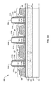
- silicide and contact formation processes are carried out on structure 375 of FIG. 3D .
- structure 380 includes silicide areas 381 b , 382 a , 382 b , 383 , and 384 a that are respectively formed over the top surfaces of epitaxial raised source/drain (S/D) regions 320 b , 322 a , 322 b , 324 , and 326 a .
- Silicide may be formed by depositing a metal liner material such as nickel over structure 375 ( FIG. 3D ), followed by a thermal anneal process (e.g., approximate 450° C.).
- nickel silicide is formed on the semiconductor material surfaces of the epitaxial raised source/drain (S/D) regions 320 b , 322 a , 322 b , 324 , 326 a . Consequently, silicide areas 381 b , 382 a , 382 b , 383 , and 384 a may, for example, be formed from nickel silicide. In contrast, silicide is not formed over the oxide materials of second spacers 370 - 372 . Thus, the remaining nickel metal liner material not forming the silicide may be subsequently removed from these areas prior to contact (CA) formation.
- CA contact
- silicide formation a portion of the underlying silicon is consumed.
- a portion of the top surfaces of respective epitaxial raised source/drain (S/D) regions 320 b , 322 a , 322 b , 324 , and 326 a is consumed.
- the second spacers 370 - 372 cover the surfaces of the facets 336 , 330 a , 330 b , 332 a , 332 b , 334 corresponding to their respective raised source/drain (S/D) regions 320 b , 322 a , 322 b , 324 , 326 a .
- S/D source/drain
- spacer 370 a covers the surface of facet 336 corresponding to raised source/drain (S/D) region 320 b
- spacer 370 b covers the surface of facet 330 a corresponding to raised source/drain (S/D) region 322 a
- spacer 371 a covers the surface of facet 330 b corresponding to raised source/drain (S/D) region 322 b
- spacers 371 b and 372 a cover the surfaces of respective facet 332 a and 332 b corresponding to raised source/drain (S/D) region 324
- spacer 372 b covers the surface of facet 334 corresponding to raised source/drain (S/D) region 326 a .
- the surfaces of the facets 336 , 330 a , 330 b , 332 a , 332 b , 334 are not exposed to and, therefore, protected from the silicide formation process.
- the facetted areas are exposed, as silicide is formed on the facet, the underlying epitaxially grown S/D material (e.g., SiGe) may be consumed. Consumption of the underlying epitaxially grown S/D material at the facet may effect dopant concentration near the channel and subsequently lead to device operation failure or poor device (e.g., nFET, pFET, etc.) performance. This may particularly apply to regions of the facet where the epitaxially grown S/D material becomes thinner (i.e., near the gate edge).
- the underlying epitaxially grown S/D material e.g., SiGe
- the thinner epitaxial region 385 of the raised source/drain (S/D) region 320 b may be consumed, which may adversely effect dopant concentrations in region 385 .
- This rationale applies to the formation of silicide on remaining facets 330 a , 330 b , 332 a , 332 b , and 334 .
- a contact (CA) dielectric material layer such as silicon oxide or silicon nitride may be deposited, patterned and etched. Dielectric regions 388 are the result of such deposition, photolithographic patterning, and etching processes. As shown, for the contact formation processes, the contact (CA) dielectric material layer (not shown) may be patterned in order to align the contact (CA) regions 390 with both the silicide covered portions of the raised source/drain (S/D) regions 320 b , 322 a , 322 b , 324 , 326 a and the gate electrodes 310 a - 310 c . Once formed, the contact regions 390 may be filed with an electrically conductive material such as tungsten in order to create contacts 392 .
- an electrically conductive material such as tungsten
- FIGS. 4A and 4B illustrate a semiconductor structure 400 that includes a contact strap 402 that connects two individual transistor devices 404 a , 404 b .
- FIG. 4B depicts a cross sectional view (along A-A′) of the semiconductor structure 400 .
- Contact strap 402 connects to both gate structure 406 a of device 404 a and gate structure 406 b of device 404 b .
- the embodiment of FIGS. 4A-4B includes desired facets along their gate edges.
- raised source/drain (S/D) region 408 a of device 404 a includes a desired facetted shape along gate edge region 412 a .
- raised source/drain (S/D) region 410 a of device 404 a includes a desired facetted shape along gate edge region 414 a .
- raised source/drain (S/D) region 408 b of device 404 b includes a desired facetted shape along gate edge region 412 b .
- raised source/drain (S/D) region 410 b of device 404 b includes a desired facetted shape along gate edge region 414 b .
- no facets corresponding to raised source/drain (S/D) regions 408 a and 410 a are desirably formed based on the above-described embodiments.
- spacer material 420 is, however, formed on the substantially vertical shaped (not shown) raised source/drain (S/D) regions 408 a , 410 a along border 416 of device 404 a .
- spacer material 422 is also formed on the substantially vertical shaped raised source/drain (S/D) regions 408 b , 410 b along border 418 of device 404 b.
- FIG. 5 shows a block diagram of an exemplary design flow 900 used for example, in semiconductor IC logic design, simulation, test, layout, and manufacture.
- Design flow 900 includes processes and mechanisms for processing design structures or devices to generate logically or otherwise functionally equivalent representations of the design structures and/or devices described above and shown in FIGS. 3E & 4A .
- the design structure processed and/or generated by design flow 900 may be encoded on machine-readable transmission or storage media to include data and/or instructions that when executed or otherwise processed on a data processing system generate a logically, structurally, mechanically, or otherwise functionally equivalent representation of hardware components, circuits, devices, or systems.
- Design flow 900 may vary depending on the type of representation being designed. For example, a design flow 900 for building an application specific IC (ASIC) may differ from a design flow 900 for designing a standard component or from a design flow 900 for instantiating the design into a programmable array, for example a programmable gate array (PGA) or a field programmable gate array (FPGA) offered by Altera® Inc. or Xilinx® Inc.
- ASIC application specific IC
- PGA programmable gate array
- FPGA field programmable gate array
- FIG. 5 illustrates multiple such design structures including an input design structure 920 that is preferably processed by a design process 910 .
- the design structure 920 comprises design data used in a design process and comprising information describing one or more embodiments of the invention with respect to the structures as shown in FIGS. 3E & 4A .
- the design data in the form of schematics or HDL, a hardware-description language (e.g., Verilog, VHDL, C, etc.) may be embodied on one or more machine readable media.
- design structure 920 may be a text file, numerical data or a graphical representation of the one or more embodiments of the invention, as shown in FIGS. 3E & 4A .
- Design structure 920 may be a logical simulation design structure generated and processed by design process 910 to produce a logically equivalent functional representation of a hardware device.
- Design structure 920 may also or alternatively comprise data and/or program instructions that when processed by design process 910 , generate a functional representation of the physical structure of a hardware device. Whether representing functional and/or structural design features, design structure 920 may be generated using electronic computer-aided design (ECAD) such as implemented by a core developer/designer.
- ECAD electronic computer-aided design
- design structure 920 When encoded on a machine-readable data transmission, gate array, or storage medium, design structure 920 may be accessed and processed by one or more hardware and/or software modules within design process 910 to simulate or otherwise functionally represent an electronic component, circuit, electronic or logic module, apparatus, device, or system such as those shown in FIGS. 3E & 4A .
- design structure 920 may comprise files or other data structures including human and/or machine-readable source code, compiled structures, and computer-executable code structures that when processed by a design or simulation data processing system, functionally simulate or otherwise represent circuits or other levels of hardware logic design.
- Such data structures may include hardware-description language (HDL) design entities or other data structures conforming to and/or compatible with lower-level HDL design languages such as Verilog and VHDL, and/or higher level design languages such as C or C++.
- HDL hardware-description language
- Design process 910 preferably employs and incorporates hardware and/or software modules for synthesizing, translating, or otherwise processing a design/simulation functional equivalent of the components, circuits, devices, or logic structures shown in FIGS. 3E & 4A to generate a netlist 980 which may contain a design structure such as design structure 920 .
- Netlist 980 may comprise, for example, compiled or otherwise processed data structures representing a list of wires, discrete components, logic gates, control circuits, I/O devices, models, etc. that describes the connections to other elements and circuits in an integrated circuit design.
- Netlist 980 may be synthesized using an iterative process in which netlist 980 is resynthesized one or more times depending on design specifications and parameters for the device.
- netlist 980 may be recorded on a machine-readable data storage medium or programmed into a programmable gate array.
- the medium may be a non-volatile storage medium such as a magnetic or optical disk drive, a programmable gate array, a compact flash, or other flash memory. Additionally, or in the alternative, the medium may be a system or cache memory, buffer space, or electrically or optically conductive devices and materials on which data packets may be transmitted and intermediately stored via the Internet, or other networking suitable means.
- Design process 910 may include hardware and software modules for processing a variety of input data structure types including netlist 980 .
- data structure types may reside, for example, within library elements 930 and include a set of commonly used elements, circuits, and devices, including models, layouts, and symbolic representations, for a given manufacturing technology (e.g., different technology nodes, 32 nm, 45 nm, 90 nm, etc.).
- the data structure types may further include design specifications 940 , characterization data 950 , verification data 960 , design rules 970 , and test data files 985 which may include input test patterns, output test results, and other testing information.
- Design process 910 may further include, for example, standard mechanical design processes such as stress analysis, thermal analysis, mechanical event simulation, process simulation for operations such as casting, molding, and die press forming, etc.
- standard mechanical design processes such as stress analysis, thermal analysis, mechanical event simulation, process simulation for operations such as casting, molding, and die press forming, etc.
- One of ordinary skill in the art of mechanical design can appreciate the extent of possible mechanical design tools and applications used in design process 910 without deviating from the scope and spirit of the invention.
- Design process 910 may also include modules for performing standard circuit design processes such as timing analysis, verification, design rule checking, place and route operations, etc.
- Design process 910 employs and incorporates logic and physical design tools such as HDL compilers and simulation model build tools to process design structure 920 together with some or all of the depicted supporting data structures along with any additional mechanical design or data (if applicable), to generate a second design structure 990 comprising second design data embodied on a storage medium in a data format used for the exchange of layout data of integrated circuits and/or symbolic data format (e.g. information stored in a GDSII (GDS2), GL1, OASIS, map files, or any other suitable format for storing such design structures).
- the second design data resides on a storage medium or programmable gate array in a data format used for the exchange of data of mechanical devices and structures (e.g.
- design structure 990 preferably comprises one or more files, data structures, or other computer-encoded data or instructions that reside on transmission or data storage media and that when processed by an ECAD system generate a logically or otherwise functionally equivalent form of one or more of the embodiments of the invention shown in FIGS. 3E & 4A .
- design structure 990 may comprise a compiled, executable HDL simulation model that functionally simulates the devices shown in FIGS. 3E & 4A .
- Design structure 990 may also employ a data format used for the exchange of layout data of integrated circuits and/or symbolic data format (e.g. information stored in a GDSII (GDS2), GL1, OASIS, map files, or any other suitable format for storing such design data structures).
- GDSII GDS2
- GL1 GL1, OASIS, map files, or any other suitable format for storing such design data structures.
- Design structure 990 may comprise information such as, for example, symbolic data, map files, test data files, design content files, manufacturing data, layout parameters, wires, levels of metal, vias, shapes, data for routing through the manufacturing line, and any other data required by a manufacturer or other designer/developer to produce devices or structures as described above and shown in FIGS. 3E & 4A .
- Design structure 990 may then proceed to a stage 995 where, for example, design structure 990 : proceeds to tape-out, is released to manufacturing, is released to a mask house, is sent to another design house, is sent back to the customer, etc.
Landscapes
- Engineering & Computer Science (AREA)
- Power Engineering (AREA)
- Microelectronics & Electronic Packaging (AREA)
- Physics & Mathematics (AREA)
- Condensed Matter Physics & Semiconductors (AREA)
- General Physics & Mathematics (AREA)
- Computer Hardware Design (AREA)
- Manufacturing & Machinery (AREA)
- Ceramic Engineering (AREA)
- Insulated Gate Type Field-Effect Transistor (AREA)
Abstract
Description
Claims (12)
Priority Applications (2)
| Application Number | Priority Date | Filing Date | Title |
|---|---|---|---|
| US13/534,407 US8916443B2 (en) | 2012-06-27 | 2012-06-27 | Semiconductor device with epitaxial source/drain facetting provided at the gate edge |
| US14/533,154 US9437679B2 (en) | 2012-06-27 | 2014-11-05 | Semi-conductor device with epitaxial source/drain facetting provided at the gate edge |
Applications Claiming Priority (1)
| Application Number | Priority Date | Filing Date | Title |
|---|---|---|---|
| US13/534,407 US8916443B2 (en) | 2012-06-27 | 2012-06-27 | Semiconductor device with epitaxial source/drain facetting provided at the gate edge |
Related Child Applications (1)
| Application Number | Title | Priority Date | Filing Date |
|---|---|---|---|
| US14/533,154 Division US9437679B2 (en) | 2012-06-27 | 2014-11-05 | Semi-conductor device with epitaxial source/drain facetting provided at the gate edge |
Publications (2)
| Publication Number | Publication Date |
|---|---|
| US20140001554A1 US20140001554A1 (en) | 2014-01-02 |
| US8916443B2 true US8916443B2 (en) | 2014-12-23 |
Family
ID=49777210
Family Applications (2)
| Application Number | Title | Priority Date | Filing Date |
|---|---|---|---|
| US13/534,407 Expired - Fee Related US8916443B2 (en) | 2012-06-27 | 2012-06-27 | Semiconductor device with epitaxial source/drain facetting provided at the gate edge |
| US14/533,154 Expired - Fee Related US9437679B2 (en) | 2012-06-27 | 2014-11-05 | Semi-conductor device with epitaxial source/drain facetting provided at the gate edge |
Family Applications After (1)
| Application Number | Title | Priority Date | Filing Date |
|---|---|---|---|
| US14/533,154 Expired - Fee Related US9437679B2 (en) | 2012-06-27 | 2014-11-05 | Semi-conductor device with epitaxial source/drain facetting provided at the gate edge |
Country Status (1)
| Country | Link |
|---|---|
| US (2) | US8916443B2 (en) |
Cited By (1)
| Publication number | Priority date | Publication date | Assignee | Title |
|---|---|---|---|---|
| US9735173B1 (en) | 2016-03-17 | 2017-08-15 | International Business Machines Corporation | Reduced parasitic capacitance and contact resistance in extremely thin silicon-on-insulator (ETSOI) devices due to wrap-around structure of source/drain regions |
Families Citing this family (6)
| Publication number | Priority date | Publication date | Assignee | Title |
|---|---|---|---|---|
| US8916443B2 (en) | 2012-06-27 | 2014-12-23 | International Business Machines Corporation | Semiconductor device with epitaxial source/drain facetting provided at the gate edge |
| US10633734B2 (en) * | 2012-10-05 | 2020-04-28 | California Institute Of Technology | Optical sensor for analyte detection |
| US9786755B2 (en) * | 2015-03-18 | 2017-10-10 | Stmicroelectronics (Crolles 2) Sas | Process for producing, from an SOI and in particular an FDSOI type substrate, transistors having gate oxides of different thicknesses, and corresponding integrated circuit |
| JP6673806B2 (en) * | 2016-11-15 | 2020-03-25 | ルネサスエレクトロニクス株式会社 | Semiconductor device |
| US20180337033A1 (en) * | 2017-05-16 | 2018-11-22 | Globalfoundries Inc. | Novel approach to improve sdb device performance |
| US11355401B1 (en) | 2021-02-11 | 2022-06-07 | International Business Machines Corporation | Field effect transistor |
Citations (13)
| Publication number | Priority date | Publication date | Assignee | Title |
|---|---|---|---|---|
| US4998150A (en) * | 1988-12-22 | 1991-03-05 | Texas Instruments Incorporated | Raised source/drain transistor |
| US6593618B2 (en) | 2000-11-28 | 2003-07-15 | Kabushiki Kaisha Toshiba | MIS semiconductor device having an elevated source/drain structure |
| US20060157797A1 (en) * | 2005-01-06 | 2006-07-20 | Yasushi Tateshita | Insulated gate field-effect transistor and a method of manufacturing the same |
| US20060284269A1 (en) | 2001-03-23 | 2006-12-21 | Micron Technology, Inc. | Method for forming raised structures by controlled selective epitaxial growth of facet using spacer |
| US20070132057A1 (en) * | 2005-12-08 | 2007-06-14 | Giuseppe Curello | Active region spacer for semiconductor devices and method to form the same |
| US7423323B2 (en) | 2003-04-03 | 2008-09-09 | Taiwan Semiconductor Manufacturing Company, Ltd. | Semiconductor device with raised segment |
| US7439568B2 (en) | 2005-02-10 | 2008-10-21 | International Business Machines Corporation | Vertical body-contacted SOI transistor |
| US7449378B2 (en) | 2005-07-21 | 2008-11-11 | International Business Machines Corporation | Structure and method for improved stress and yield in pFETS with embedded SiGe source/drain regions |
| US20090315120A1 (en) | 2008-06-24 | 2009-12-24 | Lucian Shifren | Raised facet- and non-facet 3d source/drain contacts in mosfets |
| US20100258869A1 (en) * | 2009-04-10 | 2010-10-14 | Hitachi, Ltd. | Semiconductor device and manufacturing method thereof |
| WO2011064891A1 (en) * | 2009-11-30 | 2011-06-03 | 富士通セミコンダクター株式会社 | Method of producing semiconductor device, and method of producing dynamic threshold transistor |
| US20110193167A1 (en) * | 2010-02-11 | 2011-08-11 | Taiwan Semiconductor Manufacturing Company, Ltd. | Self-Aligned Two-Step STI Formation Through Dummy Poly Removal |
| US20110254090A1 (en) | 2010-04-14 | 2011-10-20 | International Business Machines Corporation | Raised source/drain structure for enhanced strain coupling from stress liner |
Family Cites Families (13)
| Publication number | Priority date | Publication date | Assignee | Title |
|---|---|---|---|---|
| US6160299A (en) * | 1997-08-29 | 2000-12-12 | Texas Instruments Incorporated | Shallow-implant elevated source/drain doping from a sidewall dopant source |
| DE10219107B4 (en) * | 2002-04-29 | 2011-03-31 | Globalfoundries Inc. | An improved backside contact SOI transistor element and method of making the same and method of making an ohmic contact on a substrate |
| US7195985B2 (en) * | 2005-01-04 | 2007-03-27 | Intel Corporation | CMOS transistor junction regions formed by a CVD etching and deposition sequence |
| US7262109B2 (en) * | 2005-08-03 | 2007-08-28 | Texas Instruments Incorporated | Integrated circuit having a transistor level top side wafer contact and a method of manufacture therefor |
| JP5178103B2 (en) * | 2007-09-12 | 2013-04-10 | 株式会社東芝 | Semiconductor device and manufacturing method thereof |
| EP2120266B1 (en) * | 2008-05-13 | 2015-10-28 | Imec | Scalable quantum well device and method for manufacturing the same |
| US8299546B2 (en) * | 2010-03-25 | 2012-10-30 | International Business Machines Corporation | Semiconductor devices with vertical extensions for lateral scaling |
| US20130026575A1 (en) * | 2011-07-28 | 2013-01-31 | Synopsys, Inc. | Threshold adjustment of transistors by controlled s/d underlap |
| US8623713B2 (en) * | 2011-09-15 | 2014-01-07 | International Business Machines Corporation | Trench isolation structure |
| US8440552B1 (en) * | 2012-01-09 | 2013-05-14 | International Business Machines Corporation | Method to form low series resistance transistor devices on silicon on insulator layer |
| US8828831B2 (en) * | 2012-01-23 | 2014-09-09 | International Business Machines Corporation | Epitaxial replacement of a raised source/drain |
| US8658486B2 (en) * | 2012-05-23 | 2014-02-25 | International Business Machines Corporation | Forming facet-less epitaxy with a cut mask |
| US8916443B2 (en) | 2012-06-27 | 2014-12-23 | International Business Machines Corporation | Semiconductor device with epitaxial source/drain facetting provided at the gate edge |
-
2012
- 2012-06-27 US US13/534,407 patent/US8916443B2/en not_active Expired - Fee Related
-
2014
- 2014-11-05 US US14/533,154 patent/US9437679B2/en not_active Expired - Fee Related
Patent Citations (14)
| Publication number | Priority date | Publication date | Assignee | Title |
|---|---|---|---|---|
| US4998150A (en) * | 1988-12-22 | 1991-03-05 | Texas Instruments Incorporated | Raised source/drain transistor |
| US6593618B2 (en) | 2000-11-28 | 2003-07-15 | Kabushiki Kaisha Toshiba | MIS semiconductor device having an elevated source/drain structure |
| US20060284269A1 (en) | 2001-03-23 | 2006-12-21 | Micron Technology, Inc. | Method for forming raised structures by controlled selective epitaxial growth of facet using spacer |
| US7423323B2 (en) | 2003-04-03 | 2008-09-09 | Taiwan Semiconductor Manufacturing Company, Ltd. | Semiconductor device with raised segment |
| US20060157797A1 (en) * | 2005-01-06 | 2006-07-20 | Yasushi Tateshita | Insulated gate field-effect transistor and a method of manufacturing the same |
| US7439568B2 (en) | 2005-02-10 | 2008-10-21 | International Business Machines Corporation | Vertical body-contacted SOI transistor |
| US7449378B2 (en) | 2005-07-21 | 2008-11-11 | International Business Machines Corporation | Structure and method for improved stress and yield in pFETS with embedded SiGe source/drain regions |
| US20070132057A1 (en) * | 2005-12-08 | 2007-06-14 | Giuseppe Curello | Active region spacer for semiconductor devices and method to form the same |
| US20090315120A1 (en) | 2008-06-24 | 2009-12-24 | Lucian Shifren | Raised facet- and non-facet 3d source/drain contacts in mosfets |
| US20100258869A1 (en) * | 2009-04-10 | 2010-10-14 | Hitachi, Ltd. | Semiconductor device and manufacturing method thereof |
| WO2011064891A1 (en) * | 2009-11-30 | 2011-06-03 | 富士通セミコンダクター株式会社 | Method of producing semiconductor device, and method of producing dynamic threshold transistor |
| US20130210207A1 (en) * | 2009-11-30 | 2013-08-15 | Fujitsu Semiconductor Limited | Fabrication method of semiconductor device and fabrication method of dynamic threshold transistor |
| US20110193167A1 (en) * | 2010-02-11 | 2011-08-11 | Taiwan Semiconductor Manufacturing Company, Ltd. | Self-Aligned Two-Step STI Formation Through Dummy Poly Removal |
| US20110254090A1 (en) | 2010-04-14 | 2011-10-20 | International Business Machines Corporation | Raised source/drain structure for enhanced strain coupling from stress liner |
Non-Patent Citations (5)
| Title |
|---|
| IP.Com, "CMOS with dual in-situ doped raised source/drain Structures With Single Critical Mask and Method of forming CMOS with dual in-situ doped raised source/drain Structures", IPCOM000203535D, Jan. 27, 2011, pp. 1-3. |
| IP.Com, "Stressed Limited Oxidation for Forming Faceted Raised Source/Drain MOSFET Structures", IPCOM000152417D, May 2, 2007, p. 1-2. |
| K. Cheng et al., "Extremely Thin SOI (ETSOI) Technology: Past, Present, and Future", 2010 IEEE International SOI Conference, Oct. 2010, 4 pages. * |
| Mazure, C. et al., "Facet engineered elevated source/drain by selective Si epitaxy for 0.35 micron MOSFETS," Dec. 13-16, 1992, Electron Devices Meeting 1992, IEDM,Technical Digest, International, vol., No., pp. 853-856. * |
| Rodder, "Raised Source/Drain MOSFET with Dual Sidewall Spacers", IEEE Electron Device Letters, vol. 12, No. 3, Mar. 1991, pp. 89-91. |
Cited By (3)
| Publication number | Priority date | Publication date | Assignee | Title |
|---|---|---|---|---|
| US9735173B1 (en) | 2016-03-17 | 2017-08-15 | International Business Machines Corporation | Reduced parasitic capacitance and contact resistance in extremely thin silicon-on-insulator (ETSOI) devices due to wrap-around structure of source/drain regions |
| US9917199B2 (en) | 2016-03-17 | 2018-03-13 | International Business Machines Corporation | Method for reduced parasitic capacitance and contact resistance in extremely thin silicon-on-insulator (ETSOI) devices due to wrap-around structure of source/drain regions |
| US10170628B2 (en) | 2016-03-17 | 2019-01-01 | International Business Machines Corporation | Method for forming an extremely thin silicon-on-insulator (ETSOI) device having reduced parasitic capacitance and contact resistance due to wrap-around structure of source/drain regions |
Also Published As
| Publication number | Publication date |
|---|---|
| US20150061021A1 (en) | 2015-03-05 |
| US20140001554A1 (en) | 2014-01-02 |
| US9437679B2 (en) | 2016-09-06 |
Similar Documents
| Publication | Publication Date | Title |
|---|---|---|
| US10170587B2 (en) | Heterogeneous source drain region and extension region | |
| US9437679B2 (en) | Semi-conductor device with epitaxial source/drain facetting provided at the gate edge | |
| US9105741B2 (en) | Method of replacement source/drain for 3D CMOS transistors | |
| US9263449B2 (en) | FinFET and fin-passive devices | |
| US8932918B2 (en) | FinFET with self-aligned punchthrough stopper | |
| US20130270638A1 (en) | Strained soi finfet on epitaxially grown box | |
| US20150064855A1 (en) | Finfet with dielectric isolation by silicon-on-nothing and method of fabrication | |
| US9966374B2 (en) | Semiconductor device with gate structures having low-K spacers on sidewalls and electrical contacts therebetween | |
| US20140167163A1 (en) | Multi-Fin FinFETs with Epitaxially-Grown Merged Source/Drains | |
| US9620506B2 (en) | Silicon-on-nothing transistor semiconductor structure with channel epitaxial silicon region | |
| US8772149B2 (en) | FinFET structure and method to adjust threshold voltage in a FinFET structure | |
| CN111106111B (en) | Semiconductor device, method of manufacturing the same, and electronic apparatus including the same | |
| US9620507B2 (en) | Silicon-on-nothing transistor semiconductor structure with channel epitaxial silicon-germanium region | |
| US9318489B2 (en) | Complex circuits utilizing fin structures | |
| WO2013000268A1 (en) | Semiconductor structure and manufacturing method thereof | |
| US20170221766A1 (en) | Semiconductor device and method of manufacturing the same | |
| KR102155327B1 (en) | Field effect transistor and methods for manufacturing the same | |
| US9224607B2 (en) | Dual epitaxy region integration | |
| US9450094B1 (en) | Semiconductor process and fin-shaped field effect transistor | |
| KR102502370B1 (en) | Semiconductor device and method | |
| US20150035076A1 (en) | Self-Aligned Gate Electrode Diffusion Barriers | |
| CN111916501A (en) | Device with ferroelectric or negative capacitance material, method of manufacturing the same, and electronic apparatus |
Legal Events
| Date | Code | Title | Description |
|---|---|---|---|
| AS | Assignment |
Owner name: INTERNATIONAL BUSINESS MACHINES CORPORATION, NEW Y Free format text: ASSIGNMENT OF ASSIGNORS INTEREST;ASSIGNORS:ADAM, THOMAS N.;CHENG, KANGGUO;DORIS, BRUCE B.;AND OTHERS;SIGNING DATES FROM 20120619 TO 20120626;REEL/FRAME:028452/0496 |
|
| STCF | Information on status: patent grant |
Free format text: PATENTED CASE |
|
| AS | Assignment |
Owner name: GLOBALFOUNDRIES U.S. 2 LLC, NEW YORK Free format text: ASSIGNMENT OF ASSIGNORS INTEREST;ASSIGNOR:INTERNATIONAL BUSINESS MACHINES CORPORATION;REEL/FRAME:036550/0001 Effective date: 20150629 |
|
| AS | Assignment |
Owner name: GLOBALFOUNDRIES INC., CAYMAN ISLANDS Free format text: ASSIGNMENT OF ASSIGNORS INTEREST;ASSIGNORS:GLOBALFOUNDRIES U.S. 2 LLC;GLOBALFOUNDRIES U.S. INC.;REEL/FRAME:036779/0001 Effective date: 20150910 |
|
| FEPP | Fee payment procedure |
Free format text: MAINTENANCE FEE REMINDER MAILED (ORIGINAL EVENT CODE: REM.) |
|
| FEPP | Fee payment procedure |
Free format text: SURCHARGE FOR LATE PAYMENT, LARGE ENTITY (ORIGINAL EVENT CODE: M1554); ENTITY STATUS OF PATENT OWNER: LARGE ENTITY |
|
| MAFP | Maintenance fee payment |
Free format text: PAYMENT OF MAINTENANCE FEE, 4TH YEAR, LARGE ENTITY (ORIGINAL EVENT CODE: M1551); ENTITY STATUS OF PATENT OWNER: LARGE ENTITY Year of fee payment: 4 |
|
| AS | Assignment |
Owner name: ALSEPHINA INNOVATIONS INC., CANADA Free format text: ASSIGNMENT OF ASSIGNORS INTEREST;ASSIGNOR:GLOBALFOUNDRIES INC.;REEL/FRAME:049612/0211 Effective date: 20181126 |
|
| AS | Assignment |
Owner name: GLOBALFOUNDRIES INC., CAYMAN ISLANDS Free format text: RELEASE BY SECURED PARTY;ASSIGNOR:WILMINGTON TRUST, NATIONAL ASSOCIATION;REEL/FRAME:054636/0001 Effective date: 20201117 |
|
| FEPP | Fee payment procedure |
Free format text: MAINTENANCE FEE REMINDER MAILED (ORIGINAL EVENT CODE: REM.); ENTITY STATUS OF PATENT OWNER: LARGE ENTITY |
|
| LAPS | Lapse for failure to pay maintenance fees |
Free format text: PATENT EXPIRED FOR FAILURE TO PAY MAINTENANCE FEES (ORIGINAL EVENT CODE: EXP.); ENTITY STATUS OF PATENT OWNER: LARGE ENTITY |
|
| STCH | Information on status: patent discontinuation |
Free format text: PATENT EXPIRED DUE TO NONPAYMENT OF MAINTENANCE FEES UNDER 37 CFR 1.362 |
|
| FP | Lapsed due to failure to pay maintenance fee |
Effective date: 20221223 |