US8907823B2 - Entropy coding - Google Patents
Entropy coding Download PDFInfo
- Publication number
- US8907823B2 US8907823B2 US13/647,956 US201213647956A US8907823B2 US 8907823 B2 US8907823 B2 US 8907823B2 US 201213647956 A US201213647956 A US 201213647956A US 8907823 B2 US8907823 B2 US 8907823B2
- Authority
- US
- United States
- Prior art keywords
- macroblock
- symbol
- symbols
- predetermined
- bin
- Prior art date
- Legal status (The legal status is an assumption and is not a legal conclusion. Google has not performed a legal analysis and makes no representation as to the accuracy of the status listed.)
- Active, expires
Links
Images


Classifications
-
- H—ELECTRICITY
- H03—ELECTRONIC CIRCUITRY
- H03M—CODING; DECODING; CODE CONVERSION IN GENERAL
- H03M7/00—Conversion of a code where information is represented by a given sequence or number of digits to a code where the same, similar or subset of information is represented by a different sequence or number of digits
- H03M7/30—Compression; Expansion; Suppression of unnecessary data, e.g. redundancy reduction
- H03M7/40—Conversion to or from variable length codes, e.g. Shannon-Fano code, Huffman code, Morse code
- H03M7/4006—Conversion to or from arithmetic code
-
- H—ELECTRICITY
- H03—ELECTRONIC CIRCUITRY
- H03M—CODING; DECODING; CODE CONVERSION IN GENERAL
- H03M7/00—Conversion of a code where information is represented by a given sequence or number of digits to a code where the same, similar or subset of information is represented by a different sequence or number of digits
- H03M7/30—Compression; Expansion; Suppression of unnecessary data, e.g. redundancy reduction
- H03M7/40—Conversion to or from variable length codes, e.g. Shannon-Fano code, Huffman code, Morse code
- H03M7/42—Conversion to or from variable length codes, e.g. Shannon-Fano code, Huffman code, Morse code using table look-up for the coding or decoding process, e.g. using read-only memory
-
- H04N19/00521—
-
- H04N19/00951—
-
- H—ELECTRICITY
- H04—ELECTRIC COMMUNICATION TECHNIQUE
- H04N—PICTORIAL COMMUNICATION, e.g. TELEVISION
- H04N19/00—Methods or arrangements for coding, decoding, compressing or decompressing digital video signals
- H04N19/10—Methods or arrangements for coding, decoding, compressing or decompressing digital video signals using adaptive coding
- H04N19/102—Methods or arrangements for coding, decoding, compressing or decompressing digital video signals using adaptive coding characterised by the element, parameter or selection affected or controlled by the adaptive coding
- H04N19/129—Scanning of coding units, e.g. zig-zag scan of transform coefficients or flexible macroblock ordering [FMO]
-
- H—ELECTRICITY
- H04—ELECTRIC COMMUNICATION TECHNIQUE
- H04N—PICTORIAL COMMUNICATION, e.g. TELEVISION
- H04N19/00—Methods or arrangements for coding, decoding, compressing or decompressing digital video signals
- H04N19/10—Methods or arrangements for coding, decoding, compressing or decompressing digital video signals using adaptive coding
- H04N19/134—Methods or arrangements for coding, decoding, compressing or decompressing digital video signals using adaptive coding characterised by the element, parameter or criterion affecting or controlling the adaptive coding
- H04N19/162—User input
-
- H—ELECTRICITY
- H04—ELECTRIC COMMUNICATION TECHNIQUE
- H04N—PICTORIAL COMMUNICATION, e.g. TELEVISION
- H04N19/00—Methods or arrangements for coding, decoding, compressing or decompressing digital video signals
- H04N19/42—Methods or arrangements for coding, decoding, compressing or decompressing digital video signals characterised by implementation details or hardware specially adapted for video compression or decompression, e.g. dedicated software implementation
- H04N19/436—Methods or arrangements for coding, decoding, compressing or decompressing digital video signals characterised by implementation details or hardware specially adapted for video compression or decompression, e.g. dedicated software implementation using parallelised computational arrangements
-
- H—ELECTRICITY
- H04—ELECTRIC COMMUNICATION TECHNIQUE
- H04N—PICTORIAL COMMUNICATION, e.g. TELEVISION
- H04N19/00—Methods or arrangements for coding, decoding, compressing or decompressing digital video signals
- H04N19/90—Methods or arrangements for coding, decoding, compressing or decompressing digital video signals using coding techniques not provided for in groups H04N19/10-H04N19/85, e.g. fractals
- H04N19/91—Entropy coding, e.g. variable length coding [VLC] or arithmetic coding
Definitions
- the present invention relates to entropy coding and may be used in applications such as, for example, video and audio compression.
- the present invention describes a new method and apparatus for entropy encoding and decoding of discrete data.
- Entropy coding in general, can be considered as the most generic form of lossless data compression.
- Lossless compression aims to represent discrete data with fewer bits than needed for the original data representation but without any loss of information.
- Discrete data can be given in the form of text, graphics, images, video, audio, speech, facsimile, medical data, meteorological data, financial data, or any other form of digital data.
- any data source is considered to be given as a sequence of source symbols that takes values in a given m-ary alphabet and that is characterized by a corresponding (discrete) probability distribution ⁇ p 1 , . . . , p m ⁇ .
- p 1 probability distribution
- p m probability distribution
- Huffman codes and arithmetic codes are well-known examples of practical codes capable of approximating the entropy limit (in a certain sense).
- Huffman codes are relatively easy to construct.
- the most attractive property of Huffman codes is that its implementation can be efficiently realized by the use of variable-length code (VLC) tables.
- VLC variable-length code
- Huffman codes in the case of having a dominant alphabet value with p k >0.5, the redundancy of the corresponding Huffman code (without using any alphabet extension such as run length coding) may be quite substantial.
- Another shortcoming of Huffman codes is given by the fact that in case of dealing with higher-order probability modeling, multiple sets of VLC tables may be necessitated.
- Arithmetic coding while being substantially more complex than VLC, offers the advantage of a more consistent and adequate handling when coping with adaptive and higher-order probability modeling as well as with the case of highly skewed probability distributions.
- this characteristic basically results from the fact that arithmetic coding provides a mechanism, at least conceptually, to map any given value of probability estimate in a more or less direct way to a portion of the resulting codeword. Being provided with such an interface, arithmetic coding allows for a clean separation between the tasks of probability modeling and probability estimation, on the one hand, and the actual entropy coding, i.e., mapping of a symbols to codewords, on the other hand.
- an encoder for encoding a sequence of symbols may have: an assigner configured to assign a number of parameters to each symbol of the sequence of symbols based on information contained within previous symbols of the sequence of symbols; a plurality of entropy encoders each of which is configured to convert the symbols forwarded to the respective entropy encoder into a respective bitstream; and a selector configured to forward each symbol to a selected one of the plurality of entropy encoders, the selection depending on the number of parameters assigned to the respective symbol.
- a method for encoding a sequence of symbols may have the steps of: assigning a number of parameters to each symbol of the sequence of symbols based on information contained within previous symbols of the sequence of symbols; and forwarding each symbol to a selected one of a plurality of entropy encoders, the selection depending on the number of parameters assigned to the respective symbol, and each of the plurality of entropy encoders being configured to convert symbols forwarded to the respective entropy encoder into a respective bitstream.
- a decoder for reconstructing a sequence of symbols may have: a plurality of entropy decoders, each of which is configured to convert a respective bitstream into symbols; an assigner configured to assign a number of parameters to each symbol of a sequence of symbols to be reconstructed based on information contained within previously reconstructed symbols of the sequence of symbols; and a selector configured to retrieve each symbol of the sequence of symbols to be reconstructed from a selected one of the plurality of entropy decoders, the selection depending on the number of parameters defined to the respective symbol.
- Another embodiment may have a device for decoding a sequence of symbols sequentially representing syntax elements of a significance mapping and then symbol representations of values of transform coefficients being unequal to zero for blocks of (video) pictures containing transform coefficients being unequal to zero, wherein the syntax elements of the significance mapping specify for the positions of the transform coefficients in a scan order as to whether at the respective position a transform coefficient being unequal to zero or not, and the symbol representations of values of transform coefficients being unequal to zero are represented by the sequence of symbols in a reverse scan order—starting from the last transform coefficient being unequal to zero, the device being configured to reconstruct the sequence of symbols using an inventive decoder.
- an apparatus for entropy decoding entropy-encoded information symbols the entropy-encoded information symbols being produced by entropy encoding a symbol of a sequence of symbols based on probability information for the symbol, the symbol being part of a symbol set, wherein the probability information for the symbol is derived based on a context of the symbol, the context including one or more context symbols processed earlier, and wherein, for entropy encoding the start symbol, an initialization probability information was used, the initialization probability information being based on an estimation of a symbol statistics relating to a start symbol and being determined such that an initialization probability distribution is different from an equi-probable distribution for all symbols of the symbol set
- an inventive decoder for reconstructing the sequence of symbols the decoder being configured to obtain the probability information having been used when entropy encoding the sequence of information symbols, the decoder including an initializer for obtaining the initialization probability information having been used when entropy encoding the start
- a method for reconstructing a sequence of symbols may have the steps of: assigning a number of parameters to each symbol of a sequence of symbols to be reconstructed based on information contained within previously reconstructed symbols of the sequence of symbols; and retrieving each symbol of the sequence of symbols to be reconstructed from a selected one of a plurality of entropy decoders, the selection depending on the number of parameters defined to the respective symbol, and each of the plurality of entropy decoders being configured to convert a respective bitstream into symbols.
- Another embodiment may have a computer readable digital storage medium having stored thereon a computer program having a program code for performing, when running on a computer, one of the inventive methods.
- An encoder for encoding a sequence of symbols comprises an assigner configured to assign a number of parameters to each symbol of the sequence of symbols based on information contained within previous symbols of the sequence of symbols; a plurality of entropy encoders each of which is configured to convert the symbols forwarded to the respective entropy encoder into a respective bitstream; and a selector configured to forward each symbol to a selected one of the plurality of entropy encoders, the selection depending on the number of parameters assigned to the respective symbol.
- a decoder for reconstructing a sequence of symbols comprises a plurality of entropy decoders, each of which is configured to convert a respective bitstream into symbols; an assigner configured to assign a number of parameters to each symbol of a sequence of symbols to be reconstructed based on information contained within previously reconstructed symbols of the sequence of symbols; and a selector configured to retrieve each symbol of the sequence of symbols to be reconstructed from a selected one of the plurality of entropy decoders, the selection depending on the number of parameters defined to the respective symbol.
- Embodiments of an entropy encoding algorithm are described in which a sequence of arbitrary source symbols is mapped onto two or more partial bitstreams, and a decoding algorithm, in which the original source symbols are decoded from the two or more partial bitstreams.
- the source symbols are first binarized (if they don't already represent binary symbols) and each bin of the binarizations is associated with a set of parameters.
- the associated parameters are then mapped onto a small set of indices and all bins that are associated with a particular index are coded by a particular binary entropy encoder and the corresponding codeword or codewords are written to a particular partial bitstream.
- the source symbols are decoded by requests for source symbols.
- the same binarization scheme as for the encoder is used to convert these request for source symbols into requests for bins, and each request for a bin is associated with the same set of parameters as the corresponding bin at the encoder side.
- the associated parameters are again mapped onto a small set of indices, where the mapping is the same as at the encoder side.
- all bin requests that are associated with a particular index are decoded by a particular binary entropy decoder, which reads a codeword or multiple codewords from the corresponding partial bitstream.
- the encoders and decoders are configured in a way that different binary entropy encoders and decoders use different coding algorithms (i.e., a different mapping between bin sequences and codewords).
- the set of associated parameters represents a measure for the probability of one of the two bin values for a particular bin (or a set of equivalent measures).
- the measure for the probability can for example represent a probability state, which can be represented by a value of a set of N values.
- the probability estimation is decoupled from the actual coding of the bins.
- the probability measure is then mapped onto a probability index, by which the encoding and decoding of a bin is assigned to a particular binary entropy encoder and decoder.
- the mapping of the probability measures to probability indexes can also be varied over time, e.g. in dependence of already transmitted symbols.
- the assignment can be adapted to the number of bins that have been coded with a certain probability measure or probability index in order to ensure that the created partial bitstreams have similar bit rates.
- the number of binary entropy encoders and decoders is less than the number of possible values for the probability measure.
- a large number of possible probability measures, which allows an accurate estimation of the associated probability is mapped onto a small number of probability indices, where each of those is associated with a particular binary entropy encoder and decoder.
- the small number of binary entropy encoders and decoders provides the advantage that the overhead for transmitting the partial bitstream can be kept small and that the synchronization overhead is of encoding and decoding system can be kept small.
- the binary encoders and decoders can be particularly optimized for a representative of the group of probability measures, which allows a high coding efficiency (similar to the best known entropy coding schemes).
- simple encoding and decoding algorithms which may consist of a simple mapping of bin sequences to codewords and vice versa, can be designed for the representatives of the groups of probability measure. This reduces the complexity of the encoding and decoding system, while still providing a high coding efficiency.
- the set of parameters that is associated with a bin consists of a measure for the probability of one of the two bin values and one or more additional parameters.
- FIG. 1 shows a bock diagram of an encoder according to an embodiment
- FIG. 2 shows a bock diagram of an decoder suitable for decoding bitstream generated by the encoder of FIG. 1 , according to an embodiment
- FIG. 3 shows a schematic diagram illustrating a data packet with multiplexed partial bitstreams according to an embodiment
- FIG. 4 shows a schematic diagram illustrating a data packet with an alternative segmentation using fixed-size segments according to a further embodiment
- FIG. 5 shows a bock diagram of an encoder according to an embodiment using partial bitstream interleaving
- FIG. 6 shows a schematic illustrating examples for the status of a codeword buffer at the encoder side of FIG. 5 according to an embodiment
- FIG. 7 shows a bock diagram of a decoder according to an embodiment using partial bitstream interleaving
- FIG. 8 shows a bock diagram of a decoder according to an embodiment using codeword interleaving using a single set of codewords
- FIG. 9 shows a bock diagram of an encoder according to an embodiment using interleaving of fixed-length bit sequences
- FIG. 10 shows a schematic illustrating examples for the status of a global bit buffer at the encoder side of FIG. 9 according to an embodiment
- FIG. 11 shows a bock diagram of a decoder according to an embodiment using interleaving of fixed-length bit sequences
- FIG. 14 shows a graph from which the relative bit rate increase ⁇ (p,C) for optimal codes C given a maximum number of table entries L m may be gathered;
- FIG. 16 shows a schematic diagram illustrating an example for conversion of a ternary choice tree into a full binary choice tree
- FIG. 17 shows a block diagram of a system comprising an encoder (left part) and decoder (right part) according to an embodiment
- FIG. 18 is an illustration of the basic principle of coding transform coefficients according to an embodiment using the entropy coding according to any of the embodiments of FIG. 1 t 17 ,
- FIG. 19 shows two examples for coding the significance mapping (the marked symbols are not transferred).
- FIG. 20 shows binarization for the magnitudes of the transform coefficients (ABS),
- FIG. 21 shows block types and their classification for the H.264/AVC standard
- FIG. 22 shows context modeling for the one-bit symbol CBP4.
- FIG. 23 shows examples of the context modeling for coding the magnitudes of the significant transform coefficients.
- FIG. 24 shows a block diagram of an entropy encoder arrangement according to an application example
- FIG. 25 shows a detailed diagram of the initializer from FIG. 24 ;
- FIG. 26 shows a sequence of steps for calculating a reference index to reference an initialization probability information table including probability information for the least probable symbol (LPS) and a value of the corresponding most probable symbol (MPS) as initialization probability information;
- LPS least probable symbol
- MPS most probable symbol
- FIG. 27 shows a schematic block diagram of an entropy decoder arrangement according to an application example
- FIG. 28 shows a high-level block diagram of a coding environment
- FIG. 29 shows a block diagram of the entropy coding part of the coding environment of FIG. 28 ;
- FIG. 30 shows a schematic diagram illustrating the spatial subdivision of a picture or video frame into macroblock pairsn
- FIG. 31 a shows a schematic diagram illustrating the frame mode, in accordance with an embodiment of the present invention.
- FIG. 31 b shows a schematic diagram illustrating the field mode, in accordance with an embodiment of the present invention.
- FIG. 32 shows a flow diagram illustrating the encoding of syntax elements with context assignments based on neighboring syntax elements in accordance with an embodiment of the present invention.
- FIG. 33 shows a flow diagram illustrating the binary entropy coding of the syntax elements based on the context model to which it is assigned in accordance with an embodiment of the present invention.
- FIG. 34 shows a schematic diagram illustrating the addressing scheme of the macroblocks in accordance with an embodiment of the present invention.
- FIG. 35 shows a table illustrating how to obtain the macroblock address mbAddrN indicating the macroblock containing a sample having coordinates xN and yN relative to the upper-left sample of a current macroblock and, additionally, the y coordinate yM for the sample in the macroblock mbAddrN for that sample, dependent on the sample being arranged beyond the top or the left border of the current macroblock, the current macroblock being frame or field coded, and the current macroblock being the top or the bottom macroblock of the current macroblock pair, and, eventually, the macroblock mbAddrA being frame or field coded and the line in which the sample lies having an odd or even line number yN.
- FIG. 36 shows a schematic illustrating macroblock partitions, sub-macroblock partitions, macroblock partitions scans, and sub-macroblock partition scans.
- FIG. 37 shows a high-level block diagram of a decoding environment in which the present invention may be employed.
- FIG. 38 shows a flow diagram illustrating the decoding of the syntax elements coded as shown in FIGS. 32 and 33 from the coded bit stream;
- FIG. 39 shows a flow diagram illustrating the entropy decoding process and the decoding process of FIG. 3 ;
- FIG. 40 shows a basic coding structure for the emerging H.264/AVC video encoder for a macroblock.
- FIG. 41 illustrates a context template consisting of two neighboring syntax elements A and B to the left and on the top of the current syntax element C.
- FIG. 42 shows an illustration of the subdivision of a picture into slices.
- FIG. 43 shows, to the left, intra — 4 ⁇ 4 prediction conducted for samples a-p of a block using samples A_Q, and to the right, “prediction directions for intra — 4 ⁇ 4 prediction.
- FIG. 44 a part of the binarization coding tree related to the binarization scheme FIG. 46 ;
- FIG. 45 a schematic diagram illustrating the binarization of an absolute data value
- FIG. 46 table showing bin strings into which an absolute value is binarized
- FIG. 47 table showing bin strings into which an absolute value is binarized
- FIG. 48 shows a pseudo-C code for performing a binarization
- FIG. 49 shows a schematic diagram illustrating the decoding of an entropy coded bit stream into a data value
- FIG. 50 shows a schematic diagram illustrating the recovering of a data value from a binarization of the data value
- FIG. 51 shows a schematic diagram illustrating the extraction with regard to the suffix part in the process of FIG. 50 ;
- FIG. 52 shows a flow diagram illustrating the encoding of the syntax element mb_field_decoding_flag
- FIG. 53 flow diagram illustrating a process of assigning context models to the mb_field_decoding_flags
- FIG. 54 shows a flow diagram illustrating the decoding of the syntax element mb_field_decoding_flag from the coded bit stream as derived by the encoding scheme of FIG. 52 ;
- FIG. 55 shows a schematic flow diagram illustrating the encoding of a video frame or picture
- FIG. 56 illustrating the different scanning patterns used for field coded macroblocks and frame coded macroblocks.
- FIG. 57 shows a table illustrating a significance map as obtained from the exemplarily chosen transform coefficient levels
- FIG. 58 shows a flow diagram illustrating the encoding of the syntax elements last_significant_coeff_flag and significant_coeff_flag in accordance with an embodiment of the present invention
- FIG. 59 shows a pseudo C-code illustrating the parsing process on decoder side
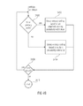
- FIG. 60 shows a flow diagram illustrating the decoding of the syntax elements significant_coeff_flag and last_significant_coeff_flag from the coded bit stream as derived by the encoding scheme of FIG. 58 ;
- FIGS. 61 a,b schematically show the process of decoding a run of MPS for an entropy encoder/decoder pair in accordance with an embodiment
- FIG. 62 schematically shows an example for the quantization of the interval width according to an embodiment.
- each source symbol 1 is associated with a category of a set of one or more categories.
- the categories can specify the type of the source symbol.
- a separate category may be associated with macroblock coding modes, block coding modes, reference picture indices, motion vector differences, subdivision flags, coded block flags, quantization parameters, transform coefficient levels, etc.
- different categorizations of source symbols are possible.
- each source symbol can take a value of a finite or countable infinite set of values, where the set of possible source symbol values can differ for different source symbol categories.
- the source symbols 1 are converted into ordered sets of binary decisions and these binary decisions are then processed by simple binary coding algorithms. Therefore, the binarizer 2 bijectively maps the value of each source symbol 1 onto a sequence (or string) of bins 3 .
- the sequence of bins 3 represents a set of ordered binary decisions.
- Each bin 3 or binary decision can take one value of a set of two values, e.g. one of the values 0 and 1.
- the binarization scheme can be different for different source symbol categories.
- the binarization scheme for a particular source symbol category can depend on the set of possible source symbol values and/or other properties of the source symbols for the particular category.
- Table 1 illustrates three example binarization schemes for countable infinite sets. Binarization schemes for countable infinite sets can also be applied for finite sets of symbol values. In particular for large finite sets of symbols values, the inefficiency (resulting from unused sequences of bins) can be negligible, but the universality of such binarization schemes provides an advantage in terms of complexity and memory requirements. For small finite sets of symbol values, it is often advantageous (in terms of coding efficiency) to adapt the binarization scheme to the number of possible symbol values.
- Table 2 illustrates three example binarization schemes for finite sets of 8 values.
- Binarization schemes for finite sets can be derived from the universal binarization schemes for countable infinite sets by modifying some sequences of bins in a way that the finite sets of bin sequences represent a redundancy-free code (and potentially reordering the bin sequences).
- the truncated unary binarization scheme in Table 2 was created by modifying the bin sequence for the source symbol 7 of the universal unary binarization (see Table 1).
- the truncated and reordered Exp-Golomb binarization of order 0 in Table 2 was created by modifying the bin sequence for the source symbol 7 of the universal Exp-Golomb order 0 binarization (see Table 1) and by reordering the bin sequences (the truncated bin sequence for symbol 7 was assigned to symbol 1 ).
- the truncated bin sequence for symbol 7 was assigned to symbol 1 .
- Binarization examples for finite sets truncated and truncated unary reordered Exp-Golomb non-systematic symbol value binarization order 0 binarization binarization 0 1 1 000 1 01 000 001 2 001 010 01 3 0001 011 1000 4 0000 1 0010 0 1001 5 0000 01 0010 1 1010 6 0000 001 0011 0 1011 0 7 0000 000 0011 1 1011 1
- the parameter assigner 4 assigns a set of one or more parameters to each bin 3 and outputs the bin with the associated set of parameters 5 .
- the set of parameters is determined in exactly the same way at encoder and decoder.
- the set of parameters may consist of one or more of the following parameters:
- the parameter assigner 4 associates each bin 3 , 5 with a measure for an estimate of the probability for one of the two possible bin values for the current bin. In a further embodiment of the invention, the parameter assigner 4 associates each bin 3 , 5 with a measure for an estimate of the probability for the less probable or more probable bin value for the current bin and an identifier specifying an estimate for which of the two possible bin values represents the less probable or more probable bin value for the current bin. It should be noted that the probability for the less probable or more probable bin value and the identifier specifying which of the two possible bin values represents the less probable or more probable bin value are equivalent measures for the probability of one of the two possible bin values.
- the parameter assigner 4 associates each bin 3 , 5 with a measure for an estimate of the probability for one of the two possible bin values for the current bin and one or more further parameters (which may be one or more of the above listed parameters). In a further embodiment of the invention, the parameter assigner 4 associates each bin 3 , 5 with a measure for an estimate of the probability for the less probable or more probable bin value for the current bin, an identifier specifying an estimate for which of the two possible bin values represents the less probable or more probable bin value for the current bin, and one or more further parameters (which may be one or more of the above listed parameters).
- the parameter assigner 4 determines one or more of the above mentioned probability measures (measure for an estimate of the probability for one of the two possible bin values for the current bin, measure for an estimate of the probability for the less probable or more probable bin value for the current bin, identifier specifying an estimate for which of the two possible bin values represents the less probable or more probable bin value for the current bin) based on a set of one or more already encoded symbols.
- the encoded symbols that are used for determining the probability measures can include one or more already encoded symbols of the same symbol category, one or more already encoded symbols of the same symbol category that correspond to data sets (such as blocks or groups of samples) of neighboring spatial and/or temporal locations (in relation to the data set associated with the current source symbol), or one or more already encoded symbols of different symbol categories that correspond to data sets of the same and/or neighboring spatial and/or temporal locations (in relation to the data set associated with the current source symbol).
- Each bin with an associated set of parameters 5 that is output of the parameter assigner 4 is fed into a bin buffer selector 6 .
- the bin buffer selector 6 potentially modifies the value of the input bin 5 based on the input bin value and the associated parameters 5 and feeds the output bin 7 —with a potentially modified value—into one of two or more bin buffers 8 .
- the bin buffer 8 to which the output bin 7 is sent is determined based on the value of the input bin 5 and/or the value of the associated parameters 5 .
- the bin buffer selector 6 does not modify the value of the bin, i.e., the output bin 7 has the same value as the input bin 5 .
- the bin buffer selector 6 determines the output bin value 7 based on the input bin value 5 and the associated measure for an estimate of the probability for one of the two possible bin values for the current bin.
- the output bin value 7 is set equal to the input bin value 5 if the measure for the probability for one of the two possible bin values for the current bin is less than (or less than or equal to) a particular threshold; if the measure for the probability for one of the two possible bin values for the current bin is greater than or equal to (or greater than) a particular threshold, the output bin value 7 is modified (i.e., it is set to the opposite of the input bin value).
- the output bin value 7 is set equal to the input bin value 5 if the measure for the probability for one of the two possible bin values for the current bin is greater than (or greater than or equal to) a particular threshold; if the measure for the probability for one of the two possible bin values for the current bin is less than or equal to (or less than) a particular threshold, the output bin value 7 is modified (i.e., it is set to the opposite of the input bin value).
- the value of the threshold corresponds to a value of 0.5 for the estimated probability for both possible bin values.
- the bin buffer selector 6 determines the output bin value 7 based on the input bin value 5 and the associated identifier specifying an estimate for which of the two possible bin values represents the less probable or more probable bin value for the current bin.
- the output bin value 7 is set equal to the input bin value 5 if the identifier specifies that the first of the two possible bin values represents the less probable (or more probable) bin value for the current bin, and the output bin value 7 is modified (i.e., it is set to the opposite of the input bin value) if identifier specifies that the second of the two possible bin values represents the less probable (or more probable) bin value for the current bin.
- the bin buffer selector 6 determines the bin buffer 8 to which the output bin 7 is sent based on the associated measure for an estimate of the probability for one of the two possible bin values for the current bin.
- the set of possible values for the measure for an estimate of the probability for one of the two possible bin values is finite and the bin buffer selector 6 contains a table that associates exactly one bin buffer 8 with each possible value for the estimate of the probability for one of the two possible bin values, where different values for the measure for an estimate of the probability for one of the two possible bin values can be associated with the same bin buffer 8 .
- the range of possible values for the measure for an estimate of the probability for one of the two possible bin values is partitioned into a number of intervals
- the bin buffer selector 6 determines the interval index for the current measure for an estimate of the probability for one of the two possible bin values
- the bin buffer selector 6 contains a table that associates exactly one bin buffer 8 with each possible value for the interval index, where different values for the interval index can be associated with the same bin buffer 8 .
- input bins 5 with opposite measures for an estimate of the probability for one of the two possible bin values are fed into the same bin buffer 8 .
- the association of the measure for an estimate of the probability for one of the two possible bin values for the current bin with a particular bin buffer is adapted over time, e.g. in order to ensure that the created partial bitstreams have similar bit rates.
- the bin buffer selector 6 determines the bin buffer 8 to which the output bin 7 is sent based on the associated measure for an estimate of the probability for the less probable or more probable bin value for the current bin.
- the set of possible values for the measure for an estimate of the probability for the less probable or more probable bin value is finite and the bin buffer selector 6 contains a table that associates exactly one bin buffer 8 with each possible value of the estimate of the probability for the less probable or more probable bin value, where different values for the measure for an estimate of the probability for the less probable or more probable bin value can be associated with the same bin buffer 8 .
- the range of possible values for the measure for an estimate of the probability for the less probable or more probable bin value is partitioned into a number of intervals, the bin buffer selector 6 determines the interval index for the current measure for an estimate of the probability for the less probable or more probable bin value, and the bin buffer selector 6 contains a table that associates exactly one bin buffer 8 with each possible value for the interval index, where different values for the interval index can be associated with the same bin buffer 8 .
- the association of the measure for an estimate of the probability for the less probable or more probable bin value for the current bin with a particular bin buffer is adapted over time, e.g. in order to ensure that the created partial bitstreams have similar bit rates.
- Each of the two or more bin buffers 8 is connected with exactly one bin encoder 10 and each bin encoder is only connected with one bin buffer 8 .
- Each bin encoder 10 reads bins from the associated bin buffer 8 and converts a sequence of bins 9 into a codeword 11 , which represents a sequence of bits.
- the bin buffers 8 represent first-in-first-out buffers; bins that are fed later (in sequential order) into a bin buffer 8 are not encoded before bins that are fed earlier (in sequential order) into the bin buffer.
- the codewords 11 that are output of a particular bin encoder 10 are written to a particular partial bitstream 12 .
- the overall encoding algorithm converts source symbols 1 into two or more partial bitstreams 12 , where the number of partial bitstreams is equal to the number of bin buffers and bin encoders.
- a bin encoder 10 converts a variable number of bins 9 into a codeword 11 of a variable number of bits.
- the bin encoding which is done by the bin encoders 10
- the bin encoding and encoding can be optimized (in terms of coding efficiency and/or complexity) for different groups of estimated probabilities.
- this allows a reduction of the encoding/decoding complexity relative to state-of-the-art entropy coding algorithms with similar coding efficiency.
- it allows an improvement of the coding efficiency relative to state-of-the-art entropy coding algorithms with similar encoding/decoding complexity.
- the bin encoders 10 implement different encoding algorithms (i.e.
- the bin encoders 10 implement different encoding algorithms for different groups of measures for an estimate of the probability for the less probable or more probable bin value for the current bin.
- the bin encoders 10 implement different encoding algorithms for different channel protection codes.
- the bin encoders 10 implement different encoding algorithms for different encryption schemes.
- the bin encoders 10 implement different encoding algorithms for different combinations of channel protection codes and groups of measures for an estimate of the probability for one of the two possible bin values 5 for the current bin.
- the bin encoders 10 implement different encoding algorithms for different combinations of channel protection codes and groups of measures for an estimate of the probability for the less probable or more probable bin value 5 for the current bin. In a further embodiment, the bin encoders 10 implement different encoding algorithms for different combinations of encryption schemes and groups of measures for an estimate of the probability for one of the two possible bin values 5 for the current bin. In a further embodiment, the bin encoders 10 implement different encoding algorithms for different combinations of encryption schemes and groups of measures for an estimate of the probability for the less probable or more probable bin value 5 for the current bin.
- the bin encoders 10 or one or more of the bin encoders—represent binary arithmetic encoding engines.
- one or more of the bin encoders represent a binary arithmetic coding engine, wherein the mapping from the representative LPS/LPB probability p LPS of a given bin buffer to a corresponding code interval width R LPS —i.e. the interval subdivision of the internal state of the binary arithmetic coding engine, which is defined by the current interval width R and the current interval offset L, identifying, for example, the lower bound of the code interval—is realized by using a table lookup.
- K representative interval width values ⁇ Q 0 , . . . , Q K ⁇ 1 ⁇ are used for representing R LPS with the choice of K and the representative interval width values ⁇ Q 0 , . . . , Q K ⁇ 1 ⁇ being dependent on the bin buffer.
- arithmetic encoding of a bin may involve the substeps of mapping the current interval width R to a quantization index q with values in ⁇ 0, . . . , K ⁇ 1 ⁇ and performing the interval subdivision by accessing the corresponding partial interval width value Q q from a lookup table with using q as an index.
- each arithmetic coding engine may be separately transmitted, packetized, or stored, or they may be interleaved for the purpose of transmission or storage as described hereinafter.
- a binary arithmetic coding engine 10 could perform the following steps in coding the bins in its bin buffer 8 :
- the bin encoders 10 or one or more of the bin encoders—represent entropy encoders that directly map sequences of input bins 9 onto codewords 10 .
- Such mappings can be efficiently implemented and don't necessitate a complex arithmetic coding engine.
- the inverse mapping of codewords onto sequences of bins (as done in the decoder) have to be unique in order to guarantee perfect decoding of the input sequence, but the mapping of bin sequences 9 onto codewords 10 doesn't necessarily need to be unique, i.e., it is possible that a particular sequence of bins can be mapped onto more than one sequence of codewords.
- the mapping of sequences of input bins 9 onto codewords 10 is bijective.
- the bin encoders 10 or one or more of the bin encoders—represent entropy encoders that directly map variable-length sequences of input bins 9 onto variable-length codewords 10 .
- the output codewords represent redundancy-free codes such as general huffman codes or canonical huffman codes.
- the output codewords represent redundant codes suitable for error detection and error recovery.
- the output codewords represent encryption codes suitable for encrypting the source symbols.
- sequence of bins codewords (bin order is from left to right) (bits order is from left to right) 0000 0000 1 0000 0001 0000 0000 001 0001 0000 01 0010 0000 1 0011 0001 0100 001 0101 01 0110 1 0111 000 10 01 11 001 010 11 011 1000 0 0001 1001 0010 1010 0011 1000 1 0000 0 1011 0000 1
- the bin encoders 10 or one or more of the bin encoders—represent entropy encoders that directly map variable-length sequences of input bins 9 onto fixed-length codewords 10 .
- the bin encoders 10 or one or more of the bin encoders—represent entropy encoders that directly map fixed-length sequences of input bins 9 onto variable-length codewords 10 .
- the decoder according an embodiment of the invention is illustrated in FIG. 2 .
- the decoder performs basically the inverse operations of the encoder, so that the (previously encoded) sequence of source symbols 27 is decoded from a set of two or more partial bitstreams 24 .
- the decoder includes two different process flows: A flow for data requests, which replicates the data flow of the encoder, and a data flow, which represents the inverse of the encoder data flow.
- the dashed arrows represent the data request flow, while the solid arrows represent the data flow.
- the building blocks of the decoder basically replicate the building blocks of the encoder, but implement the inverse operations.
- each request for a new decoded source symbol 13 is associated with a category of a set of one or more categories.
- the category that is associated with a request for a source symbol is the same as the category that was associated with the corresponding source symbol during encoding.
- the binarizer 14 maps the request for a source symbol 13 into one or more requests for a bin that are sent to the parameter assigner 16 .
- the binarizer 14 receives a decoded bin 26 from the bin buffer selector 18 .
- the binarizer 14 compares the received sequence of decoded bins 26 with the bin sequences of a particular binarization scheme for the requested source symbol and, if the received sequence of decoded bins 26 matches the binarization of a source symbol, the binarizer empties its bin buffer and outputs the decoded source symbol as final response to the request for a new decoded symbol.
- the binarizer sends another request for a bin to the parameter assigner until the sequence of decoded bins matches one of the bin sequences of the binarization scheme for the requested source symbol.
- the decoder uses the same binarization scheme that was used for encoding the corresponding source symbol.
- the binarization scheme can be different for different source symbol categories.
- the binarization scheme for a particular source symbol category can depend on the set of possible source symbol values and/or other properties of the source symbols for the particular category.
- the parameter assigner assigns a set of one or more parameters to each request for a bin and sends the request for a bin with the associated set of parameters to the bin buffer selector.
- the set of parameters that are assigned to a requested bin by the parameter assigner is the same that was assigned to the corresponding bin during encoding.
- the set of parameters may consist of one or more of the parameters that are mentioned in the encoder description.
- the parameter assigner 16 associates each request for a bin with a measure for an estimate of the probability for one of the two possible bin values for the current requested bin. In a further embodiment of the invention, the parameter assigner 16 associates each request for a bin with a measure for an estimate of the probability for the less probable or more probable bin value for the current requested bin and an identifier specifying an estimate for which of the two possible bin values represents the less probable or more probable bin value for the current requested bin.
- the parameter assigner 16 associates each request for a bin 15 , 17 with a measure for an estimate of the probability for one of the two possible bin values for the current requested bin and one or more further parameters. In a further embodiment of the invention, the parameter assigner 16 associates each request for a bin 15 , 17 with a measure for an estimate of the probability for the less probable or more probable bin value for the current requested bin, an identifier specifying an estimate for which of the two possible bin values represents the less probable or more probable bin value for the current requested bin, and one or more further parameters (which may one or more of the above listed parameters).
- the parameter assigner 16 determines one or more of the above mentioned probability measures (measure for an estimate of the probability for one of the two possible bin values for the current requested bin, measure for an estimate of the probability for the less probable or more probable bin value for the current requested bin, identifier specifying an estimate for which of the two possible bin values represents the less probable or more probable bin value for the current requested bin) based on a set of one or more already decoded symbols.
- the determination of the probability measures for a particular request for a bin replicates the process at the encoder for the corresponding bin.
- the decoded symbols that are used for determining the probability measures can include one or more already decoded symbols of the same symbol category, one or more already decoded symbols of the same symbol category that correspond to data sets (such as blocks or groups of samples) of neighboring spatial and/or temporal locations (in relation to the data set associated with the current request for a source symbol), or one or more already decoded symbols of different symbol categories that correspond to data sets of the same and/or neighboring spatial and/or temporal locations (in relation to the data set associated with the current request for a source symbol).
- Each request for a bin with an associated set of parameters 17 that is output of the parameter assigner 16 is fed into a bin buffer selector 18 .
- the bin buffer selector 18 Based on the associated set of parameters 17 , the bin buffer selector 18 sends a request for a bin 19 to one of two or more bin buffers 20 and receives a decoded bin 25 from the selected bin buffer 20 .
- the decoded input bin 25 is potentially modified and the decoded output bin 26 —with a potentially modified value—is send to the binarizer 14 as final response to the request for a bin with an associated set of parameters 17 .
- the bin buffer 20 to which the request for a bin is forwarded is selected in the same way as the bin buffer to which the output bin of the bin buffer selector at the encoder side was sent.
- the bin buffer selector 18 determines the bin buffer 20 to which the request for a bin 19 is sent based on the associated measure for an estimate of the probability for one of the two possible bin values for the current requested bin.
- the set of possible values for the measure for an estimate of the probability for one of the two possible bin values is finite and the bin buffer selector 18 contains a table that associates exactly one bin buffer 20 with each possible value of the estimate of the probability for one of the two possible bin values, where different values for the measure for an estimate of the probability for one of the two possible bin values can be associated with the same bin buffer 20 .
- the range of possible values for the measure for an estimate of the probability for one of the two possible bin values is partitioned into a number of intervals, the bin buffer selector 18 determines the interval index for the current measure for an estimate of the probability for one of the two possible bin values, and the bin buffer selector 18 contains a table that associates exactly one bin buffer 20 with each possible value for the interval index, where different values for the interval index can be associated with the same bin buffer 20 .
- requests for bins 17 with opposite measures for an estimate of the probability for one of the two possible bin values are forwarded to the same bin buffer 20 .
- the association of the measure for an estimate of the probability for one of the two possible bin values for the current bin request with a particular bin buffer is adapted over time.
- the bin buffer selector 18 determines the bin buffer 20 to which the request for a bin 19 is sent based on the associated measure for an estimate of the probability for the less probable or more probable bin value for the current requested bin.
- the set of possible values for the measure for an estimate of the probability for the less probable or more probable bin value is finite and the bin buffer selector 18 contains a table that associates exactly one bin buffer 20 with each possible value of the estimate of the probability for the less probable or more probable bin value, where different values for the measure for an estimate of the probability for the less probable or more probable bin value can be associated with the same bin buffer 20 .
- the range of possible values for the measure for an estimate of the probability for the less probable or more probable bin value is partitioned into a number of intervals
- the bin buffer selector 18 determines the interval index for the current measure for an estimate of the probability for the less probable or more probable bin value
- the bin buffer selector 18 contains a table that associates exactly one bin buffer 20 with each possible value for the interval index, where different values for the interval index can be associated with the same bin buffer 20 .
- the association of the measure for an estimate of the probability for the less probable or more probable bin value for the current bin request with a particular bin buffer is adapted over time.
- the bin buffer selector 18 After receiving a decoded bin 25 from the selected bin buffer 20 , the bin buffer selector 18 potentially modifies the input bin 25 and sends the output bin 26 —with a potentially modified value—to the binarizer 14 .
- the input/output bin mapping of the bin buffer selector 18 is the inverse of the input/output bin mapping of the bin buffer selector at the encoder side.
- the bin buffer selector 18 does not modify the value of the bin, i.e., the output bin 26 has the same value as the input bin 25 .
- the bin buffer selector 18 determines the output bin value 26 based on the input bin value 25 and the measure for an estimate of the probability for one of the two possible bin values for the current requested bin that is associated with the request for a bin 17 .
- the output bin value 26 is set equal to the input bin value 25 if the measure for the probability for one of the two possible bin values for the current bin request is less than (or less than or equal to) a particular threshold; if the measure for the probability for one of the two possible bin values for the current bin request is greater than or equal to (or greater than) a particular threshold, the output bin value 26 is modified (i.e., it is set to the opposite of the input bin value).
- the output bin value 26 is set equal to the input bin value 25 if the measure for the probability for one of the two possible bin values for the current bin request is greater than (or greater than or equal to) a particular threshold; if the measure for the probability for one of the two possible bin values for the current bin request is less than or equal to (or less than) a particular threshold, the output bin value 26 is modified (i.e., it is set to the opposite of the input bin value).
- the value of the threshold corresponds to a value of 0.5 for the estimated probability for both possible bin values.
- the bin buffer selector 18 determines the output bin value 26 based on the input bin value 25 and the identifier, specifying an estimate for which of the two possible bin values represents the less probable or more probable bin value for the current bin request, that is associated with the request for a bin 17 .
- the output bin value 26 is set equal to the input bin value 25 if the identifier specifies that the first of the two possible bin values represents the less probable (or more probable) bin value for the current bin request, and the output bin value 26 is modified (i.e., it is set to the opposite of the input bin value) if identifier specifies that the second of the two possible bin values represents the less probable (or more probable) bin value for the current bin request.
- the bin buffer selector sends a request for a bin 19 to one of the two or more bin buffers 20 .
- the bin buffers 20 represent first-in-first-out buffers, which are fed with sequences of decoded bins 21 from the connected bin decoders 22 .
- the bin buffer 20 removes the bin of its content that was first fed into the bin buffer 20 and sends it to the bin buffer selector 18 . Bins that are earlier sent to the bin buffer 20 are earlier removed and sent to the bin buffer selector 18 .
- Each of the two or more bin buffers 20 is connected with exactly one bin decoder 22 and each bin decoder is only connected with one bin buffer 20 .
- Each bin decoder 22 reads codewords 23 , which represent sequences of bits, from a separate partial bitstream 24 .
- the bin decoder converts a codeword 23 into a sequence of bins 21 that is sent to the connected bin buffer 20 .
- the overall decoding algorithm converts two or more partial bitstreams 24 into a number of decoded source symbols, where the number of partial bitstreams is equal to the number of bin buffers and bin decoders and the decoding of source symbols is triggered by requests for new source symbols.
- a bin decoder 22 converts codewords 23 of a variable number of bits into a sequence of a variable number of bins 21 .
- One advantage of embodiments of the invention is that the decoding of bins from the two or more partial bitstreams can be done in parallel (e.g. for different groups of probability measures), which reduces the processing time for several implementations.
- the bin decoding which is done by the bin decoders 22
- the bin encoding and decoding can be optimized (in terms of coding efficiency and/or complexity) for different groups of estimated probabilities.
- this allows a reduction of the encoding/decoding complexity relative to state-of-the-art entropy coding algorithms with similar coding efficiency.
- it allows an improvement of the coding efficiency relative to state-of-the-art entropy coding algorithms with similar encoding/decoding complexity.
- the bin decoders 22 implement different decoding algorithms (i.e.
- the bin decoders 22 implement different decoding algorithms for different groups of measures for an estimate of the probability for the less probable or more probable bin value for the current requested bin.
- the bin decoders 22 implement different decoding algorithms for different channel protection codes.
- the bin decoders 22 implement different decoding algorithms for different encryption schemes.
- the bin decoders 22 implement different decoding algorithms for different combinations of channel protection codes and groups of measures for an estimate of the probability for one of the two possible bin values 17 for the current requested bin.
- the bin decoders 22 implement different decoding algorithms for different combinations of channel protection codes and groups of measures for an estimate of the probability for the less probable or more probable bin value 17 for the current requested bin. In a further embodiment, the bin decoders 22 implement different decoding algorithms for different combinations of encryption schemes and groups of measures for an estimate of the probability for one of the two possible bin values 17 for the current requested bin. In a further embodiment, the bin decoders 22 implement different decoding algorithms for different combinations of encryption schemes and groups of measures for an estimate of the probability for the less probable or more probable bin value 17 for the current requested bin.
- the bin decoders 22 do the inverse mapping of the corresponding bin encoders at the encoder side.
- the bin decoders 22 or one or more of the bin decoders—represent binary arithmetic decoding engines.
- the bin decoders 22 or one or more of the bin decoders—represent entropy decoders that directly map codewords 23 onto sequences of bins 21 .
- Such mappings can be efficiently implemented and don't necessitate a complex arithmetic coding engine.
- the mapping of codewords onto sequences of bins has to be unique.
- the mapping of codewords 23 onto sequences of bins 21 is bijective.
- the bin decoders 10 or one or more of the bin decoders—represent entropy decoders that directly map variable-length codewords 23 into variable-length sequences of bins 21 .
- the input codewords represent redundancy-free codes such as general huffman codes or canonical huffman codes. Two examples for the bijective mapping of redundancy-free codes to bin sequences are illustrated in Table 3.
- the input codewords represent redundant codes suitable for error detection and error recovery.
- the input codewords represent encryption codes.
- the bin decoders 22 or one or more of the bin decoders—represent entropy decoders that directly map fixed-length codewords 23 onto variable-length sequences of bins 21 .
- the bin decoders 22 or one or more of the bin decoders—represent entropy decoders that directly map variable-length codewords 23 onto fixed-length sequences of bins 21 .
- FIGS. 1 and 2 showed an embodiment for an encoder for encoding a sequence of symbols 3 and a decoder for reconstructing same.
- the encoder comprises an assigner 4 configured to assign a number of parameters 5 to each symbol of the sequence of symbols. The assignment is based on information contained within previous symbols of the sequence of symbols such as the category of the syntax element 1 to the representation—such as binarization—of which the current symbol belongs and which, according to the syntax structure of the syntax elements 1 , is currently be expected which expectation, in turn, is deducible from the history of previous syntax elements 1 and symbols 3 .
- the encoder comprises a plurality of entropy encoders 10 each of which is configured to convert the symbols 3 forwarded to the respective entropy encoder into a respective bitstream 12 , and a selector 6 configured to forward each symbol 3 to a selected one of the plurality of entropy encoders 10 , the selection depending on the number of parameters 5 assigned to the respective symbol 3 .
- the decoder for reconstructing a sequence of symbols comprises a plurality of entropy decoders 22 , each of which is configured to convert a respective bitstream 23 into symbols 21 ; an assigner 16 configured to assign a number of parameters 17 to each symbol 15 of a sequence of symbols to be reconstructed based on information contained within previously reconstructed symbols of the sequence of symbols (see 26 and 27 in FIG. 2 ); and a selector 18 configured to retrieve each symbol of the sequence of symbols to be reconstructed from a selected one of the plurality of entropy decoders 22 , the selection depending on the number of parameters defined to the respective symbol.
- the assigner 16 may be configured such that the number of parameters assigned to each symbol comprises, or is, a measure for an estimate of a probability of distribution among the possible symbol values a respective symbol may assume.
- the sequence of symbols to be reconstructed may be of a binary alphabet and the assigner 16 may be configured such that the estimate of the probability distribution consists of a measure for an estimate of a probability of a less probable or more probable bin value of the two possible bin values of the binary alphabet and an identifier specifying an estimate for which of the two possible bin values represents the less probable or more probable bin value.
- the assigner 16 may further be configured to internally assign a context to each symbol of the sequence of symbols 15 to be reconstructed based on the information contained within previously reconstructed symbols of the sequence of symbols to be reconstructed with each context having a respective probability distribution estimate associated therewith, and to adapt the probability distribution estimate for each context to an actual symbol statistic based on symbol values of previously reconstructed symbols to which the respective context is assigned.
- the context may take into account a spatial relationship or neighbourhood of positions to which the syntax elements belong such as in video or picture coding, or even in tables in case of financial applications.
- the measure for the estimate of the probability distribution for each symbol may be determined based on the probability distribution estimate associated with the context assigned to the respective symbol such as by quantizing the probability distribution estimate associated with the context assigned with the respective symbol to one of a plurality of probability distribution estimate representatives in order to obtain the measure for the estimate of the probability distribution.
- the selector may be configured such that a bijective association is defined between the plurality of entropy encoders and the plurality of probability distribution estimate representatives.
- the selector 18 may be configured to change a quantization mapping from a range of the probability distribution estimates to the plurality of probability distribution estimate representatives in a predetermined deterministic way depending on previously reconstructed symbols of the sequence of symbols, over time. That is, selector 18 may change the quantization step sizes, i.e.
- each entropy decoder 22 may be optimised for, i.e. may have an optimal compression rate for, a certain probability distribution estimate within the respective probability distribution estimate quantization interval, and may change its codeword/symbol sequence mapping so as to adapt the position of this certain probability distribution estimate within the respective probability distribution estimate quantization interval upon a change of the latter so as to be optimised.
- the selector may be configured to change the quantization mapping such that rates by which the symbols are retrieved from the plurality of entropy decoders, are made less dispersed.
- the binarizer 14 it is noted that same me be left away if the syntax elements are already binary. Further, depending on the type of decoder 22 , the existence of the buffers 20 is not necessitated. Further, the buffers may be integrated within the decoders.
- the encoding and decoding is done for a finite set of source symbols. Often a certain quantity of data such as a still image, a frame or field of a video sequence, a slice of an image, a slice of a frame or a field of a video sequence, or a set of successive audio samples, etc. is coded.
- the partial bitstreams that are created at the encoder side have to be terminated, i.e., it has to be ensured that all source symbols can be decoded from the transmitted or stored partial bitstreams.
- the bin encoder 10 After the last bin is inserted into the corresponding bin buffer 8 , the bin encoder 10 has to ensure that a complete codeword is written to the partial bitstream 12 .
- the bin encoder 10 represents a binary arithmetic coding engine, the arithmetic codeword has to be terminated. If the bin encoder 10 represents an entropy encoder that implements a direct mapping of bin sequences onto codewords, the bin sequence that is stored in the bin buffer after writing the last bin to the bin buffer might not represent a bin sequence that is associated with a codeword (i.e., it might represent a prefix of two or more bin sequences that are associated with codewords). In such a case, any of the codewords associated with a bin sequence that contains the bin sequence in the bin buffer as prefix has to be written to the partial bitstream (the bin buffer has to be flushed).
- the bin encoder selects one of the codewords with minimum length (in addition to the property that the associated bin sequence has to contain the bin sequence in the bin buffer as prefix).
- the bin decoder 22 may decode more bins than necessitated for the last codeword in a partial bitstream; these bins are not requested by the bin buffer selector 18 and are discarded and ignored.
- the decoding of the finite set of symbols is controlled by requests for decoded source symbols; if no further source symbol is requested for a quantity of data, the decoding is terminated.
- the partial bitstreams 12 that are created by the encoder can be transmitted separately, or they can be multiplexed into a single bitstream, or the codewords of the partial bitstreams can be interleaved in a single bitstream.
- each partial bitstream for a quantity of data is written to one data packet.
- the quantity of data can be an arbitrary set of source symbols such as a still picture, a field or frame of a video sequence, a slice of a still picture, a slice of a field or frame of a video sequence, or a frame of audio samples, etc.
- two or more of the partial bitstreams for a quantity of data or all partial bitstreams for a quantity of data are multiplexed into one data packet.
- the structure of a data packet that contains multiplexed partial bitstreams is illustrated in FIG. 3 .
- the data packet 100 consists of a header and one partition for the data of each partial bitstream (for the considered quantity of data).
- the header 100 of the data packet contains indications for the partitioning of the (remainder of the) data packet into segments of bitstream data 102 . Beside the indications for the partitioning, the header may contain additional information.
- the indications for the partitioning of the data packet are the locations of the beginning of the data segments in units of bits or bytes or multiples of bits or multiples of bytes.
- the locations of the beginning of the data segments are coded as absolute values in the header of the data packet, either relative to the beginning of the data packet or relative to the end of the header or relative to the beginning of the previous data packet.
- the locations of the beginning of the data segments are differentially coded, i.e., only the difference between the actual beginning of a data segment and a prediction for the beginning of the data segment is coded.
- the prediction can be derived based on already known or transmitted information such as the overall size of the data packet, the size of the header, the number of data segments in the data packet, the location of the beginning of preceding data segments.
- the location of the beginning of the first data packet is not coded, but inferred based on the size of the data packet header.
- the transmitted partition indications are used for deriving the beginning of the data segments.
- the data segments are then used as partial bitstreams and the data contained in the data segments are fed into the corresponding bin decoders in sequential order.
- FIG. 4 There are several alternatives for multiplexing the partial bitstreams into a data packet.
- the payload of the data packet i.e., the data packet 110 without its header 111 , is partitioned into segments 112 a predefined way.
- the data packet payload can be partitioned into segments of the same size.
- each segment is associated with a partial bitstream or with the first part of a partial bitstream 113 . If a partial bitstream is greater than the associated data segment, its remainder 114 is placed into the unused space at the end of other data segments.
- the above described multiplexing of the partial bitstreams (for a quantity of source symbols) in one data packet can have the following disadvantages: On the one hand side, for small data packets, the number of bits for the side information that is necessitated for signaling the partitioning can become significant relative to the actual data in the partial bitstreams, which finally reduces the coding efficiency. On the other hand, the multiplexing may not suitable for applications that necessitate a low delay (e.g. for video conferencing applications). With the described multiplexing, the encoder cannot start the transmission of a data packet before the partial bitstreams have been completely created, since the locations of the beginning of the partitions are not known before.
- the decoder has to wait until it receives the beginning of the last data segment before it can start the decoding of a data packet.
- these delays can add-up to an additional overall delay of the system of several video pictures (in particular for bit rates that are close to the transmission bit rate and for encoders/decoders that necessitate nearly the time interval between two pictures for encoding/decoding a picture), which is critical for such applications.
- the encoder of an embodiment of the invention can be configured in a way that the codewords that are generated by the two or more bin encoders are interleaved into a single bitstream.
- the bitstream with the interleaved codewords can be directly send to the decoder (when neglecting a small buffer delay, see below).
- the two or more bin decoders read the codewords directly from the bitstream in decoding order; the decoding can be started with the first received bit.
- no side information is necessitated for signaling the multiplexing (or interleaving) of the partial bitstreams.
- the basic structure of an encoder with codeword interleaving is shown in FIG. 5 .
- the bin encoders 10 don't write the codewords directly to the partial bitstreams, but are connected with a single codeword buffer 29 , from which codewords are written to the bitstream 34 in coding order.
- the bin encoders 10 send requests for one or more new codeword buffer entries 28 to the codeword buffer 29 and later send the codewords 30 to the codeword buffer 29 , which are stored in the reserved buffer entries.
- the (in general variable-length) codewords 31 of the codeword buffer 29 are accessed by a codeword writer 32 , which writes the corresponding bits 33 to the produced bitstream 34 .
- the codeword buffer 29 operates as a first-in-first-out buffer; codeword entries that are reserved earlier are earlier written to the bitstream.
- a bin encoder 10 reserves one or more codewords in the codeword buffer 29 , whereby the reservation of the one or more codewords in the codeword buffer is triggered by certain events in the connected bin buffer 8 .
- the codeword buffer 29 is operated in a way that the decoder can instantaneously decode the bitstream.
- the coding order in which the codewords are written to the bitstream is the same as the order in which the corresponding codewords are reserved in the codeword buffer.
- each bin encoder 10 reserves one codeword, with the reservation being triggered by a certain event in the connected bin buffer. In another embodiment of the invention, each bin encoder 10 reserves more than one codeword, with the reservation being triggered by a certain event in the connected bin buffer. In a further embodiment of the invention, the bin encoders 10 reserve a different amount of codewords, where the amount of codewords that are reserved by a particular bin encoder can be dependent on the particular bin encoder and/or other properties of the particular bin encoder/bin buffer (such as the associated probability measure, the number of already written bits, etc.).
- the codeword buffer is operated as follows. If a new bin 7 is sent to a particular bin buffer 8 and the number of already stored bins in the bin buffer is zero and there is currently no codeword reserved in the codeword buffer for the bin encoder that is connected with the particular bin buffer, the connected bin encoder 10 sends a request to the codeword buffer, by which one or more codeword entries are reserved in the codeword buffer 29 for the particular bin encoder.
- the codeword entries can have a variable number of bits; an upper threshold for the number of bits in a buffer entry is usually given by the maximum codeword size for the corresponding bin encoder.
- the next codeword or the next codewords that are produced by the bin encoder are stored in the reserved entry or entries of the codeword buffer. If all reserved buffer entries in the codeword buffer for a particular bin encoder are filled with codewords and the next bin is sent to the bin buffer that is connected with the particular bin encoder, one or more new codewords are reserved in the codeword buffer for the particular bin encoder, etc.
- the codeword buffer 29 represents a first-in-first-out buffer in a certain way. Buffer entries are reserved in sequential order. Codewords for which the corresponding buffer entries have been reserved earlier are earlier written to the bitstream.
- the codeword writer 32 checks the status of the codeword buffer 29 , either continuously or after a codeword 30 is written to the codeword buffer 29 . If the first buffer entry contains a complete codeword (i.e., the buffer entry is not reserved, but includes a codeword), the corresponding codeword 31 and the corresponding buffer entry are removed from the codeword buffer 20 and the bits of the codeword 33 are written to the bitstream. This process is repeated until the first buffer entry does not contain a codeword (i.e., it is reserved or free). At the end of the decoding process, i.e., if all source symbols of the considered quantity of data have been processed, the codeword buffer has to be flushed.
- each bin buffer/bin encoder For that flushing process, the following is applied for each bin buffer/bin encoder as first step: If the bin buffer does contain bins, a bin with a particular or an arbitrary value is added until the resulting bin sequence represents a bin sequence that is associated with a codeword (as noted above, one way of adding bins is to add such bin values that produce the shortest possible codeword—or one of those—that is associated with a bin sequence that contains the for the original content of the bin buffer as prefix), then the codeword is written to the next reserved buffer entry for the corresponding bin encoder (and the corresponding) bin buffer is emptied. If more than one buffer entry has been reserved for one or more bin encoders, the codeword buffer may still contain reserved codeword entries.
- these codeword entries are filled with arbitrary, but valid codewords for the corresponding bin encoders.
- the shortest valid codeword or one of the shortest valid codewords (if there are multiple) is inserted. Finally, all remaining codewords in the codeword buffer are written to the bitstream.
- the codeword buffer contains 2 entries that are filled with a codeword and 5 reserved entries.
- the next free buffer entry is marked.
- the first entry is filled with a codeword (i.e., the bin encoder 2 just wrote a codeword to a previously reserved entry).
- this codeword will be removed from the codeword buffer and written to the bitstream.
- the first reserved codeword for bin encoder 3 is the first buffer entry, but this entry cannot be removed from the codeword buffer, since it is only reserved, but no codeword has been written to this entry.
- the codeword buffer contains 3 entries that are filled with a codeword and 4 reserved entries.
- the first entry is marked as reserved and hence the codeword writer cannot write a codeword to the bitstream.
- 3 codewords are contained in the codeword buffer, the codeword writer has to wait until a codeword is written to the first reserved buffer entry for bin encoder 3 . Note that the codewords have to be written in the order in which they were reserved, in order to be able to invert the process at the decoder side (see below).
- the basic structure of a decoder with codeword interleaving is shown in FIG. 7 .
- the bin decoders 10 don't read the codewords directly from separate partial bitstreams, but are connected to a bit buffer 38 , from which the codewords 37 are read in coding order.
- the bit buffer 38 is not necessarily necessitated, since the codewords could also be directly read from the bitstream.
- the bit buffer 38 is mainly included in the illustration for clearly separate different aspects of the processing chain.
- the bits 39 of the bitstream 40 with interleaved codewords are sequentially inserted into the bit buffer 38 , which represents a first-in-first-out buffer.
- a particular bin decoder 22 receives a request for one or more bin sequences 35 , the bin decoder 22 reads one or more codewords 37 from the bit buffer 38 via requests for bits 36 .
- the decoder can instantaneously decode the source symbols. Note that the encoder (as described above) has to ensure by suitably operating the codeword buffer that the codewords are written in the same order to the bitstream in which they are requested by the bin decoders.
- the entire decoding process is triggered by requests for source symbols. Parameters as the number of codewords that are reserved at the encoder side by a particular bin encoder and the number of codewords that are read by the corresponding bin decoder have to be the same.
- a bin decoder 22 reads one or more codewords from the bit buffer 38 at one time instant, whereby the reading of the one or more codewords from the bit buffer is triggered by certain events in the connected bin buffer 20 .
- the decoder is operated in a way that one or more codewords are read when a request for a bin 19 is sent to a particular bin buffer 20 and the bin buffer doesn't contain any bins. But it is also possible to trigger the reading of codewords by other events, e.g. if the number of bins in the bin buffer is below a predefined threshold.
- each bin decoder 22 reads one codeword, with the reading being triggered by a certain event in the connected bin buffer. In another embodiment of the invention, each bin decoder 22 reads more than one codeword, with the reading being triggered by a certain event in the connected bin buffer. In further embodiment of the invention, the bin decoders 22 read a different amount of codewords, where the amount of codewords that are read by a particular bin decoder can be dependent on the particular bin decoder and/or other properties of the particular bin decoder/bin buffer (such as the associated probability measure, the number of already read bits, etc.).
- the reading of codewords from the bit buffer is operated as follows. If a new bin request 19 is sent from the bin buffer selector 18 to a particular bin buffer 20 and the number of bins in the bin buffer is zero, the connected bin decoder 22 reads one or more codewords 37 from the bit buffer 38 , via bit request 36 to the bit buffer 38 . The bin decoder 22 converts the read codewords 37 into sequences of bins 21 and stores these bin sequences in the connected bin buffer 20 . As final response to the request for a bin 19 , the first inserted bin is removed from the bin buffer 20 and sent to the bin buffer selector 18 . As response the further bin requests, the remaining bins in the bin buffer are removed until the bin buffer is empty.
- An additional bin request triggers the bin decoder to read one or more new codewords from the bit buffer, etc.
- the bit buffer 38 represents a first-in-first-out buffer of a predefined size and is continuously filled with bits 39 from the bitstream 40 .
- the codeword buffer at the encoder side can be operated in the way described above.
- each of the plurality of entropy decoders may be a variable length decoder configured to map codewords of fixed lengths to symbol sequences of variable lengths, and a codeword entry such as the output of the codeword buffer 43 may be provided for receiving a single stream of interleaved codewords.
- the plurality of entropy decoders 22 may be configured to retrieve the codewords from the codeword entry in a sequential order depending on an order in which the symbols of the sequence of symbols to be reconstructed as retrieved by the selector 18 from the plurality of entropy decoders result in a new symbol sequence to be mapped from a new codeword at the respective entropy decoders.
- the described codeword interleaving does not necessitate that any partitioning information is sent as side information. And since the codewords are interleaved in the bitstream, the delay is in general small. However, it is not guaranteed that a particular delay constraint (e.g. specified by a maximum number of bits that are stored in the codeword buffer) is obeyed. Furthermore, the necessitated buffer size for the codeword buffer can theoretically become very large. When considering the example in FIG. 6( b ), it might be possible that no further bins are send to bin buffer 3 and hence the bin encoder 3 will not send any new codeword to the codeword buffer until the flushing process at the end of the data packet is applied.
- a particular delay constraint e.g. specified by a maximum number of bits that are stored in the codeword buffer
- the bins that have been inserted at the encoder side in order to obey the delay constraint has to be discarded.
- this discarding of bins basically the same mechanism as at the encoder side can be used. In the following two embodiments for such a delay control are described.
- the measure for the delay is the number of active buffer entries in the codeword buffer, where the number of active buffer entries is the number of reserved buffer entries plus the number of buffer entries that contain codewords.
- the first buffer entry is a reserved buffer entry or a free buffer entry, since if the first buffer entry contains a codeword, this codeword is written to the bitstream.
- the delay measure D in bits is not necessitated by the system, but the maximum number of codewords N has to be known to both encoder and decoder.
- the maximum number of codeword buffer entries N is fixed by the application.
- the maximum number of codeword buffer entries N is signaled inside the bitstream, e.g., in the header of the data packet (or slice header) or in a parameter set, which is included in the bitstream.
- a bin encoder 10 sends a request for the reservation of one or more new buffer entries to the codeword buffer 29 , the following process is executed before a new codeword buffer entry is reserved (i.e., it is executed multiple times if multiple codeword buffer entries are reserved by one request): If the number of currently active buffer entries plus 1 (taking into account the buffer entry that will be reserved next) is greater than the maximum number of codeword buffer entries N, the first buffer entry (which is reserved) is flushed by the process described in the following until the number of currently active buffer entries plus 1 is less than or equal to the maximum number of codeword buffer entries N.
- the flushing of a reserved buffer entry is similar to the flushing at the end of a data packet:
- the bin encoder 10 that has reserved the corresponding first buffer entry is flushed by adding bins with particular or arbitrary values to the connected bin buffer 8 until the resulting bin sequence represents a bin sequence that is associated with a codeword, the codeword is then written to the reserved buffer entry and it is finally added to the bitstream (while emptying the bin buffer and removing the previously reserved buffer entry).
- one way for adding bins to the bin buffer is to add those bins that produce the shortest possible codeword.
- a similar process is executed for discarding the bins that have been added to obey the delay constraint.
- the decoder maintains a counter C that counts the codewords that have been read from the bit buffer (this counter can be maintained in the bit buffer).
- This counter C is initialized (e.g. with zero) at the beginning of the decoding of a data packet and is increased by one after a codeword is read.
- each bin decoder 22 contains a counter Cx, which stores the value of the codeword counter C before the last codeword was read by the corresponding bin decoder 22 . I.e., when a particular bin decoder 22 reads a new codeword, its counter Cx is set equal to C as a first step and then the codeword is read from the bit buffer.
- the measure for the delay is the sum of the maximum codeword lengths for the active buffer entries in the codeword buffer, where the maximum codeword length for a particular buffer entry depends on the bin decoded that is associated with that buffer entry.
- the maximum codeword lengths for the buffer entries are indicated in the examples in 6.
- the first buffer entry is a reserved buffer entry or a free buffer entry, since if the first buffer entry contains a codeword, this codeword is written to the bitstream.
- the maximum allowed buffer delay (as determined by the application) be D bits. This maximum buffer delay D has to be known to both encoder and decoder. In an embodiment of the invention, the maximum buffer delay D is fixed by the application.
- the maximum buffer delay D is signaled inside the bitstream, e.g., in the header of the data packet (or slice header) or in a parameter set, which is included in the bitstream. It can be signaled in units of bits, or bytes, or a multiple of bits, or a multiple of bytes. If a bin encoder 10 sends a request for the reservation of one or more new buffer entries to the codeword buffer 29 , the following process is executed before a new codeword buffer entry is reserved (i.e., it is executed multiple times if multiple codeword buffer entries are reserved by one request).
- the first buffer entry (which is reserved) is flushed by the process described above until the sum of the maximum codeword lengths for all active buffer entries plus the maximum codeword length for the buffer entry that will be reserved is less than or equal to the maximum buffer delay D.
- the maximum buffer delay D is set equal to 32.
- next buffer entry is reserved by bin encoder 2 for which the maximum codeword length is equal to 3
- the first buffer entry is not flushed, since 29+3 is not greater than 32.
- the next buffer entry is reserved by bin encoder 1 for which the maximum codeword length is equal to 7
- the first buffer entry is flushed, since 29+7 is greater than 32.
- the flushing of the reserved buffer entry is done as described above (by adding bin with particular or arbitrary values to the corresponding bin buffer).
- the decoder maintains a counter C that counts the maximum codeword length for the codewords that have been read from the bit buffer (this counter can be maintained in the bit buffer). Note that the maximum codeword lengths that are associated with different bin decoders can be different.
- the counter C is initialized (e.g. with zero) at the beginning of the decoding of a data packet and it is increased after a codeword is read. This counter is not increased by the actual length of the read codewords, but by its maximum length.
- each bin decoder 22 contains a counter Cx, which stores the value of the codeword counter C before the last codeword was read by the corresponding bin decoder 22 . I.e., when a particular bin decoder 22 reads a new codeword, its counter Cx is set equal to C as a first step and then the codeword is read from the bit buffer.
- the plurality of entropy decoders 22 and the selector 18 may be configured to intermittently discard suffixes of symbol sequences so as to not participate in forming the sequence of symbols to be reconstructed. 29 .
- the intermittently discarding may be performed at events where a number of codewords having been retrieved from the codeword entry by the plurality of entropy decoders between two consecutive codeword retrievals of a respective entropy decoder from the codeword entry, fulfils a predetermined criterion.
- the plurality of entropy encoders and the codeword buffer may, in turn, be configured to intermittently extend currently forwarded but not yet mapped symbols to valid symbol sequences by don't-care symbols having the currently forwarded but not yet mapped symbols as prefix, map the thus extended symbol sequences into codewords, enter the thus obtained codewords into the reserved codeword entries and flush the codeword entries.
- the intermittently extending, entering and flushing may take place at events where a number of reserved codeword entries plus a number of codeword entries having codewords entered therein fulfils a predetermined criterion.
- the predetermined criteria may take the maximum lengths of codewords of the plurality of encoder/decoder pairs into account.
- all bin decoders 22 read codewords (in the general case, variable-length codewords) from a single bit buffer 38 .
- the reading of the codewords cannot be done in parallel, since the codeword has to be read in the correct order. That means, a particular bin decoder has to wait until other bin decoders finish the reading of codewords.
- this access of the variable-length codewords can be a bottleneck for the entire decoding process.
- the described embodiments of the invention there are some variations of the described embodiments of the invention that can be employed for reducing the complexity of the access from the single bit buffer, a few of them will be described in the following.
- a single set of codewords (representing for instance a redundancy-free prefix code) and the set of codewords that is used for each bin decoder 22 is a subset of the single codeword set.
- different bin decoders 22 can use different subsets of the single codeword set. Even if the codeword sets that are used by some of the bin decoders 22 are the same, their association with bin sequences is different for different bin decoders 22 .
- the same set of codewords is used for all bin decoders 22 . If we have a single codeword set that includes the codeword sets for all bin decoders as subsets, the parsing of the codewords can be done outside the bin decoders, which can reduce the complexity of the codeword access.
- the encoding process is not changed in relation to the above described process.
- the modified decoding process is illustrated in FIG. 8 .
- a single codeword reader is fed with bits 46 from the bitstream 40 and parses the—in general variable-length—codewords.
- the read codewords 44 are inserted into a codeword buffer 43 , which represents a first-in-first-out buffer.
- a bin decoder 22 sends a request for one or more codewords 41 to the codeword buffer 43 and as response to this request, the one or more codewords are removed from the codeword buffer (in sequential order) and send to the corresponding bin decoder 22 .
- the potentially complex codeword parsing can be done in a background process and it doesn't need to wait for the bin decoders.
- the bin decoders access already parsed codewords, the potentially complex codeword parsing is no more part of a request to the overall buffer. Instead already parsed codewords are send to the bin decoders, which can also be implemented in a way that only codeword indices are send to the bin decoders.
- a further way of reducing the decoder complexity can be achieved when the bin decoders 22 don't read variable-length codewords from the global bit buffer 38 , but instead they read fixed-length sequences of bits from the global bit buffer 38 and add these fixed-length sequences of bits to a local bit buffer, where each bin decoder 22 is connected with a separate local bit buffer. The variable-length codewords are then read from the local bit buffer.
- the parsing of variable-length codewords can be done in parallel, only the access of fixed-length sequences of bits has to be done in a synchronized way, but such an access of fixed-length sequences of bits is usually very fast, so that the overall decoding complexity can be reduced for some architectures.
- the fixed number of bins that are sent to a particular local bit buffer can be different for different local bit buffer and it can also vary over time, depending on certain parameters as events in the bin decoder, bin buffer, or bit buffer.
- the number of bits that are read by a particular access does not depend on the actual bits that are read during the particular access, which is the important difference to the reading of variable-length codewords.
- the reading of the fixed-length sequences of bits is triggered by certain events in the bin buffers, bin decoders, or local bit buffers. As an example, it is possible to request the reading of a new fixed-length sequence of bits when the number of bits that are present in a connected bit buffer falls below a predefined threshold, where different threshold values can be used for different bit buffers.
- the fixed-length sequences of bins are inserted in the same order into the bitstream, in which they are read from the bitstream at the decoder side. It is also possible to combine this interleaving of fixed-length sequences with a low-delay control similar to the ones explained above. In the following, an embodiment for the interleaving of fixed-length sequences of bits is described.
- FIG. 9 shows an illustration of the basic encoder structure for the embodiment of the invention that interleaves fixed-length sequences of bits for two or more bin encoders.
- the bin encoders 10 are not connected with a single codeword buffer. Instead, each bin encoder 10 is connected with a separate bit buffer 48 , which stores bits for the corresponding partial bitstream. All bit buffers 48 are connected to a global bit buffer 51 .
- the global bit buffer 51 is connected to a bit writer 53 , which removes the bits 52 in coding/decoding order from the global bit buffer and writes the removed bits 54 to the bitstream 55 .
- the bit buffer 48 sends a request 49 to the global bit buffer 51 by which a certain number of bits is reserved in the global bit buffer 51 .
- the requests for the reservation of fixed-length bit sequences 49 are processed in sequential order.
- the global bit buffer 51 represents a first-in-first-out buffer in a certain way; bits that are reserved earlier are earlier written to the bitstream. It should be noted that different bit buffers 48 can reserved a different amount of bits, which can also vary over time based on already coded symbols; but the number of bits that are reserved by a particular request is known at the time at which the request is sent to the global bit buffer.
- bit buffers 48 and the global bit buffer 51 are operated as described in the following.
- the amount of bits that is reserved by a particular bit buffer 48 is denoted as Nx.
- This number of bits Nx can be different for different bit buffers 48 and it can also vary over time.
- the number of bits Nx that are reserved by a particular bit buffer 48 is fixed over time.
- the reservations for a fixed number Nx of bits 49 are triggered based on the number of bits Mx in the bit buffers 48 , the number of bits Nx for the reservation requests, and the associated maximum codeword length Lx. Note that each bin encoder 10 can be associated with a different maximum codeword length Lx.
- the connected bit buffer 49 sends a request 49 for the reservation of Nx bits to the global bit buffer 51 .
- the global bit buffer 51 reserves Nx bits for the particular bit buffer 48 and increases its pointer for the next reservation. After the Nx bits have been reserved in the global bit buffer, the bin 7 is stored in bin buffer 8 . If this single bin does already represent a bin sequence that is associated with a codeword, the bin encoder 10 removes this bin from the bin buffer 8 and writes the corresponding codeword 47 to the connected bit buffer 48 . Otherwise (this single bin does already represent a bin sequence that is associated with a codeword), further bins 7 are accepted by the particular bin buffer 8 until the bin buffer 8 contains a bin sequence that is associated with a codeword. In this case, the connected bin encoder 10 removes the bin sequence 9 from the bin buffer 8 and writes the corresponding codeword 47 to the connected bit buffer 48 .
- the Nx bits that were first written to the bit buffer 48 are inserted into the previously reserved space in the global bit buffer 51 .
- the same process as specified above is executed; i.e., it is checked first whether a new number of Nx bits has to be reserved in the global bit buffer (if Nx ⁇ Mx is less than Lx) and then the bin is inserted into the bin buffer 8 , etc.
- the bit writer writes the fixed-length bit sequences of the global bit buffer in the order in which they have been reserved.
- the bit writer 53 removes the bits for this bit sequence 52 from the global bit buffer 51 and writes the bits 54 to the bitstream. This process is repeated until the first fixed-length entry in the global bit buffer represents a reserved or a free entry. If the first fixed-length entry in the global bit buffer represents a reserved entry, the bit writer 53 waits until this entry is filled with actual bits before it writes further bits 54 to the bitstream 55 .
- the bin buffers are flushed as described above.
- the bit buffers have to be flushed by adding bits with a particular or an arbitrary value until all reserved buffer entries in the global bit buffer are filled and written to the bitstream.
- FIG. 10 two examples for the possible status of the global bit buffer 51 are illustrated.
- example (a) a case is illustrated in which different bit buffers/bin encoders reserve a different number of bits.
- the global bit buffer contains 3 entries with actually written fixed-length bit sequences and 4 entries with reserved fixed-length bit sequences.
- the first fixed-length entry already contains actual bits (which have to have been just inserted by bit buffer/bin encoder 2 ); this entry (i.e., the corresponding 8 bits) can be removed and written to the bitstream.
- the next entry reserves 10 bits for bin encoder 3 , but actual bits haven't been inserted yet. This entry cannot be written to the bitstream; it has to be waited until the actual bits are inserted.
- bit buffers/bin encoders reserved the same number of bits (8 bits).
- the global bit buffer contains 4 reservations for 8 bit sequences and 3 actually written 8 bit sequences.
- the first entry contains a reservation for 8 bits for bin encoder 3 . Before any new bits can be written to the bitstream, the bit writer has to wait until bit buffer/bin encoder 3 writes the actual values of the 8 bits into this reserved entry.
- FIG. 11 shows an illustration of the basic decoder structure for the embodiment of the invention that interleaves fixed-length sequences of bits.
- the bin decoders 22 are not connected with a single bit buffer. Instead, each bin decoder 22 is connected with a separate bit buffer 58 , which stores bits from the corresponding partial bitstream. All bit buffers 58 are connected to a global bit buffer 61 . The bits 62 from the bitstream 63 are inserted into the global bit buffer 61 .
- the bit buffer 58 sends a request 59 to the global bit buffer 61 by which a fixed-length sequence of bits 60 is removed from the global bit buffer 61 and inserted into the particular bit buffer 58 .
- the requests for the fixed-length bit sequences 59 are processed in sequential order.
- the global bit buffer 61 represents a first-in-first-out buffer; bits that are earlier inserted into the global bit buffer are earlier removed.
- bit buffers 58 can request a different amount of bits, which can also vary over time based on already decoded symbols; but the number of bits that are requested by a particular request is known at the time at which the request is sent to the global bit buffer.
- the global bit buffer 61 is not necessarily necessitated, since the codewords could also be directly read from the bitstream.
- the global bit buffer 61 is mainly included in the illustration for clearly separate different aspects of the processing chain.
- bit buffers 58 and the global bit buffer 61 are operated as described in the following.
- the amount of bits that is requested and read by a particular bit buffer 58 is denoted as Nx, it is equal to the amount of bits that is written to the global bit buffer by the corresponding bit buffer at the encoder side.
- This number of bits Nx can be different for different bit buffers 58 and it can also vary over time.
- the number of bits Nx that are requested and read by a particular bit buffer 58 is fixed over time. The reading of a fixed number Nx of bits 60 is triggered based on the number of bits Mx in the bit buffer 58 and the associated maximum codeword length Lx.
- each bin decoder 22 can be associated with a different maximum codeword length Lx. If a request for a bin 19 is sent to a particular bin buffer 20 , and the particular bin buffer 20 is empty, and the number Mx of bits in the bit buffer 58 that is connected (via a bin decoder) with the particular bin buffer 20 is less than the maximum codeword length Lx that is associated with the corresponding bin decoder 22 , the connected bit buffer 58 sends a request 59 for a new sequences of Nx bits to the global bit buffer 61 . As response to this request, the first Nx bits are removed from to global bit buffer 61 and this sequence of Nx bits 60 is sent to the bit buffer 58 from which the request was sent.
- this sequence of Nx bits is added to the corresponding bit buffer 58 .
- the next codeword 57 is read from this bit buffer, and the connected bin decoder 22 inserts the associated bin sequence 21 into the connected bin buffer 20 .
- the first bin is removed from the bin buffer 20 and this decoded bin 25 is sent to the bin buffer selector 18 .
- the next bin request 19 is sent to the particular bin buffer 20 and the bin buffer is not empty, the next bit is removed from the bin buffer 20 .
- the next codeword is read from the bit buffer and a new bin sequence is inserted in the bin buffer, from which the first bit is removed and sent to the bin buffer selector. If the bin buffer is empty and the number Mx of bits in the connected bit buffer 58 is less than the associated maximum codeword length Lx, the next sequence of Nx bits is read from the global bit buffer 61 and inserted into the connected local bit buffer 58 , the next codeword is read from the bit buffer, a new bin sequence is inserted in the bin buffer, and the first bin of the sequence is removed and sent to the bin buffer selector. This process is repeated until all source symbols are decoded.
- bins and/or bits than necessitated for decoding the requested source symbols might be inserted into the bin buffer and/or bit buffer.
- the remaining bins in the bin buffer and the remaining bits in the bit buffer are discarded and ignored.
- the described embodiment for an entropy encoder and decoder with interleaving of fixed-length bit sequences can also be combined with the scheme for controlling the encoder buffer delay, which is described above.
- the basic concept is the same as in the embodiment with delay control described above. If a measure related to the delay or an upper bound of the delay (see below) exceeds a specified threshold, the first reserved buffer entry is filled by flushing the corresponding bin buffer (using a similar mechanism as at the end of a data packet) and potentially writing additional bits for filling all bits of the reserved fixed-length buffer entry. By such a mechanism, the number of waiting buffer entries is reduced until the associated delay measure is less than the specified threshold.
- the bins and bits that have been inserted at the encoder side in order to obey the delay constraint has to be discarded. For this discarding of bins and bits basically the same mechanism as at the encoder side can be used.
- the measure for the delay is the number of bits in the active buffer entries in the global bit buffer, where the number of active buffer entries is the number of reserved fixed-length buffer entries plus the number of fixed-length buffer entries that contain already written bits.
- the first buffer entry is a reserved fixed-length buffer entry or a free buffer entry, since if the first buffer entry contains written bits, these bits are written to the bitstream.
- the maximum allowed buffer delay (as determined by the application) be D bits. This maximum buffer delay D has to be known to both encoder and decoder. In an embodiment of the invention, the maximum buffer delay D is fixed by the application.
- the maximum buffer delay D is signaled inside the bitstream, e.g., in the header of the data packet (or slice header) or in a parameter set, which is included in the bitstream. It can be signaled in units of bits, or bytes, or a multiple of bits, or a multiple of bytes. If a bin encoder 10 sends a request for the reservation of a new fixed-length bit sequence to the global bit buffer 51 , the following process is executed before a new fixed-length buffer entry is reserved.
- the first buffer entry (which is reserved) is flushed by the process described in the following until the number of bits in the active buffer entries in the global bit buffer plus the number of bits that will be reserved by the current reservation request is less than or equal to the maximum buffer delay D.
- the flushing of a reserved fixed-length buffer entry is similar to the flushing at the end of a data packet:
- the bin encoder 10 that is connected with the bit buffer 48 that has reserved the corresponding first buffer entry is flushed by adding bins with particular or arbitrary values to the connected bin buffer 8 until the resulting bin sequence represents a bin sequence that is associated with a codeword, the codeword is then inserted into the corresponding bit buffer 48 .
- one way for adding bins to the bin buffer is to add those bins that produce the shortest possible codeword.
- each bit buffer 58 contains a counter Cx, which stores the value of the bit counter C before the last fixed-length bit sequence was read into the corresponding bit buffer 58 .
- a particular bit buffer 58 When a particular bit buffer 58 reads a new fixed-length bit sequence, its counter Cx is set equal to C as a first step and then the fixed-length bit sequence is read from the global bit buffer 61 .
- the difference (C ⁇ Cx) between the overall counter C and the counter Cx of the connected bit buffer 58 is greater than the maximum buffer delay D, all bins that are currently stored in the particular bin buffer 20 and all bits that are stored in the connected bit buffer 58 are discarded and ignored. Beside that additional step, the decoding is operated as described above.
- the connected bin decoder 22 attempts to read a new codeword from the connected bit buffer 58 . If the number of bits in the bit buffer 58 is less than the maximum codeword length, a new fixed-length bit sequence is read from the global bit buffer 61 , before the codeword is read, etc.
- the above embodiments each represent a novel approach to entropy coding that provides the efficiency and simple modeling capability of arithmetic coding at the complexity level of Huffman coding.
- the event space of the input sequence of discrete symbols is mapped onto a small set of binary probability intervals.
- the probability models for the source symbols can be fixed or adaptive while entropy coding using the probability intervals remains fixed and is decoupled from the modeling stage.
- Each of the probability intervals is coded using a very simple entropy code that has the complexity level of Huffman codes.
- the excess rate of the event space projection entropy code (ESPEC) is similar to that of arithmetic coding.
- Entropy coding in general, can be considered as the most generic form of lossless data compression.
- Lossless compression aims to represent discrete data with fewer bits than needed for the original data representation but without any loss of information.
- Discrete data can be given in the form of text, graphics, images, video, audio, speech, facsimile, medical data, meteorological data, financial data, or any other form of digital data.
- the original source data are first mapped onto so-called coding symbols and these coding symbols are then entropy coded.
- the mapping onto coding symbols can include quantization, in which case the overall coding scheme is lossy.
- the alphabet is associated with an estimated probability mass function (pmf) ⁇ p s (a 0 ), . . . , p s (a M ⁇ 1 ) ⁇ and all dependencies between coding symbols that are not considered in this pmf are neglected.
- pmf estimated probability mass function
- Huffman coding and arithmetic coding have dominated practical entropy coding. They are well-known examples of practical codes capable of approximating the entropy limit (in a certain sense).
- Huffman codes are relatively easy to construct.
- the most attractive property of Huffman codes is that their implementation can be efficiently realized by the use of variable-length code (VLC) tables.
- VLC variable-length code
- the adaptation of the Huffman code and its corresponding VLC tables is quite demanding, both in terms of algorithmic complexity as well as in terms of implementation costs.
- the redundancy of the corresponding Huffman code (without using any alphabet extension such as run length coding) may be quite substantial.
- Another shortcoming of Huffman codes is given by the fact that in case of dealing with higher-order probability modeling, multiple sets of VLC tables may be necessitated.
- Arithmetic coding while being substantially more complex than VLC, offers the advantage of a more consistent and adequate handling when coping with adaptive and higher-order probability modeling as well as with the case of highly skewed probability distributions.
- this characteristic basically results from the fact that arithmetic coding provides a mechanism, at least conceptually, to map any given value of probability estimate in a more or less direct way to a portion of the resulting codeword. Being provided with such an interface, arithmetic coding allows for a clean separation between the tasks of probability modeling and probability estimation, on the one hand, and the actual entropy coding, i.e., mapping of symbols to codewords, on the other hand.
- Each symbol is drawn from an alphabet s i ⁇ A i .
- the alphabets A i ⁇ a 0 i , a 1 i , . . . ⁇ contain two or more letters each being associated with a probability estimate p s (a m i ).
- the probability estimates p s (a m i ) are known to encoder and decoder and may be fixed or variable. It is assumed that variable probabilities are simultaneously estimated at encoder and decoder.
- the alphabets A may either be identical for the sequence of symbols or different symbol types are associated with different alphabets. In the latter case, it is assumed that the decoder knows the alphabet of each symbol in the sequence. This assumption is justified as practical source codec descriptions contain a syntax that stipulates the order of symbols and their alphabets.
- the sequence of symbols ⁇ s 0 , . . . , s N ⁇ 1 ⁇ is converted into a sequence of binary symbols, which are also referred to as bins.
- the binarization mapping ⁇ b i can be different for different symbols s i or symbol categories.
- Each bin sequence i for a particular symbol s i consists of one or more bins b k i .
- a sequence of bins ⁇ b 0 , . . . , b B ⁇ 1 ⁇ is obtained that represents the sequence of source symbols ⁇ s 0 , . . . , s N ⁇ 1 ⁇ .
- a binary pmf ⁇ p 0 j , p 1 j ⁇ can be described by the less probable bin (LPB) value b LPB j and its probability p LPB j (with p LPB j ⁇ 0.5).
- This binary probability description ⁇ b LPB j , p LPB j ⁇ can be directly derived from the probability estimates p s (a m i ) for the symbol alphabets given the binarization mappings ⁇ b i .
- the bins can be associated with a probability model (which is also referred to as context) based on the syntax and previously coded symbols or bins. And for each probability model, the probability description ⁇ b LPB j , p LPB j ⁇ can be estimated based on the values of the bins that are coded with the probability model.
- a probability model which is also referred to as context
- the probability description ⁇ b LPB j , p LPB j ⁇ can be estimated based on the values of the bins that are coded with the probability model.
- MPB more probable bin
- the sequence of coding bins ⁇ b 0 c , . . . , b B ⁇ 1 c ⁇ does uniquely represent the sequence of source symbols ⁇ s 0 , . . . , s N ⁇ 1 ⁇ and the corresponding probability estimates, which can be employed for entropy coding, are completely described by the LPB probabilities p LPB j (with p LPB j ⁇ 0.5). Hence, only probabilities in the half-open interval (0, 0.5] need to be considered for designing the binary entropy coder for the coding bins b i c .
- the sequence of coding bins ⁇ b 0 c , . . . , b B ⁇ 1 c ⁇ is projected onto a small number of probability intervals I k .
- a simple non-adaptive binary entropy coder is designed for each interval I k . All coding bin b j c with associated LPB probabilities p LPB j ⁇ I k are assigned to the interval I k and are coded with the corresponding fixed entropy coder.
- all bins represent coding bins b j c and all probabilities p are LPB probabilities p LPB j .
- each probability interval I k (p k , p k+1 ] is associated with a representative probability p I k ⁇ I k and the corresponding optimal entropy coder shall achieve the entropy limit for this representative probability.
- the rate for coding a bin with probability p using the optimal entropy coder for the interval representative p I k is given by
- H ′ ⁇ ( p ) log 2 ⁇ ( 1 - p p ) ( B7 ) is its first derivative.
- the expected rate, in bits per bin, for a given set of K intervals ⁇ I k ⁇ with corresponding representative probabilities ⁇ p I k ⁇ can be written as
- ⁇ ⁇ p I k ⁇ R p I k ⁇ ⁇ p k p k + 1 ⁇ f ⁇ ( p ) ⁇ d p - ⁇ p k p k + 1 ⁇ p ⁇ ⁇ f ⁇ ( p ) ⁇ d p p I k ⁇ ( 1 - p I k ) ⁇ ln ⁇ ⁇ 2 ( B9 )
- the value p I k * given in eq. B10 is the representative probability for an interval I k that minimizes the expected overall rate R given the interval boundaries p k and p k+1 . Otherwise, no bin is projected to the interval I k and the representative probability p I k ⁇ I k can be arbitrarily chosen without any impact on the overall rate R; but such a configuration should be avoided, since the interval I k would not be employed for entropy coding.
- ⁇ p k * H ⁇ ( p I k ) - p I k ⁇ H ′ ⁇ ( p I k ) - H ⁇ ( p I k - 1 ) + p I k - 1 ⁇ H ′ ⁇ ( p I k - 1 ) H ′ ⁇ ( p I k - 1 ) - H ′ ⁇ ( p I k ) ( B13 ) for the interval border p k inside the domain of definition [p I k ⁇ 1 , p I k ) and the second partial derivative for this solution
- FIG. 12 shows an example for the optimal interval discretization using the described algorithm.
- ⁇ _ R ⁇ 0 0.5 ⁇ H ⁇ ( ⁇ ) ⁇ f ⁇ ( p ) ⁇ d p - 1 ( B15 ) can be used.
- the expectation value of the entropy H ⁇ 0 0.5 H(p)f(p)dp is equal to 1/(2 ln 2) bit per bin and the rate overhead ⁇ is equal to 1.01%.
- Such a bijective mapping can be represented by a binary tree where all leaf nodes are associated with codewords, as depicted in FIG. 13 .
- the tree edges represent binary events. In the example of FIG. 13 , the lower edges represent the LPB bin value and the upper edges represent the MPB bin value.
- the binary tree represents a prefix code for the bins if it is a full binary tree, i.e., if every node is either a leaf or has two descendants.
- Each leaf node is associated with a probability based on the given LPB probability p.
- Each leaf node L l is characterized by the number of LPB edges a l and the number MPB edges b l from the root node to the leaf node.
- VNB2VLC variable number of bits to variable length codewords
- the expected rate R(p,C) in bits per bin for a given code C and an LPB probability p is the ratio of the expected codeword length and the expected number of bins per codeword
- the code design is often limited by factors as the maximum number of codewords L, the maximum number of bins per codeword, or the maximum codeword length, or it is restricted to codes of particular structures (e.g., for allowing optimized parsing). If we assume that the set S C of usable codes for a particular application is given, the optimum code C* ⁇ S C for a particular LPB probability p can be found by minimizing the expected rate R(p,C)
- the minimization can also proceed over a given set of binary trees S T and for each tree only one VNB2VLC code C that is obtained by the Huffmann algorithm is considered.
- VNB2VLC codes for various LPB probabilities p by considering all binary trees T for which the number of leaf nodes L is less than or equal to a given maximum L m .
- the rate increase ⁇ (p) can usually be reduced by allowing larger table sizes.
- C k * arg ⁇ ⁇ min ⁇ C k ⁇ S C ⁇ ⁇ p k p k + 1 ⁇ R ⁇ ( p , C k ) ⁇ f ⁇ ( p ) ⁇ d p ( B19 )
- the minimization of the integral in eq. B19 can be simplified, with a minor impact on the coding efficiency, by first determining an optimal representative probability p I k * for the interval I k according to eq. B10 and then choosing the optimal code C k * of the given set S C for the representative probability p I k * according to eq. B18.
- p k * is an optimal solution, but depending on the probability distribution f(p) further optimal solutions might exist.
- an optimal interval border p k * between two intervals I k ⁇ 1 and I k with given associated codes C k ⁇ 1 and C k , respectively, is the intersection point of the functions R(p,C k ⁇ 1 ) and R(p,C k ).
- the following interative algorithm can be used for jointly deriving the probability interval partitioning and the associated codes given the number K of probability intervals, the set of possible codes S C , and the probability distribution f(p), with p ⁇ (0, 0.5].
- the minimization in step 3 can also proceed over a given set of binary trees S T where for each binary tree T only one VNB2VLC code C k obtained by the Huffmann algorithm is considered.
- Codeword termination can be done as follows.
- the arithmetic codeword for the sequence of coding bins has to be terminated in a way, that all coding bins can be decoded given the codeword.
- the bins at the end of the sequence b k c may not represent a bin sequence that is associated with a codeword. In such a case, any codeword that contains the remaining bin sequence as prefix can be written. The overhead can be minimized, if the corresponding codeword that has the minimum length (or one of these codewords) is chosen.
- the additionally read bins at the end of the bin sequence which can be identified given the bitstream syntax and binarization schemes, are discarded.
- a binarization for the full binary tree in FIG. 15 is given in Tab. 5.
- the bin b 0 is present.
- b 0 is equal to 0
- b 1 is present.
- the binarization given in Tab. 2 is identical to an optimal single-letter Huffman code for the source s.
- the LPB probabilities p LPB are 0.3 for the first bin and 0.4 for the second bin Probability Symbol a i p(a i ) Bin b 0 Bin b 1 a 0 0.7 1 a 1 0.18 0 1 a 2 0.12 0 0 LPB Prob.
- the entropy for the source s is
- the bins b 0 and b 1 already represent coding bins, since for both bins the LPB value b LPB j is equal to 0.
- the interval border p 1 between these intervals can be arbitarily chosen in [0.3, 0.4).
- the sequence of source symbols is binarized into a sequence of bins.
- the bin b 0 is transmitted for every source symbol.
- the VNB2VLC mapping for p LPB 0.3 yields a redundancy of 0.0069 bit/bin or 0.788%.
- the redundancy is 0.0053 bit/bin or 0.548%.
- the overall expected rate incurred by the new coding method is
- the overall redundancy is 0.73% relative to the entropy limit, which represents a significant improvement in comparison to the single-letter Huffman code.
- VNB2VLC codes can be considered as a generalization of run-length codes for binary symbols (the VNB2VLC code in Tab. 3 does effectively represent a run-length code).
- a similar coding efficiency as for the presented approach can also be achieved by creating a code that maps a variable number of source symbols to variable length codewords.
- the main advantage of the presented approach is its flexibility in mapping arbitrary source symbol sequences with fixed or adaptive probability estimates to a small number of simple binary coders that are operated with fixed LPB probabilities.
- the encoder mapping ⁇ e has to have the property that a unique codeword c(b c ) is assigned to each possible sequence of coding bins b c : ⁇ b i c ,b i c b i c ⁇ b j c ⁇ c ( b i c ) ⁇ c ( b j c ) (B26)
- FIG. 17 The block diagram for an example encoder and decoder design is illustrated in FIG. 17 .
- the used binarization scheme ⁇ b c s is determined based on the symbol category c s .
- the binarizer associates each bin b of a bin sequence s with a probability model indication c b , which specifies the probability model that is used for coding the bin b.
- the probability model indication c b can be derived based on the symbol category c s , the bin number of the current bin inside the bin sequence s, and/or the values of already coded bins and symbols.
- the probability estimator and assigner maintains multiple probability models, which are characterized by pairs of values ⁇ b LPB , p LPB ⁇ . It received bins b and associated probability model indications c b from the binarizer, and forwards the LPB value b LPB and the LPB probability p LPB of the indicated probability model to the coding bin deriver and the probability quantizer, respectively. Thereafter, the corresponding probability model ⁇ b LPB , p LPB ⁇ is updated using the value of the received bin b.
- the probability quantizer forwards each coding bin b c to one of the K binary encoders. It contains information about the LPB probability interval quantization ⁇ I k ⁇ .
- the LPB probability p LPB which is associated with a coding bin b c and received from the probability estimator and assigner, is compared to the interval borders ⁇ p k ⁇ and probability interval index k, for which p LPB ⁇ I k , is derived. Then, the coding bin b c is forwarded to the associated binary encoder.
- Each of the K binary encoders consists of a bin buffer and a bin encoder.
- the bin buffer receives coding bins b c from the probability quantizer and stores them in coding order.
- the bin encoder implements a particular VNB2VLC mapping and compares the bin sequence in the bin buffer with the bin sequences that are associated with codewords. If the bin sequence in the bin buffer is equal to one of those bin sequences, the bin encoder removes the bin sequence ⁇ b c ⁇ from the bin buffer and writes the associated codeword ( ⁇ b c ⁇ ) to the corresponding codeword stream.
- a terminating codeword is written as described in sec. 4.3.
- the K resulting codeword streams can be separately transmitted, packetized, or stored, or they can be interleaved (cp. sec. 6.2) for the purpose of transmission or storage.
- each of the K binary decoders consisting of a bin decoder and a bin buffer receives one codeword stream.
- the bin decoder reads codewords ( ⁇ b c ⁇ ) from the codeword stream and inserts the associated bin sequence ⁇ b c ⁇ , in coding order, into the bin buffer.
- the decoding of the symbol sequence is driven by the underlying syntax.
- Requests for a symbol s are sent together with the symbol category c s to the binarizer.
- the binarizer converts these symbol requests into request for bins.
- a request for a bin is associated with a probability model indication c b , which is derived in the same way as in the encoder, and sent to the probability estimator and assigner.
- the probability estimator and assigner is operated similar to its counterpart at the encoder side. Based on the probability model indication c b , it identifies a probability model and forwards its LPB value b LPB and LPB probability p LPB to the bin deriver and the probability quantizer, respectively.
- the probability quantizer determines one of the K binary decoders based on the LPB probability p LPB , in the same way as the binary encoder is determined at the encoder side, removes the first coding bin b c , in coding order, from the corresponding bin buffer, and forwards it to the bin deriver.
- the bin deriver send the decoded bin value b to the binarizer and the probability estimator and as signer.
- the value of the decoded bin b is used to update the probability model ⁇ b LPB , p LPB ⁇ , which was chosen by the associated value c b , in the same way as at the encoder side.
- the binarizer adds the received bin b to the bin sequence s which has been already received for a symbol request and compares this bin sequence s with the bin sequences that are associated with symbol values by the binarization scheme ⁇ b c s . If the bin sequence s matches one of those bin sequences, the corresponding decoded symbol s is output as final response to the symbol request. Otherwise, the binarizer sends further bin requests until the symbol s is decoded.
- the decoding of a symbol sequence is terminated if no further symbol requests, which are driven by the syntax, are received.
- the coding bins b c that may be contained in the bin buffers at the end of the entropy decoding process (as a result of termination codewords) are discarded.
- the mapping of a sequence of symbols to a bit stream and the inverse mapping are described.
- Each symbol carries associated parameter(s) with it that are simultaneously known at encoder and decoder.
- the entropy codec contains multiple first-in first-out (FIFO) buffers with each of them assigned to subsets of parameter(s) that are associated to the symbols. For given parameter(s) of a symbol, the encoder assigns the symbol to the corresponding FIFO buffer. Since the encoder assignment rule is known at the decoder side, the decoder reads from the FIFO buffer to which the encoder has assigned the symbol.
- One example for a parameter assignment to a symbol is an estimate of its probability.
- the probability estimate may be given or derived from a measurement that can be conducted simultaneously at encoder and decoder.
- a particular FIFO buffer contains symbols with estimated probability values falling into a subset of probabilities that is chosen, so that the entropy coding can be improved.
- the improvement may relate to bit rate reduction, complexity reduction, delay reduction or error resilience.
- Another example of a parameter assignment to symbols could be an estimate of the symbol probability and another parameter including one or more of the following: semantic of the symbol, its importance, its location (temporal, spatial, volumetric, etc), its channel code protection.
- a particular FIFO buffer contains symbols related to a subset of probabilities that is chosen, so that the entropy coding can be improved and a benefit can be achieved with regard to the other parameters.
- the first embodiment is concerned with Coding Transform Coefficients in Picture and/or Video Coders and Decoders and describes a coding of transform coefficients which can particularly be employed as a novel efficient method for coding transform coefficients in the field of video coding, replacing the corresponding part of CABAC in H.264/AVC, for example.
- the blocks of quantized transform coefficients (levels) are mapped by a defined scan process to a vector which is coded to code words having a variable length by using a run-length coding and subsequent mapping.
- the code words having a variable length are associated to two-dimensional events (RUN, LEVEL), wherein LEVEL represents the quantized value of a (significant) transform coefficient not quantized to zero; the run-length RUN indicates the number of subsequent (non-significant) transform coefficients quantized to zero, which, in the vector of transform coefficients, are immediately in front of the present significant transform coefficients.
- code words having a variable length are defined for the two special events EOB and ESCAPE. While the EOB event indicates that there are no further significant transform coefficients in the block, the ESCAPE event signals that the existing event (RUN, LEVEL) cannot be represented by the defined alphabet of code words having a variable length. In this case, the symbols RUN and LEVEL are coded by code words of a fixed length.
- Annex E of the H.263 standard specifies an optional non-adaptive arithmetic coding in which different predetermined model probability distributions are used,
- a context-adaptive method on the basis of code words having a variable length for coding transform coefficients is specified as the standard method for entropy coding.
- the coding of a block of transform coefficients is determined by the following characteristics:
- CAVLC context-adaptive variable length coding
- a possible solution for avoiding the disadvantages illustrated of well-known methods for coding transform coefficients in block-based picture and video coders is a combination of an adaptive entropy coding and a suitable context generation for using the inter-symbol redundancies.
- the application example described next represents scheme for coding transform coefficients in picture and/or video coders and decoders, which eliminates the deficiencies mentioned above and, in particular, keep the amount of calculating necessitated for coding small.
- the coding scheme described below provides a method for coding transform coefficients in picture and/or video coders and decoders, wherein for blocks of (video) pictures containing significant transform coefficients, the coding of transform coefficients takes place in such a way that, for each block,
- One embodiment is characterized by each significant transform coefficient of the block other than the last transform coefficient of the block being characterized by a one-bit symbol.
- blocks containing significant transform coefficients are characterized by a one-bit symbol CBP4 in connection with other syntax elements, such as, for example, CBP or macro block mode.
- modeling for the one-bit symbol CBP4, for coding the significance mapping and/or for coding the coefficient magnitudes takes place in a context-dependent way.
- block types of transform coefficients having comparable statistics are summarized to block categories.
- no significance information (SIG, LAST) is transferred for the last scan position of a block.
- the magnitude (ABS) is indicated by a symbol in unary binarization or by a symbol having a prefix part and a suffix part, wherein the prefix part consists of ones and the suffix part is coded in a 0th order exp-golomb code.
- the current embodiment provides an arrangement having at least one processor and/or chip formed such that method for coding transform coefficients in picture and/or video coders and decoders can be performed, wherein for blocks of (video) pictures containing significant transform coefficients, the coding of transform coefficients takes place in the just-mentioned way.
- the current application example provides a computer program enabling a computer, after having been loaded into the memory of the computer, to perform a method for coding transform coefficients in picture and/or video coders and decoders, wherein for blocks of (video) pictures containing significant transform coefficients, the coding of transform coefficients takes place in the way described above.
- Such computer programs can, for example, (for a fee or free of charge, freely accessible or protected by a password) be provided in a data or communication network for downloading.
- the computer programs provided in this way can then be utilized by a method in which a computer program according to claim 11 is downloaded from a network for transfer, such as, for example, from the Internet, to data processing means connected to the network.
- the current embodiment provides a computer-readable storage medium on which a program is stored, enabling a computer, after having been loaded into the memory of the computer, to perform a method for coding transform coefficients in picture and/or video coders and decoders, wherein for blocks of (video) pictures containing significant transform coefficients, the coding of transform coefficients takes place in the described way.
- FIG. 18 illustrates the coding method.
- CBP4 coded the position (in scan order) of the significant transform coefficients.
- a significance mapping specifying the position (in scan order) of the significant transform coefficients will be coded.
- the magnitude and the signs of the significant coefficients are transferred in a reverse scan order.
- a detailed description of the coding process will be given below in 1. Afterwards, context modeling for the binary entropy coding will be described in 2, with the entropy coding of the bins being performed with any of the above-outlined embodiments for entropy coding.
- the transform coefficients of each block are mapped to a vector by means of a scan process (such as, for example, a zig zag scan).
- CBP4 is a one-bit symbol indicating whether there are significant transform coefficients (transform coefficients unequal to zero) in a block. If the CBP4 symbol is zero, no further information for the corresponding block will be transferred.
- a significance mapping will be coded. This takes place by transferring a one-bit symbol (SIG) for each coefficient in the scan order. If a corresponding significance symbol is one (significant coefficient), another one-bit symbol (LAST) will be transferred. This symbol indicates whether the present significant coefficient is the last significant coefficient within a block or whether further significant coefficients follow.
- FIG. 19 shows two examples of the method described for coding the significance mapping. Significance information (SIG, LAST) will never be transferred for the last scan position of a block. If the transfer of the significance mapping has not already been terminated by a LAST symbol of one, it is obvious that the coefficient at the last scan position is significant (see yellow marked position in FIG. 19 ).
- the binarization formed of a prefix part and a suffix part consisting of a 0th order exp-golomb code for coefficient magnitudes larger than 14 has the advantage that a special non-adaptive context with symbol probabilities 0.5 can be used without sacrificing in coding efficiency for all the binary decisions of the suffix part, whereby the amount of calculating for encoding and decoding can be reduced.
- the levels are coded in a reverse scan order—beginning with the last significant coefficient within the block; this enables forming suitable contexts for the binary entropycoding.
- the following 6 block types are differentiated for this conditioning: Luma-DC, Luma-AC, Chroma-U-DC, Chroma-U-AC, Chroma-V-DC and Chroma-V-AC.
- CBP4 (X) is set to zero for the neighboring block X. If a neighboring block X (A or B) is outside the picture area or belongs to another slice, the corresponding value CBP4 (X) is replaced by a default value. A default value of one is used for INTRA-coded blocks and a default value of zero is used for INTER-coded blocks.
- max_koeff-1 different contexts are each used per block category (see FIG. 21 ) for coding the symbols SIG and LAST.
- max_koeff thus designates the number of transform coefficients for the corresponding block category (for H.264/AVC, see FIG. 21 ).
- the context number is indicated by the corresponding scan position of the coefficient considered.
- the binarization illustrated in FIG. 20 is used for coding the magnitudes of the significant transform coefficients.
- the context numbers are thus associated as follows:
- the magnitudes of the transform coefficients are transferred in a reverse scan order.
- the context number is determined by the number of coefficients already coded (in a reverse scan order) having a magnitude of ABS>1, wherein the maximum context number is limited to 4.
- FIG. 23 two examples for the context selection, when coding the magnitudes ABS of the significant transform coefficients, are illustrated in FIG. 23 .
- the application embodiment described with respect to FIG. 18 to 23 related to coding transform coefficients in picture and/or video coders and decoders wherein for blocks of (video) pictures containing significant transform coefficients, the coding of transform coefficients takes place in such a way that, for each block, in a scan process, the positions of significant transform coefficients in the block and subsequently, in a reverse scan order—starting with the last significant transform coefficients within the block—the values (levels) of the significant transform coefficients are determined and coded.
- Each significant transform coefficient of the block other than the last transform coefficient of the block may be characterized by a one-bit symbol.
- the sign may be indicated by a one-bit symbol (SIGN) and the magnitude is indicated by a binary-coded symbol (ABS).
- the magnitude may be indicated by a symbol (ABS) in unary binarization or by a symbol (ABS) having a prefix part and a suffix part, wherein the prefix part consists of ones and the suffix part is coded in a 0th order exp-golomb code.
- Blocks containing significant transform coefficients may be characterized by a one-bit symbol CBP4 in connection with further syntax elements, such as, for example, CBP or macro block mode.
- a significance mapping may be coded, wherein the transfer takes place in a scan order, (SIG) serves for identifying significant coefficients and (LAST) indicates whether there are further significant transform coefficients in the block.
- Modeling, for the one-bit symbol CBP4, for coding the significance mapping and/or for coding the coefficient magnitudes may take place in a context-dependent way. No significance information (SIG, LAST) might be transferred for the last scan position of a block.
- Block types of transform coefficients having comparable statistics may be summarized to block categories.
- the coding of transform coefficient levels may be split into three steps.
- a binary syntax element coded_block_flag is transmitted for each transform block, which signals whether the transform block contains significant transform coefficient levels (i.e., transform coefficients that are non-zero). If this syntax element indicates that significant transform coefficient levels are present, a binary-valued significance map is coded, which specifies which of the transform coefficient levels have non-zero values. And then, in a reverse scan order, the values of the non-zero transform coefficient levels are coded.
- the significance map is coded as follows. For each coefficient in the scan order, a binary syntax element significant_coeff_flag is coded, which specifies whether the corresponding transform coefficient level is not equal to zero.
- a further binary syntax element last_significant_coeff_flag is coded. This bin indicates if the current significant transform coefficient level is the last significant transform coefficient level inside the block or if further significant transform coefficient levels follow in scanning order. If last_significant_coeff_flag indicates that no further significant transform coefficients follow, no further syntax elements are coded for specifying the significance map for the block. In the next step, the values of the significant transform coefficient levels are coded, whose locations inside the block are already determined by the significance map. The values of significant transform coefficient levels are coded in reverse scanning order by using the following three syntax elements.
- the binary syntax element coeff_abs_greater_one indicates if the absolute value of the significant transform coefficient level is greater than one. If the binary syntax element coeff_abs_greater_one indicates that the absolute value is greater than one, a further syntax element coeff_abs_level_minus_one is sent, which specifies the absolute value of the transform coefficient level minus one. Finally, the binary syntax element coeff_sign_flag, which specifies the sign of the transform coefficient value, is coded for each significant transform coefficient level. It should be noted again that the syntax elements that are related to the significance map are coded in scanning order, whereas the syntax elements that are related to the actual values of the transform coefficients levels are coded in reverse scanning order allowing the usage of more suitable context models.
- a measure related to the probability for one of the two possible bin values is estimated for each context based on the values of the bins that have been already coded with the corresponding context.
- the context that is used for coding is selected based on already transmitted syntax elements or based on the position inside a block.
- the significance map specifies information about the significance (transform coefficient level is different from zero) for the scan positions.
- CABAC entropy coding of H.264 for a block size of 4 ⁇ 4, a separate context is used for each scan position for coding the binary syntax elements significant_coeff_flag and the last_significant_coeff_flag, where different contexts are used for the significant_coeff_flag and the last_significant_coeff_flag of a scan position.
- the same context model is used for four successive scan positions, resulting in 16 context models for the significant_coeff_flag and additional 16 context models for the last_significant_coeff_flag.
- the block is processed in reverse scan order. If a scan position is significant, i.e., the coefficient is different from zero, the binary syntax element coeff_abs_greater_one is transmitted. Initially, the second context model of the corresponding context model set is selected for the coeff_abs_greater_one syntax element. If the coded value of any coeff_abs_greater_one syntax element inside the block is equal to one (i.e., the absolute coefficient is greater than 2), the context modelling switches back to the first context model of the set and uses this context model up to the end of the block.
- the context model is chosen depending on the number of the coeff_abs_greater_one syntax elements equal to zero that have already been coded/decoded in the reverse scan of the considered block.
- the second syntax element for coding the absolute transform coefficient levels, coeff_abs_level_minus_one is only coded, when the coeff_abs_greater_one syntax element for the same scan position is equal to one.
- the non-binary syntax element coeff_abs_level_minus_one is binarized into a sequence of bins and for the first bin of this binarization; a context model index is selected as described in the following.
- the remaining bins of the binarization are coded with fixed contexts.
- the context for the first bin of the binarization is selected as follows.
- the context modelling switches to the next context model in the set, where the number of context models in set is limited to 5.
- the context model selection can be expressed by the following formula, where the current context model index C t+1 is selected based on the previous context model index C t .
- different sets of context models are used for the syntax elements coeff_abs_greater_one and coeff_abs_level_minus_one.
- C t+1 ( C t ) min( C t +1,4)
- the probability assigned to the individual contexts would, for example, be used as, or at least one of the parameters used for selecting the entropy encoder (entropy decoder among the plurality of partial bitstream paths, such as, described above, after having quantized the probability to a smaller set of probability partial bitstreams.
- the reconstruct of the sequence of symbols sequentially defining the significance mapping and the subsequent coding of the values of transform coefficients being unequal to zero in reverse scan order may be performed using a decoder according to any of the previously described embodiments.
- an improved entropy encoding design with higher compression efficiency may be achieved.
- An apparatus for entropy-encoding a symbol sequence of information symbols to obtain entropy-encoded information symbols, the symbol sequence having a start symbol comprises: an entropy encoder for entropy encoding a symbol of the symbol sequence based on probability information for the symbol, the symbol being part of a symbol set, to produce the entropy-encoded information symbols; a context modeler for deriving the probability information for the symbol based on a context of the symbol, the context including one or more context symbols processed by the entropy encoder prior to processing the symbol, the context modeler including an initializer for initializing the context modeler by determining and providing initialization probability information to the entropy encoder, the initialization probability information to be used by the entropy encoder for processing the start symbol, wherein the initializer is operative to determine the initialization probability information based on an estimation of symbol statistics relating to the start symbol such that an initialization probability distribution is different from an equi-probable distribution for all symbols of the symbol set.
- a decoder for entropy decoding entropy-encoded information symbols the entropy-encoded information symbols being produced by entropyally encoding a symbol of the symbol sequence based on probability information for the symbol, the symbol being part of a symbol set, wherein the probability information for the symbol is derived based on a context of the symbol, the context including one or more context symbols processed earlier, and wherein, for entropyally encoding the start symbol, an initialization probability information was used, the initialization probability information being based on an estimation of a symbol statistics relating to a start symbol and being determined such that an initialization probability distribution is different from an equi-probable distribution for all symbols of the symbol set, comprises: an entropy decoder for entropy decoding the entropy-encoded information symbols to obtain the symbol sequence of information symbols having the start symbol; and a context modeler for obtaining the probability information used when entropy encoding the sequence of information symbols, context modeler including an initializer
- An improved compression efficiency can be obtained by initializing the context modeler so that the initialization probability information is different from an equi-probable distribution for all symbols of the symbol set in question.
- the initializer is operative to determine the initialization probability information to be used at least for the start symbol of the symbol sequence based on an estimation of a symbol statistics relating to the start symbol so that the initialization probability information is different from an equi-probable distribution for all symbols of the symbol set.
- this “intelligent” initialization is advantageous for coding of video material with widely varying content from different video sources. It has been found out that, in an embodiment of the present invention, the initializing probability information can be derived based on the quantization parameter used for quantizing the to be encoded information.
- the symbol sequence of information symbols to be entropy-encoded is derived from transformed residual values, which are obtained by a time/spatial inter/intra frame prediction mode for example.
- the intelligent initialization can advantageously be based on prior knowledge on the video source material.
- the compression efficiency can be enhanced by defining several sets of initialization values.
- I- or SI-slices for example, a single set of initialization values is sufficient.
- P-, SP- or B-slices more than one and, advantageously, three different sets of initialization values may be defined.
- the selected set of initialization values is to be specified by a certain syntax element in the encoder output bit stream so that a decoder processing an encoded output bit stream is able to correctly initialize itself. This syntax element is transmitted as part of the slice header.
- the encoder has the freedom to select the set of initialization values that is the most suitable one for the symbol statistics for each slice.
- the initialization values are further diversified by detecting, to which data type or sub-data type, the symbol sequence to be processed by the entropy encoder belongs to. This certain type is indicated by a context index variable.
- This context index variable is designed so that it can signal one out of up to 399 different context models from which a corresponding number of initialization probability information can be derived so that an optimally adapted initialization for a large number of different symbol sequences, each of which having a start symbol, can be determined.
- the symbols to be entropy coded have attributed thereto different context models.
- Several symbols or bits are to be encoded using one context model out of the plurality of context models. These several symbols or bits form the symbol sequence, wherein the first to be encoded symbol of the symbol sequence, the symbol sequence having attributed thereto a context model, is the start symbol.
- a context model can include one or even more than one probability models. In case of a context model having more than one probability models, for each change of probability models, a new initialization will take place.
- FIG. 24 shows an apparatus for entropy-encoding symbol sequences of information symbols to obtain entropy-encoded information symbols, wherein the symbol sequence has a start symbol.
- the symbol sequence is input into a symbol sequence input of an entropy encoder 1112 .
- the entropy-encoded information symbols are output at an entropy-encoder output 1114 , which is also connected to the entropy encoder 1112 .
- the entropy encoder is operative for entropy encoding a symbol of the symbol sequence based on probability information for the symbol.
- the probability information is input into the entropy encoder 1112 via a probability information input 16 . Since the symbol is part of a specified symbol set, which, in the binary case, only includes two different symbols, i.e., a binary “0” and the binary “1”, it is sufficient to provide probability information only for one symbol of the symbol set. In accordance with the present invention, it is advantageous to provide the probability information of the least probable symbol (LPS), since this number is naturally smaller than the probability for the most probable symbol. Additionally, the probability information provided to the entropy encoder via the probability information input 1116 includes the value of the most probable symbol, from which the value of the least probable symbol and vice versa can be easily derived.
- LPS least probable symbol
- the encoder further includes the context modeler 1118 for deriving the probability information for the symbol based on a context of the symbol, the context including one or more context symbols input into the context modeler by a context input 1120 , which have been processed by the entropy encoder 1112 prior to processing the actual symbol.
- the context modeler 1118 includes an initializer 1120 for initializing the context modeler by determining and providing initialization probability information to the entropy encoder 1112 , when the initialization probability information is to be used by the entropy encoder 1112 for processing the start symbol, i.e., the symbol of the symbol sequence, for which no context symbols exist, i.e. symbols which have been processed by the entropy encoder 1112 prior to the start symbol.
- the start symbol is the first symbol of the symbol sequence.
- the initializer is operative to determine the initialization probability information based on an estimation of symbol statistics relating to the start symbol such that the initialization probability is different from an equi-probable distribution for all symbols of the symbol set, to which the start symbol belongs to.
- the entropy-encoding apparatus Since the context modeler, and, therefore, the entropy encoder is initialized in an intelligent way based on an estimation of the symbol statistics that are expected for the symbol sequence to be encoded by the entropy encoder, the entropy-encoding apparatus shows an improved start-up performance. Stated in other words, the entropy-encoding apparatus behaves, for the start symbol, as if the start symbol is not the first symbol of a sequence but is an intermediate symbol of a sequence. Therefore, the initialization results in a pre-adaptation of the entropy-encoding apparatus already for the start symbol. Contrary to the straightforward approach, in which the initialization probability information is set to an equi-probable distribution, the entropy encoder is immediately context-pre-adapted. In the straightforward case, the context-adaptation would need several steps corresponding to the number of prior encoded symbols forming the context symbols.
- FIG. 25 shows an embodiment of the initializer 1020 from FIG. 24 .
- the initializer 1120 includes a retriever for retrieving a quantization parameter for the symbol sequence from a slice header. Additionally, the slice header is also input into a detector for detecting a data type of the slice data. Additionally, a detector 1204 for detecting a sub-data type in the slice data is provided. The detector 1204 is further operative to access different initialization tables based on the detected sub-data type. As it will be described later on, the access to different initialization tables is controlled by means of a context index on the one hand and by means of an initialization index on the other hand. Depending on the slice data, there only exists one initialization table with certain context indices for I- and SI-slices. For P- and B-slices, there exist at least two and three initialization tables which are, once again, addressed by the context index, wherein the table of the at least two tables which is actually used is addressed by the initialization index.
- a calculator 1206 Connected to the retriever 1200 on the one hand and the detector 1204 on the other hand, is a calculator 1206 , which is operative to calculate the information on the initialization probability which can be the actual initialization probability or, in accordance with the embodiment, a probability state index, i.e., a reference to an initialization probability information table including probability information for the least probable symbol. It has been found out by the inventors that a linear dependence of the initialization probability from the quantization parameter used for quantizing the slice data results in an improved compression efficiency, i.e., in an near to optimum initialization. Therefore, the calculator 1206 in FIG.
- n indicates a y-axis offset.
- the basic equation processed by the calculator 1206 in FIG. 25 is indicated in block 206 as m ⁇ QP+n, wherein QP is the quantization parameter while m and n are the initialization parameters taken out from different initialization tables addressed by a certain context index.
- the calculator 1206 in FIG. 25 performs the sequence of steps as indicated in FIG. 26 .
- the equation m ⁇ sliceQP+n is calculated.
- the value F of m ⁇ sliceQP is shifted to the right by four digits.
- all values are binary strings.
- the shift by four digits relates to a representation of the product m ⁇ sliceQP in a two-complementary presentation. Then, the result after the shift is added to the other initialization parameter n. Then, the minimum of this result on one hand and the integer value 1126 on the other hand is selected.
- this minimum is larger than 1, this minimum is selected and assigned to the auxiliary variable preCtxState. Then, a determination is made, if this auxiliary variable is lower than or equal to 63. In case this determination results in a yes answer, the probability state index variable pStateIdx is calculated as the difference between 63 and the auxiliary variable. Additionally, it is determined that the value of the most probable symbol (valMPS) is equal to zero. In the other case, i.e., in which the auxiliary variable is greater than 63, the probability state index pStateIdx is calculated as the difference between the auxiliary variable on the one hand and the value of 64. Additionally, the value of the most probable symbol is set to one.
- the probability state index is a reference to an initialization probability information table including probability information for the least probable symbol.
- the value of the probability state index can address 64 different probability information values in the probability information table. The reason for firstly calculating a probability state index and then addressing a table using the probability state index is in an improved design of the actual entropy encoder core. Naturally, by an appropriate mapping, the sequence of the steps shown in FIG. 26 could also directly calculate the initialization probability information.
- the quantization parameter SliceQP is used for determining the quantization of transform coefficients.
- the parameter may take 52 values. Theses values may be arranged so that an increase of 1 in quantization parameter means an increase of quantization step size by approximately 12% (an increase of 6 means an increase of quantization step size by exactly a factor of 2). It can be noticed that a change of step size by approximately 12% also means roughly a reduction of bit rate by approximately 12%.
- FIG. 27 showing an inventive entropy decoder.
- the entropy decoder needs the same probability distribution used by the encoder for a respective encoding step to resolve the transmitted interval (which is naturally represented in binary form) into the decoded bits, i.e., the information symbol sequence having the start symbol.
- the inventive entropy decoder includes an entropy decoder 1160 and a context modeler 1162 , which also includes an initializer 1164 . It is to be seen here that the decoder shown in FIG. 27 is analogously constructed as the encoder in FIG. 24 .
- the context modeler 1162 provides probability information or, when the start symbol of the sequence is concerned, the initialization probability information. This information is produced in the same way as has been described with respect to FIG. 24 , i.e., by determining a respective slice quantization parameter, by determining a certain context index and, by determining the corresponding initialization parameters m, n, for calculating the initialization probability information, when the entropy decoder is operative to process the start symbol.
- the entropy encoding/decoding chain is a kind of first-in-first-out pipeline, since the start symbol of the symbol sequence in the encoder is the first symbol to be encoded and is also the first symbol to be decoded. Therefore, the same initialization process for the entropy decoder shown in FIG. 27 can be used, which has been described in connection with the entropy encoder shown in FIG. 24 .
- the context modeler also performs the same operational steps as have been described with respect to FIG. 24 .
- the entropy en/decoder may be implemented as indicated in any of the previous FIG. 1 to 17 .
- transition rules may be given, wherein the transition rules indicate which new state is used based on the currently encoded or decoded symbol for the next symbol to be encoded or decoded. It is hereby of an advantage when a table Next_State_LPS is created which contains the index m of the new probability state P m when a least probable symbol (LPS) occurs in addition to the index n of the currently given probability state P n , and/or when a table Next_State_MPS is created which contains the index m of the new probability state P m when a most probable symbol (MPS) occurs in addition to the index n of the currently given probability state P n .
- LPS least probable symbol
- One special implementation of the encoding includes the following steps:
- the estimation of the occurrence probability of the symbols to be coded should be as good as possible. In order to enable an adaptation to non-stationary source statistics, this estimation needs to be updated in the course of the coding process. Generally, usually methods are used for this which operate using scaled frequency counters of the coded results. If C LPS and C MPS designates counters for the occurrence frequencies of LPS and MPS, then using these counters the estimation
- transition rules are provided in the form of two tables: ⁇ Next_State_LPS k
- the states are only implicitly addressed using their respective indices, as it is described in the following section.
- the entropy coding of the bin is performed using a probability distribution according to which all symbol values are equally probable.
- Each of these two variables needs to be initialized at the beginning of the encoding or decoding, respectively, of a completed coding unit (in applications of video coding about one slice).
- the initialization values may thereby be derived from control information, like e.g. the quantization parameter (of a slice), as it is illustrated by:
- a further possibility of adaptation of the starting distributions of the models is provided by the following method.
- a selection of predetermined starting values of the models may be provided in the encoder. These models may be combined into groups of starting distributions and may be addressed using indices, so that in the encoder the adaptive selection of a group of starting values is performed and is transmitted to the decoder in the form of an index as page information. This method is referred to as a forward-controlled initialization process.
- the next example is related to video frame coding and, in particular, to an coding scheme using context assignment based on neighboring syntax elements.
- the following application example provides a video coding scheme using the above embodiments, which enables a higher compression effectiveness.
- This advantage is achieved by encoding a video signal representing at least one video frame, with at least one video frame being composed of picture samples, the picture samples belonging either to a first or a second field being captured at different time instants, the video frame being spatially divided up into macroblock pair regions, each macroblock pair region being associated with a top and bottom macroblock, the encoding comprising the steps of deciding, for each macroblock pair region, as to whether same is of a first or a second distribution type; assigning, for each macroblock pair region, each of the pixel samples in the respective macroblock pair region to a respective one of the top and bottom macroblock of the respective macroblock pair region, in accordance with the distribution type of the respective macroblock pair region, and pre-coding the video signal into a pre-coded video signal, the pre-coding comprising the sub-step of pre-coding a current macroblock of the top and bottom macroblock associated with a current macroblock pair region of the macroblock pair regions to obtain a current syntax element.
- a neighboring macroblock at least based upon as to whether the current macroblock pair region is of a first or second distribution type.
- One of at least two context models is assigned to the current syntax element based on a pre-determined attribute of the neighboring macroblock, wherein each context model is associated with a different probability estimation.
- an encoding of a sequence of symbols takes place in accordance with any of the above embodiments, with at least one symbol relating to a representation of the syntax element.
- the assigner is configured to determine the measure for the estimate of the probability distribution for the respective symbol based on the probability distribution estimate associated with the context assigned to the respective symbol.
- the selector selects the respective entropy coder and the respective partial bit stream accordingly.
- the coded bit stream is an entropy encoded version of a pre-coded video signal, the pre-coded video signal being a pre-coded version of a video signal, the video signal representing at least one video frame being composed of picture samples, the picture samples belonging either to a first or a second field being captured at a different time instants, the video frame being spatially divided up into macroblock pair regions, each macroblock pair region being associated with a top and a bottom macroblock, each macroblock pair region being either of a first or a second distribution type, wherein, for each macroblock pair region, each of the pixel samples in the respective macroblock pair region is assigned to a respective one of the top and bottom macroblock of the respective macroblock pair region in accordance with the distribution type of the respective macroblock pair region, wherein the syntax element relates to a current macroblock of the top and bottom macroblock of a current macroblock pair region of the macroblock pair regions.
- the method comprises determining, for the current syntax element, a neighboring macroblock at least based upon as to whether the current macroblock pair region is of a first or a second distribution type; assigning one of at least two context models to the current syntax element based on a predetermined attribute of the neighboring macroblock, wherein each context model is associated with a different probability estimation; and reconstructing a sequence of symbols among which at least one symbol relates to a representation of the syntax element in accordance with any of the above embodiment is performed.
- the assigner is configured to determine the measure for the estimate of the probability distribution for the respective symbol based on the probability distribution estimate associated with the context assigned to the respective symbol.
- the selector selects the respective entropy decoder and the respective partial bit stream, respectively, accordingly.
- the below-outlined application example exploits, that, for sake of a better definition of neighborhood between blocks of picture samples, i.e. the neighboring block which the syntax element to be coded or decoded relates to and the current block based on the attribute of which the assignment of a context model is conducted, and when the neighboring block lies beyond the borders or circumference of the current macroblock containing the current block, it is important to make the determination of the macroblock containing the neighboring block dependent upon as to whether the current macroblock pair region containing the current block is of a first or a second distribution type, i.e., frame or field coded.
- the blocks may be a macroblock or some sub-part thereof.
- the determination of a neighboring block comprises at least the determination of a neighboring macroblock as long as the neighboring block lies beyond the borders of the current macroblock.
- FIG. 28 shows a general view of a video encoder environment to which the present invention could be applied.
- a picture of video frame 2010 is fed to a video precoder 2012 .
- the video precoder treats the picture 2010 in units of so-called macroblocks 10 a .
- Each macroblock contains several picture samples of picture 2010 .
- On each macroblock a transformation into transformation coefficients is performed followed by a quantization into transform coefficient levels.
- intra-frame prediction or motion compensation is used in order not to perform the afore mentioned steps directly on the pixel data but on the differences of same to predicted pixel values, thereby achieving small values which are more easily compressed.
- Precoder 2012 outputs the result, i.e., the precoded video signal.
- All residual data elements in the precoded video signal which are related to the coding of transform coefficients, such as the transform coefficient levels or a significance map indicating transform coefficient levels skipped, are called residual data syntax elements.
- the precoded video signal output by precoder 2012 contains control information syntax elements containing control information as to how each macroblock has been coded and has to be decoded, respectively. In other words, the syntax elements are dividable into two categories.
- the first category contains the elements related to a macroblock type, sub-macroblock type, and information on prediction modes both of a spatial and of temporal types as well as slice-based and macroblock-based control information, for example.
- all residual data elements such as a significance map indicating the locations of all significant coefficients inside a block of quantized transform coefficients, and the values of the significant coefficients, which are indicated in units of levels corresponding to the quantizations steps, are combined, i.e., the residual data syntax elements.
- the macroblocks into which the picture 2010 is partitioned are grouped into several slices.
- the picture 2010 is subdivided into slices.
- An example for such a subdivision is shown in FIG. 43 , in which each block or rectangle represents a macroblock.
- a number of syntax elements are generated by precoder 2012 , which form a coded version of the macro blocks of the respective slice.
- the precoder 2012 transfers the syntax elements to a final coder stage 2014 , which comprises an entropy coder according to any of the embodiments described above with respect to any of FIG. 1 to 17 and explained in more detail with respect to FIG. 29 .
- the final coder stage 2014 generates an codeword stream for each slice.
- the final coding stage 2014 exploits the fact that each syntax element is a data value having a certain meaning in the video signal bit stream that is passed to the entropy coder 2014 .
- the entropy coder 2014 outputs a final compressed coded video bit stream comprising codewords for the slices of picture 2010 .
- FIG. 29 shows the arrangement for coding the syntax elements into the final code bit stream, the arrangement generally indicated by reference number 2100 .
- the coding arrangement 2100 is divided into three stages, 2100 a , 2100 b , and 2100 c.
- the first stage 2100 a is the binarization stage and comprises a binarizer 2102 .
- An input of the binarizer 2102 is connected to an input 2104 of stage 2100 a via a switch 2106 .
- input 2104 forms the input of coding arrangement 2100 .
- the output of binarizer 2102 is connected to an output 2108 of stage 2100 a , which, at the same time, forms the input of stage 2100 b .
- Switch 2106 is able to pass syntax elements arriving at input 2104 to either binarizer 2102 or binarization stage output 2108 , thereby bypassing binarizer 2102 .
- switch 2106 The function of switch 2106 is to directly pass the actual syntax element at input 2104 to the binarization stage output 2108 if the syntax element is already in a wanted binarized form.
- syntax elements that are not in the correct binarization form called non-binary valued syntax elements, are motion vector differences and transform coefficient levels.
- Examples for a syntax element that has to be binarized since it is not a binary value comprise syntax elements mb_type, coded_block_pattern, ref_idx — 10, ref_idx — 11, mvd — 10, mvd — 11, and intro_chroma_pred_mode.
- a fixed-length binarization process is constructed by using an L-bit unsigned integer bin string of the syntax element value, where L is equal to log 2 (cMax+1) rounded up to the nearest integer greater than or equal to the sum, with cMax being the maximum possible value of the syntax element.
- the indexing of the bins for the fl binarization is such that the bin index of zero relates to the least significant bit with increasing values of the bin index towards the most significant bit.
- Another binarization scheme is a truncated unary binarization scheme where syntax element values C smaller than the largest possible value cMax are mapped to a bit or bin string of length C+1 with the bins having a bin index smaller than C being equal to 1 and the bin having the bin index of C being equal to 0, whereas for syntax elements equal to the largest possible value cMax, the corresponding bin string is a bit string of length cMax with all bits equal to one not followed by a zero.
- Another binarization scheme is a k-th order exponential Golomb binarization scheme, where a syntax element is mapped to a bin string consisting of a prefix bit string and, eventually, a suffix bit string.
- Binarizer 2102 maps the non-binary valued syntax elements to a codeword, or a so-called bin string, so that they are now in a binary form.
- the term “bin” means the binary decision that have to be made at a node of a coding tree defining the binarization mapping of a non-binary value to a bit string or codeword, when transitioning from the route node of the coding tree to the leaf of the coding tree corresponding to the non-binary value of the non-binary syntax element to be binarized.
- a bin string is a sequence of bins or binary decisions and corresponds to a codeword having the same number of bits, each bit being the result of a binary decision.
- the bin strings output by binarizer 2102 may not be passed directly to binarization stage output 108 but controllably passed to output 2108 by a bin loop over means 2110 arranged between the output of binarizer 2102 and output 2108 in order to merge the bin strings output by binarizer 2102 and the already binary valued syntax elements bypassing binarizer 2102 to a single bit stream at binarization stage output 2108 .
- the binarization stage 2108 is for transferring the syntax elements into a suitable binarized representation.
- the binarization procedure in binarizer 2102 yields a binarized representation which is adapted to the probability distribution of the syntax elements so as to enable very efficient binary entropy coding.
- Stage 2100 b is a context modeling stage and comprises a context modeler 2112 as well as a switch 2113 .
- the context modeler 2112 comprises an input, an output, and an optional feedback input.
- the input of context modeler 2112 is connected to the binarization stage output 2108 via switch 2113 .
- the output of context modeler 2112 is connected to a regular coding input terminal 2114 of stage 2100 c .
- the function of switch 2113 is to pass the bits or bins of the bin sequence at binarization stage output 2108 to either the context modeler 2112 or to a bypass coding input terminal 2116 of stage 2100 c , thereby bypassing context modeler 2112 .
- the aim of switch 2113 is to ease the subsequent binary entropy coding performed in stage 100 c .
- some of the bins in the bin string output by binarizer 2102 show heuristically nearly an equi-probable distribution. This means, the corresponding bits are, with a probability of nearly 50%, 1 and, with a probability of nearly 50%, 0, or, in other words, the bits corresponding to this bin in a bin string have a 50/50 chance to be 1 or 0.
- These bins are fed to the bypass-coding input terminal 2116 and are binary entropy coded by use of an equi-probable probability estimation, which is constant and, therefore, needs no adaption or updating overhead.
- Context modeler 2112 manages a set of context models. For each context model, the context modeler 2112 has stored an actual bit or bin value probability distribution estimation. For each bin that arrives at the input of context modeler 2112 , the context modeler 2112 selects one of the sets of context models. In other words, the context modeler 2112 assigns the bin to one of the set of context models.
- the assignment of bins to a context model is such that the actual probability distribution of bins belonging to the same context model show the same or likewise behavior so that the actual bit or bin value probability distribution estimation stored in the context modeler 2112 for a certain context model is a good approximation of the actual probability distribution for all bins that are assigned to this context model.
- the assignment process in accordance with the present invention exploits the spatial relationship between syntax element of neighboring blocks. This assignment process will be described in more detail below.
- the context modeler 2112 When having assigned the context model to an incoming bin the context modeler 2112 passes the bin further to entropy coding stage 2100 c together with the probability distribution estimation of the context model, which the bin is assigned to. By this measure, the context modeler 2112 drives the entropy coding stage 2100 c to generate a sequence of bits as a coded representation of the bins input in context modeler 2112 by switch 2113 according to the switched bit value probability distribution estimations as indicated by the context modeler 2112 .
- the context modeler 2112 continuously updates the probability distribution estimations for each context model in order to adapt the probability distribution estimation for each context model to the property or attributes of the picture or video frame from which the syntax elements and bins have been derived.
- the estimation adaptation or estimation update is based on past or prior bits or bin values which the context modeler 2112 receives at the feedback input over a feedback line 2117 from stage 2100 c or may temporarily store.
- the context modeler 2112 updates the probability estimations in response to the bin values passed to entropy coding stage 2100 c .
- the context modeler 2112 uses a bin value assigned to a certain context model merely for adaptation or update of the probability estimation that is associated with the context model of this bin value.
- syntax elements when the same bin or same syntax element occurs several times in the bins passed from stage 2100 a may be assigned to different of the context models each time they occur, depending on previously incoming or previously entropy coded bins, and/or depending on other circumstances, such as previously coded syntax elements of neighboring blocks, as is described in more detail below with respect to exemplary syntax elements.
- the third stage 2100 c of coding arrangement 100 is the entropy coding stage. It comprises a regular coding engine 2118 , a bypass-coding engine 2120 , and a switch 2122 .
- the regular coding engine 2118 comprises an input and an output terminal. The input terminal of regular coding engine 2118 is connected to the regular coding input terminal 2114 .
- the regular coding engine 2118 binary entropy codes the bin values passed from context modeler 2112 by use of the context model also passed from context modeler 2112 and outputs coded bits. Further, the regular coding engine 2118 passes bin values for context model updates to the feedback input of context modeler 2112 over feedback line 2117 .
- the regular coding engine corresponds to any of the above-mentioned embodiments of FIG.
- assigner may quantize the probability index before forwarding the thus obtained parameter to the selector 18 which, in turn, selects the respective entropy encoder.
- the bypass-coding engine 2112 has also an input and an output terminal, the input terminal being connected to the bypass coding input terminal 2116 .
- the bypass-coding engine 2120 is for binary entropy coding the bin values passed directly from binarization stage output 2108 via switch 2113 by use of a static predetermined probability distribution estimation and also outputs coded bits.
- the bypass-coding engine may use a 1:1 mapping in units of any number of symbols.
- regular coding engine 2118 and bypass coding engine 2120 cooperate in order to bit wise perform entropy coding based on either an adaptive or a static probability distribution model.
- FIGS. 28 and 29 After having described with respect to FIGS. 28 and 29 rather generally the operation of coding arrangement 2100 , in the following its functioning is described in more detail with respect to the handling of exemplary syntax elements for which an context assignment process based on syntax elements of neighboring blocks is used, in accordance with embodiments.
- FIGS. 30 to 31 b the meaning of MBAFF coding is described, in order to enable a better understanding of the definition of neighborhood between a current block and a neighboring block used during assignment of a context model to a syntax element concerning the current block in case of MBAFF.
- FIG. 30 shows a picture or decoded video frame 2010 .
- the video frame 2010 is spatially partitioned into macroblock pairs 10 b .
- the macroblock pairs are arranged in an array of rows 2200 and columns 2202 .
- Each macroblock pair consists of two macroblocks 2010 a.
- each macroblock 10 a a sequence is defined with respect to macroblocks 2010 a .
- one macroblock is designated the top macroblock whereas the other macroblock in the macroblock pair is designated the bottom macroblock, the meaning of top and bottom macroblock depending on the mode by which a macroblock pair is coded by precoder 2012 ( FIG. 28 ) as will be described with respect to FIGS. 31 a and 31 b .
- each macroblock pair row 2200 consists of two macroblock rows, i.e., an top macroblock row 2200 a consisting of the top macroblocks in the macroblock pairs of the macroblock pair line 2200 and a bottom macroblock row 200 b comprising the bottom macroblocks of the macroblock pairs.
- the top macroblock of the top left macroblock pair resides at address zero.
- the next address, i.e. address 1 is assigned to the bottom macroblock of the top left macroblock pair.
- the addresses of the top macroblocks of the macroblock pairs in the same, i.e., top macroblock row 2200 a are 2 , 4 , . . . , 2 i ⁇ 2, with the addresses rising from left to right, and with i expressing the picture width in units of macroblocks or macroblock pairs.
- the addresses 1 , 3 , . . . , 2 i ⁇ 1 are assigned to the bottom macroblocks of the macroblock pairs in the top macroblock pair row 2200 , the addresses rising from left to right.
- next 2 i -addresses from 2 i to 4 i ⁇ 1 are assigned to the macroblocks of the macroblock pairs in the next macroblock pair row from the top and so on, as illustrated in FIG. 30 by the numbers written into the boxes representing the macroblocks 2010 a and by the arched rows.
- FIG. 30 does show the spatial subdivision of picture 2010 in units of macroblock pairs rather than in macroblocks.
- Each macroblock pair 2010 b represents a spatial rectangular region of the pictures. All picture samples or pixels (not shown) of picture 2010 lying in the spatial rectangular region of a specific macroblock pair 2010 b belong to this macroblock pair. If a specific pixel or picture sample belongs to the top or the bottom macroblock of a macroblock pair depends on the mode by which precoder 2012 has coded the macroblocks in that macroblock pair as it is described in more detail below.
- FIG. 31 a shows on the left hand side the arrangement of pixels or picture samples belonging to a macroblock pair 2010 b .
- the pixels are arranged in an array of rows and columns. Each pixel shown is indicated by a number in order to ease the following description of FIG. 31 a .
- some of the pixels are marked by an “x” while the others are marked “ ⁇ ”. All pixels marked with “x” belong to a first field of the picture while the other pixels marked with “ ⁇ ” belong to a second field of the picture. Pixels belonging to the same field are arranged in alternate rows of the picture.
- the picture or video frame can be considered to contain two interleaved fields, a top and a bottom field.
- the top field comprises the pixels marked with “ ⁇ ” and contains even-numbered rows 2 n +2, 2 n +4, 2 n +6, . . . with 2 n being the number of rows of one picture or video frame and n being an integer greater than or equal to 0.
- the bottom field contains the odd-numbered rows starting with the second line of the frame.
- the video frame to which macroblock pair 2010 b belongs is an interlaced frame where the two fields were captured at different time instants, for example the top field before the bottom field. It is now that the pixels or picture samples of a macroblock pair are differently assigned to the top or bottom macroblock of the macroblock pair, depending on the mode by which the respective macroblock pair is precoded by precoder 2012 ( FIG. 28 ). The reason for this being the following.
- the picture samples of a macroblock which may be luminance or luma and chrominance or chroma samples, may be either spatially or temporarily predicted by precoder 2012 , and the resulting prediction residual is encoded using transform coding in order to yield the residual data syntax elements. It is now that in interlaced frames (and it is assumed that the present video frame is an interlaced frame), with regions of moving objects or camera motion, two adjacent rows of pixels tend to show a reduced degree of statistical dependency when compared to progressive video frames in which both fields are captured at the same time instant.
- the pre-coding performed by precoder 2012 which, as stated above, operates on macroblocks, may achieve merely a reduced compression efficiency when a macroblock pair is spatially sub-divided into a top macroblock representing the top half region of the macroblock pair and a bottom macroblock representing the bottom half region of the macroblock pair, since in this case, both macroblocks, the top and the bottom macroblock, comprise both top field and bottom field pixels.
- FIGS. 31 a and 31 b show on the right hand side the resulting top and bottom macroblock in accordance with the frame and field mode, respectively.
- FIG. 31 a represents the frame mode, i.e., where each macroblock pair is spatially subdivided in a top and a bottom half macroblock.
- FIG. 31 a shows at 2250 the top macroblock and at 2252 the bottom macroblock as defined when they are coded in the frame mode, the frame mode being represented by double-headed arrow 2254 .
- the top macroblock 250 comprises one half of the pixel samples of the macroblock pair 2010 b while the other picture samples are assigned to the bottom macroblock 2252 .
- both macroblocks 2250 and 2252 comprise both, picture elements of the first field marked with “x” and captured at a first time instant and picture samples of the second field marked with “ ⁇ ” and captured at a second, different time instant.
- each macroblock in a macroblock pair does merely contain either picture samples of the top field or picture samples of the bottom field rather than a mix of picture samples of the top and bottom field.
- precoder 2012 When the precoder 2012 receives a video signal representing an interlaced video frame, precoder 2012 is free to make the following decisions when coding the video frame 2010 :
- the choice between the three options can be made adaptively for each frame in a sequence.
- the choice between the first two options is referred to as picture adaptive frame/field (PAFF) coding.
- PAFF picture adaptive frame/field
- MBAFF macroblock adaptive frame/field
- precoder 2012 decides to use just this option.
- MBAFF coding allows the precoder to better adapt the coding mode type (filed or frame mode) to the respective areas of scenes. For example, precoder 2012 codes macroblock pairs located at stationary areas of a video scene in frame mode, while coding macroblock pairs lying in areas of a scene showing fast movements in field mode.
- each macroblock contains frame lines.
- the top macroblock contains top field lines and the bottom macroblock contains bottom field lines.
- the frame/field decision for each macroblock pair is made at the macroblock pair level by precoder 2012 , i.e. if the top macroblock is field coded same applies for the bottom macroblock within same macroblock pair.
- Each macroblock of a field macroblock pair is processed very similarly to a macroblock within a field in PAFF coding.
- some stages of the pre-coding procedure in precoder 2012 such as the prediction of motion vectors, the prediction of intra prediction modes, intra frame sample prediction, deblocking filtering and context modeling in entropy coding and the zig-zag scanning of transform coefficients are modified when compared to the PAFF coding in order to account for this mixture.
- the pre-coded video signal output by precoder 2012 depends on the type of coding precoder 2012 has decided to use.
- the pre-coded video signal contains a flag mb_field_decoding_flag for each non-skipped macroblock pair.
- the flag mb_field_decoding_flag indicates for each macroblock pair it belongs to whether the corresponding macroblocks are coded in frame or field coding mode. On decoder side, this flag is necessitated in order to correctly decode the precoded video signal.
- the flag mb_field_decoding_flag is zero, whereas the flag is one in the other case.
- step 2300 context modeler 2112 determines as to whether the incoming bin is a bin dedicated to a context assignment based on neighboring syntax elements, i.e. syntax elements in neighboring blocks. It is recalled that the description of FIG. 32 assumes that MBAFF coding is active. If the determination in step 2300 results in the incoming bin not being dedicated to context assignment based on neighboring syntax elements, another syntax element handling is performed in step 2304 .
- context modeler 2112 determines a neighboring block of the current block to which the syntax element of the incoming bin relates.
- the determination process of step 2306 is described in more detail below with respect to exemplary syntax elements and their bins, respectively. In any case, the determination in step 2306 depends on the current macroblock to which the syntax element of the current bin relates being frame or field coded, as long as the neighboring block in question is external to the macroblock containing the current block.
- step 2308 the context modeler 2112 assigns a context model to the bin based on a predetermined attribute of the neighboring block.
- the step of assigning 2308 results in a context index ctxIdx pointing to the respective entry in a table assigning each context index a probability model, to be used for binary entropy coding of the current bin of the current syntax element.
- context modeler 2112 After the determination of ctxIdx, context modeler 2112 passes the variable ctxIdx or the probability estimation status indexed by ctxIdx along with the current bin itself to regular coding engine 2118 . Based on these inputs, the regular coding engine 2118 entropy encodes, in step 2322 , the bin by using the current probability state of the context model as indexed by ctxIdx. In particular, the index is used to select the respective partial bitstream 2012 , for example.
- regular coding engine 2118 passes the bin value via path 2117 back to context modeler 2112 , whereupon context modeler 2112 adapts, in step 2324 , the context model indexed by ctxIdx with respect to its probability estimation state. Thereafter, the process of coding the syntax element into the bit stream at the output 2124 ends at 2326 .
- the bin string into which the syntax element may be binarized before step 2310 may be composed of both, bins that are encoded, i.e. assigned to the respective partial bitstream 2012 and subsequently coded, by use of the current probability state of context model ctxIdx in step 2322 and bins encoded in bypass coding engine 2120 by use of an equi-probable probability estimation although this is not shown in FIG. 32 . Rather, FIG. 32 merely concerns the exemplary encoding of one bin of a syntax element.
- FIG. 33 shows, on the left hand side, a flow diagram of the process 2327 .
- FIG. 33 shows a memory 2328 to which both, the context modeler 2112 and the regular coding engine 2118 , have access in order to load, write, and update specific variables.
- These variables comprise R and L, which define the current state or current probability interval of the binary entropy coder 2100 c.
- Memory 2328 contains a table 2329 , which associates each possible value of ctxIdx, e.g. 0-2398, a pair of a probability state index ⁇ and an MPS value ⁇ , both defining the current probability estimation state of the respective context model indexed by the respective context index ctxIdx.
- the probability state ⁇ is an index that uniquely identifies one of a set of possible probability values p ⁇ .
- the probability values p ⁇ are an estimation for the probability of the next bin of that context model to be a least probable symbol (LPS). Which of the possible bin values, i.e., a null or one, is meant by the LPS, is indicated by the value of MPS ⁇ . If ⁇ is 1, LPS is 0 and vice-versa.
- the state index and MPS together uniquely define the actual probability state or probability estimation of the respective context model.
- step 2334 the actual bin value is sent to the regular coding engine 2118 .
- step 2336 the regular coding engine 2118 checks as to whether the value of the actual bin, i.e. either the already binary syntax element or one bin of a bin string obtained from the current syntax element, is equal to the most probable symbol as indicated by ⁇ i or not. If the current bin is the MPS, context modeler 2112 updates the probability estimation state of the current context model by updating ⁇ i . In particular, context modeler 2112 uses a table 2340 which associates each probability state index ⁇ with an updated probability state index in case the actual symbol or bin was the most probable symbol, i.e., ⁇ becomes transIdxMPS( ⁇ i ).
- step 2338 the process ends at 2340 where the bin sent to the regular coding engine 2118 is forwarded by the selector thereof, to the respective partial bitstream encoder.
- Mb_skip_flag This flag relates to a certain macroblock of a certain slice of a video frame.
- Mb_skip_flag 1 specifies that the current macroblock is to be skipped when performing a decoding process on the precoded video signal.
- Mb_skip_flag 0 specifies that the current macroblock is not skipped.
- Mb_skip_flag 1 specifies that for the current macroblock, when decoding a P or SP slice, Mb_type is inferred to be p_skip and the macroblock type is collectively referred to as P macroblock type, and when decoding a B slice, Mb_type is inferred to be B_skip and the macroblock type is collectively referred to as B macroblock type.
- Mb_field_decoding_flag Mb_field_decoding_flag equal to 0 specifies that the current macroblock pair is a frame macroblock pair and Mb_field_decoding_flag equal to 0 specifies that the macroblock pair is a field macroblock pair.
- Mb_type Mb_type specifies the macroblock type.
- the semantics of Mb_type in the H.264/AVC standard depends on the slice type.
- Mb_type can assume values in the range of 0 to 25, 0 to 30, 0 to 48 or 0-26, depending on the slice type.
- Coded_block_pattern specifies which of a sub-part of the current macroblock contains non-zero transform coefficients.
- Transform coefficients are the scalar quantities, considered to be in a frequency domain, that are associated with a particular one-dimensional or two-dimensional frequency index in an inverse transform part of the decoding process.
- each macroblock 2010a - irrespective of the macroblock being a frame coded macroblock (FIG. 31a) or a field coded macroblock (FIG. 31b), is partitioned into smaller sub-parts, the sub-parts being arrays of size 8 ⁇ 8 pixel samples.
- the pixels 1 to 8, 11 to 18, 21 to 28, . . . , 71 to 78 could form the upper left block of luma pixel samples in the top macroblock 2250 of macroblock pair 2010b.
- This top macroblock 2250 would comprise another three of such blocks, all four blocks arranged in a 2 ⁇ 2 array.
- the precoded video signal output by precoder 2012 would comprise one or several syntax elements coded_block_pattern.
- the transformation from spatial domain to frequency domain could be performed on these 8 ⁇ 8 sub-parts or on some smaller units, for example, 4 ⁇ 4 sub- arrays, wherein each 8 ⁇ 8 sub-part comprises 4 smaller 4 ⁇ 4 partitions.
- ref_Idx_l0/ This syntax element concerns the prediction of the pixel samples of ref_Idx_l1 a macroblock during encoding and decoding.
- ref_Idx_l0 when present in the precoded video signal output by precoder 12, specifies an index in a list 0 of a reference picture to be used for prediction. The same applies for ref_Idx_l1 but with respect to another list of the reference picture.
- mvd_l0/mvd_l1 mvd_l0 specifies the difference between a vector component to be used for motion prediction and the prediction of the vector component.
- ref_Idx_l0, ref_Idx_l1, mvd_l0 and mvd_l1 all relate to a particular macroblock partition.
- the partitioning of the macroblock is specified by Mb_type.
- intra_chroma_pred_mode Intra_chroma_pred_mode specifies the type of spatial prediction used for chroma whenever any part of the luma macroblock is intra- coded. In intra prediction, a prediction is derived from the decoded samples of the same decoded picture or frame. Intra prediction is contrary to inter prediction where a prediction is derived from decoded samples of reference pictures other than the current decoded picture.
- coded_block_flag coded_block_flag relates to blocks of the size of 4 ⁇ 4 picture samples. If coded_block_flag is equal to 0, the block contains no non-zero transform coefficients. If coded_block_flag is equal to 1, the block contains at least one non-zero transform coefficient.
- FIG. 36 illustrates the partition of macroblocks (upper row) and sub-macroblocks (lower row). The partitions are scanned for inter prediction as shown in FIG. 36 .
- the outer rectangles in FIG. 36 refer to the samples in a macroblock or sub-macroblock, respectively.
- the inner rectangles refer to the partitions. The number in each inner rectangle specifies the index of the inverse macroblock partition scan or inverse sub-macroblock partition scan.
- FIG. 34 Before describing in detail the dependency of the context model assignment on the syntax element of neighboring blocks, with respect to FIG. 34 , it is described, how the addresses of the top macroblock of the macroblock pair to the left and above the current macroblock pair may be computed, since these are the possible candidates, which comprise the syntax element in the block to the left of and above the current block containing the current syntax element to be encoded.
- FIG. 34 a portion of six macroblock pairs of a video frame is shown, wherein each rectangle region in FIG. 34 corresponds to one macroblock and the first and the second two vertically adjacent macroblocks in each column form a macroblock pair.
- CurrMbAddr denotes the macroblock address of the top macroblock of the current macroblock pair, the current syntax element is associated with or relates to.
- the current macroblock pair is encompassed by bold lines. In other words, they from the border of a macroblock pair.
- mbAddrA and mbAddrB denote the addresses of the top macroblocks of the macroblock pairs to the left and above the current macroblock pair, respectively.
- MbAddrA 2 ⁇ (CurrMbAddr/2 ⁇ 1)
- MbAddrB 2 ⁇ (CurrMbAddr/2 ⁇ PicWidthInMbs) where PicWidthInMbs specifies the picture within units of macroblocks.
- each macroblock contains 16 ⁇ 16 luma samples. These luma samples are divided up into four 8 ⁇ 8 luma blocks. These luma blocks may be further subdivided into 4 ⁇ 4 luma blocks. Furthermore, for the following description, each macroblock further comprises 8 ⁇ 8 luma samples, i.e., the pixel width of the chroma samples being doubled compared to luma samples. These 8 ⁇ 8 chroma samples of a macroblock are divided up into four 4 ⁇ 4 luma blocks. The blocks of a macroblock are numbered. Accordingly, the four 8 ⁇ 8 luma blocks each have a respective block address uniquely indicating each 8 ⁇ 8 block in the macroblock.
- each pixel sample in a macroblock belongs to a position (x, y) wherein (x, y) denotes the luma or chroma location of the upper-left sample of the current block in relation to the upper-left luma or chroma sample of the macroblock.
- (x, y) denotes the luma or chroma location of the upper-left sample of the current block in relation to the upper-left luma or chroma sample of the macroblock.
- the pixel 2023 in top macroblock 2252 in FIG. 31 b would have the pixel position (2, 1), i.e., third column, second row.
- the context modeler assignment depends on syntax elements relating to neighboring macroblocks.
- the addresses mbAddrA and mbAddrB are determined as described above.
- condTermN (with N being either A or B) be a variable that is set as follows:
- ctxIdx is determined dependent on the availability of macroblocks mbAddrN (with N being either A or B), and the syntax element Mb_type of this neighboring macroblocks.
- the dependency of the context modeler assignment is defined accordingly, wherein for syntax elements, which relate to blocks smaller than a macroblock, the assignment is also dependent on syntax element relating to such smaller blocks being smaller than macroblocks.
- the context index assignment is dependent not only on the availability of macroblock MbAddrN and the syntax element Mb_type of the macroblock MbAddrN but also on the syntax element Coded_block_pattern of the neighboring block.
- the syntax elements listed above are all dependent on the respective syntax element of the neighboring block.
- the context model assignment of syntax elements mvd — 10, mvd — 11, ref_idx — 10 and ref_idx — 11 is not dependent on the respective syntax elements of the neighboring block.
- the context modeler assignment for intra_chroma_pred_mode is dependent on mbAddrN availability, macroblock mbAddrN being coded in inter prediction mode or not, Mb_type for the macroblock mbAddrN and the syntax element intra_chroma_pred_mode for the macroblock MbAddrN.
- syntax element coded_block_flag context model assignment is dependent on the availability of MbAddrN, the current macroblock being coded in inter prediction mode, Mb_type for the macroblock mbAddrN and the syntax element coded_block_flag of the neighboring block.
- the neighborhood for slices using macroblock adaptive frames/field coding as described in the following in accordance with an embodiment of the present invention is defined in a way that guarantees that the areas covered by neighboring blocks used for context modeling in context adaptive binary entropy coding inside an MBAFF-frame adjoin to the area covered by the current block.
- This generally improves the coding efficiency of a context adaptive entropy coding scheme as it is used here in connection with the coding of MBAFF-slices in comparison to considering each macroblock pair as frame macroblock pair for the purpose of context modeling as described in the introductory portion of the specification, since the conditional probabilities estimated during the coding process are more reliable.
- section 1.1 The general concept of defining the neighborhood between a current and a reference block is described in the following section 1.1.
- section 1.2 a detailed description, which specifies how the neighboring blocks, macroblocks, or partitions to the left of and above the current block, macroblock, or partition are obtained for the purpose of context modeling in context adaptive binary entropy coding, is given.
- CurrPic specifies the current frame, which is obtained by interleaving the top and the bottom field, if the current block is part of a macroblock pair coded in frame mode (mb_field_decoding_flag is equal to 0). If the current block is or is part of a top field macroblock, CurrPic specifies the top field of the current frame; and if the current block is or is part of a bottom field macroblock, CurrPic specifies the bottom field of the current frame.
- (xA, yA) and (xB, yB) denote the luma or chroma location to the left of and above the location (x, y), respectively, inside the picture CurrPic.
- the block to the left of the current block is defined as the block that contains the luma or chroma sample at location (xA, yA) relative to the upper-left luma or chroma sample of the picture CurrPic and the block above the current block is defined as the block that contains the luma or chroma sample at location (xB, yB) relative to the upper-left luma or chroma sample of the picture CurrPic. If (xA, yA) or (xB, yB) specify a location outside the current slice, the corresponding block is marked as not available.
- the algorithm described in Sec. 1.2.1 specifies a general concept for MBAFF-slices that describes how a luma sample location expressed in relation to the upper-left luma sample of the current macroblock is mapped onto a macroblock address, which specifies the macroblock that covers the corresponding luma sample, and a luma sample location expressed in relation to the upper-left luma sample of that macroblock. This concept is used in the following Sec. 1.2.2-1.2.6.
- the Sec. 1.2.2-1.2.6 describe how the neighboring macroblocks, 8 ⁇ 8 luma blocks, 4 ⁇ 4 luma blocks, 4 ⁇ 4 chroma block, and partitions to the left of and above a current macroblock, 8 ⁇ 8 luma block, 4 ⁇ 4 luma block, 4 ⁇ 4 chroma block, or partition are specified.
- These neighboring macroblock, block, or partitions are needed for the context modeling of CABAC for the following syntax elements: mb_skip_flag, mb_type, coded_block_pattern, intra_chroma_pred_mode, coded_block_flag, ref_idx — 10, ref_idx — 11, mvd — 10, mvd — 11.
- (xN, yN) denote a given luma sample location expressed in relation to the upper-left luma sample of the current macroblock with the macroblock address CurrMbAddr. It is recalled that in accordance with the present embodiment each macroblock comprises 16 ⁇ 16 luma samples. xN and yN lie within ⁇ 1 . . . 16. Let mbAddrN be the macroblock address of the macroblock that contains (xN, yN), and let (xW, yW) be the, location (xN, yN) expressed in relation to the upper-left luma sample of the macroblock mbAddrN (rather than relative to the upper-left luma sample of the current macroblock).
- mbAddrA and mbAddrB specify the macroblock address of the top macroblock of the macroblock pair to the left of the current macroblock pair and the top macroblock of the macroblock pair above the current macroblock pair, respectively.
- PicWidthInMbs be a variable that specifies the picture width in units of macroblocks.
- mbAddrA is less than 0, or if (CurrMbAddr/2) % PicWidthInMbs is equal to 0, or if the macroblock with address mbAddrA belongs to a different slice than the current slice, mbAddrA is marked as not available.
- mbAddrB 2*(CurrMbAddr/2 ⁇ PicWidthInMbs)
- mbAddrB is less than 0, or if the macroblock with address mbAddrB belongs to a different slice than the current slice, mbAddrB is marked as not available.
- the Table in FIG. 35 specifies the macroblock address mbAddrN and a variable yM in the following two ordered steps:
- the input values xN, yN, currMbFrameFlag and MblsTopMbFlag are entered.
- the possible input values for parameters xN and yN are ⁇ 1 to 16, inclusive.
- These parameters determine mbAddrX listed in the fifth column, i.e. the macroblock pair containing the wanted luma sample.
- the next two columns, i.e., the sixth and the seventh column, are needed to obtain the final output mbAddrN and yN.
- MbAddrXFrameFlag indicating as to whether a macroblock pair indicated by mbAddrX is frame or field coded, and some additional conditions concerning as to whether yN is even or odd numbered or is greater than or equal to 8 or not.
- the output macroblock address does not change, i.e., it is equal to CurrMbAddr.
- yM is equal yM. This changes when the input xM and yM indicates a pixel sample lying outside the current macroblock, i.e., to the left (xN ⁇ 0) all to the top of the current macroblock (yN ⁇ 0).
- the specification of the neighboring macroblocks to the left of and above the current macroblock is used for the context modeling of CABAC for the following syntax elements: mb_skip_flag, mb_type, coded_block_pattern, intra_chroma_prediction_mode, and coded_block_flag.
- mbAddrA be the macroblock address of the macroblock to the left of the current macroblock
- mbAddrB be the macroblock address of the macroblock above the current macroblock.
- the specification of the neighboring 8 ⁇ 8 luma blocks to the left of and above the current 8 ⁇ 8 luma block is used for the context modeling of CABAC for the syntax element coded_block_pattern.
- luma8 ⁇ 8BlkIdx be the index of the current 8 ⁇ 8 luma block inside the current macroblock CurrMbAddr.
- An embodiment of the assignment of block index luma8 ⁇ 8BlkIdx to the respective blocks within a macroblock is shown in FIG. 9 (upper-right corner).
- mbAddrA be the macroblock address of the macroblock that contains the 8 ⁇ 8 luma block to the left of the current 8 ⁇ 8 luma block
- mbAddrB be the macroblock address of the macroblock that contains the 8 ⁇ 8 luma block above the current 8 ⁇ 8 luma block.
- luma8 ⁇ 8BlkIdxA be the 8 ⁇ 8 luma block index (inside the macroblock mbAddrA) of the 8 ⁇ 8 luma block to the left of the current 8 ⁇ 8 luma block
- luma8 ⁇ 8BlkIdXB be the 8 ⁇ 8 luma block index (inside the macroblock mbAddrB) of the 8 ⁇ 8 luma block above the current 8 ⁇ 8 luma block.
- mbAddrA mbAddrB
- luma8 ⁇ 8BlkIdxA luma8 ⁇ 8BlkIdxB
- availability statuses are obtained as follows:
- the specification of the neighboring 4 ⁇ 4 luma blocks to the left of and above the current 4 ⁇ 4 luma block is used for the context modeling of CABAC for the syntax element coded_block_flag.
- luma4 ⁇ 4BlkIdx be the index (in decoding order) of the current 4 ⁇ 4 luma block inside the current macroblock CurrMbAddr.
- luma4 ⁇ 4BlkIdx could be defined as luma8 ⁇ 8BlkIdx of the 8 ⁇ 8 block containing the 4 ⁇ 4 block multiplied by 4 plus the partition number as shown in the bottom-right corner of FIG. 9 .
- mbAddrA be the macroblock address of the macroblock that contains the 4 ⁇ 4 luma block to the left of the current 4 ⁇ 4 luma block
- mbAddrB be the macroblock address of the macroblock that contains the 4 ⁇ 4 luma block above the current 4 ⁇ 4 luma block.
- luma4 ⁇ 4BlkIdxA be the 4 ⁇ 4 luma block index (inside the macroblock mbAddrA) of the 4 ⁇ 4 luma block to the left of the current 4 ⁇ 4 luma block
- luma4 ⁇ 4BlkIdxB be the 4 ⁇ 4 luma block index (inside the macroblock mbAddrB) of the 4 ⁇ 4 luma block above the current 4 ⁇ 4 luma block.
- mbAddrA mbAddrA
- mbAddrB luma4 ⁇ 4BlkIdxA
- luma4 ⁇ 4BlkIdxB luma4 ⁇ 4BlkIdxB
- the specification of the neighboring 4 ⁇ 4 chroma blocks to the left of and above the current 4 ⁇ 4 chroma block is used for the context modeling of CABAC for the syntax element coded_block_flag.
- chroma4 ⁇ 4BlkIdx be the index (in decoding order) of the current 4 ⁇ 4 chroma block inside the current macroblock CurrMbAddr.
- mbAddrA be the macroblock address of the macroblock that contains the 4 ⁇ 4 chroma block to the left of the current 4 ⁇ 4 chroma block
- mbAddrB be the macroblock address of the macroblock that contains the 4 ⁇ 4 chroma block above the current 4 ⁇ 4 chroma block.
- chroma4 ⁇ 4BlkIdxA be the 4 ⁇ 4 chroma block index (inside the macroblock mbAddrA) of the 4 ⁇ 4 chroma block to the left of the current 4 ⁇ 4 chroma block
- chroma4 ⁇ 4BlkIdxB be the 4 ⁇ 4 chroma block index (inside the macroblock mbAddrB) of the 4 ⁇ 4 chroma block above the current 4 ⁇ 4 chroma block.
- mbAddrA mbAddrB
- chroma4 ⁇ 4BlkIdxA chroma4 ⁇ 4BlkIdxB, and their availability statuses are obtained as follows:
- mbPartIdx and subMbPartIdx be the macroblock partition and sub-macroblock partition indices that specify the current partition inside the current macroblock CurrMbAddr.
- An example for such partition indices is shown in FIG. 36 .
- mbAddrA be the macroblock address of the macroblock that contains the partition to the left of the current partition
- mbAddrB the macroblock address of the macroblock that contains the partition above the current partition.
- mbPartIdxA and subMbPartIdxA be the macroblock partition and sub-macroblock partition indices (inside the macroblock mbAddrA) of the partition to the left of the current partition
- mbPartIdxB and subMbPartIdxB be the macroblock partition and sub-macroblock partition indices (inside the macroblock mbAddrB) of the partition above the current partition.
- mbAddrA, mbAddrB, mbPartIdxA, subMbPartIdxA, mbPartIdxB, subMbPartIdxB, and their availability statuses are obtained as follows:
- FIG. 37 shows a general view of a video decoder environment to which the present invention could be applied.
- An entropy decoder 400 receives the entropy coded bit stream as described above and treats it as will be described in more detail below with respect to FIGS. 38-39 .
- the entropy decoder 2400 decodes the entropy coded bit stream by binary entropy decoding in order to obtain the precoded video signal and, in particular, syntax elements contained therein and passes same to a precode decoder 2402 .
- the precode decoder 2402 uses the syntax elements, such as motion vector components and flags, such as the above listed syntax elements, in order to retrieve, macroblock by macroblock and then slice after slice, the picture samples of pixels of the video frames 2010 .
- FIG. 38 now shows the decoding process performed by the entropy decoder 2400 each time a bin is to be decoded. Which bin is to be decoded depends on the syntax element which is currently expected by entropy decoder 2400 . This knowledge results from respective parsing regulations.
- step 2500 the decoder 2400 checks as to whether the next bin to decode is a bin of a syntax element of the type corresponding to context model assignment based on neighboring syntax elements. If this is not the case, decoder 2400 proceeds to another syntax element handling in step 2504 . However, if the check result in step 2500 is positive, decoder 2400 performs in steps 2506 and 2508 a determination of the neighboring block of the current block which the current bin to decode belongs to and an assignment of a context model to the bin based on a predetermined attribute of the neighboring block determined in step 2506 , wherein steps 2506 and 2508 correspond to steps 2306 and 2308 of encoding process of FIG. 32 .
- ctxIdx The result of these steps is the context index ctxIdx. Accordingly, the determination of ctxIdx is performed in steps 2506 and 2508 in the same way as in the encoding process of FIG. 32 in steps 2306 and 2308 in order to determine the context model to be used in the following entropy decoding.
- the entropy decoder 2400 entropy decodes the actual bin, from the entropy coded bit stream by use of the actual probability state of the context module as indexed by ctxIdx obtained in steps 2510 to 2520 . That is, the entropy decoder 2400 comprises a regular decoding engine that corresponds to any of the above-described entropy decoders having a plurality of entropy decoders inside, each associated with a respective partial bitstream. In step 2522 the bin is requested from that partial bitstream which is indexed by the probability index or, at least, depending therefrom. The result of this step is the value for the actual bin.
- step 2524 the ctxIdx probability state is adapted or updated, as it was the case in step 2224 . Thereafter, the process ends at step 2526 .
- the individual bins that are obtained by the process shown in FIG. 38 represent the syntax element value merely in case the syntax element is of a binary type. Otherwise, a step corresponding to the binarization has to be performed in reverse manner in order to obtain from the bin strings the actual value of the syntax element.
- FIG. 39 shows the steps 2522 and 2524 being encompassed by dotted line 2527 in more detail on the left hand side.
- FIG. 38 shows a memory and its content to which entropy decoder 2400 has access in order to load, store and update variables.
- entropy decoder manipulates or manages the same variables as entropy coder 2014 since entropy decoder 2400 emulates the encoding process as will be described in the following.
- decoder 2400 obtains the value of the current bin from the partial bitstream indexed by the probability index associated with the respective context.
- decoder 2400 checks as to whether the value of the entropy coding codeword in the entropy coded bit stream was the most probable symbol as indicated by ⁇ I , in which case decoder 2400 accordingly sets the bin value to the value of ⁇ i in step 2572 . In the other case, decoder 2400 sets the symbol to be 1 ⁇ i in step 2574 .
- step 2576 the decoder 2400 adapts or updates the probability state of the current context model i as defined by ⁇ i and ⁇ i by transitioning the probability state index ⁇ i as was described with respect to step 2338 in FIG. 36 . Thereafter, the process 2527 ends at step 2578 .
- the assignment in accordance with steps 2308 and 2408 does not have to be dependent on syntax elements of neighboring blocks, i.e., syntax elements contained in the precoded video signal output by precoder 2012 . Rather, the assignment may be dependent on other attributes of the neighboring blocks.
- the definition of neighborhoods between neighboring blocks is described with respect to the table of FIG. 35 may be varied. Further, the pixel samples of the two interlaced fields could be arranged in another way than described above.
- FIG. 40 shows, in more detail than in FIG. 28 , the complete setup of a video encoder engine including an entropy-encoder as it is shown in FIG. 40 in block 2800 in which the aforementioned entropy coding of syntax elements by use of a context assignment based on neighboring syntax elements is used.
- FIG. 40 shows the basic coding structure for the emerging H.264/AVC standard for a macroblock.
- the input video signal is, split into macroblocks, each macroblock having 16 ⁇ 16 luma pixels.
- the association of macroblocks to slice groups and slices is selected, and, then, each macroblock of each slice is processed by the network of operating blocks in FIG. 40 .
- Slices are a sequence of macroblocks, which are processed in the order of a raster scan when not using flexible macroblock ordering (FMO).
- a picture maybe split into one or several slices as shown in FIG. 42 .
- a picture is therefore a collection of one or more slices.
- Slices are self-contained in the sense that given the active sequence and picture parameter sets, their syntax elements can be parsed from the bit stream and the values of the samples in the area of the picture that the slice represents can be correctly decoded without use of data from other slices provided that utilized reference pictures are identical at encoder and decoder. Some information from other slices maybe needed to apply the deblocking filter across slice boundaries.
- Each slice group is a set of macroblocks defined by a macroblock to slice group map, which is specified by the content of the picture parameter set and some information from slice headers.
- the macroblock to slice group map consists of a slice group identification number for each macroblock in the picture, specifying which slice group the associated macroblock belongs to.
- Each slice group can be partitioned into one or more slices, such that a slice is a sequence of macroblocks within the same slice group that is processed in the order of a raster scan within the set of macroblocks of a particular slice group. (The case when FMO is not in use can be viewed as the simple special case of FMO in which the whole picture consists of a single slice group.)
- a picture can be split into many macroblock-scanning patterns such as interleaved slices, a dispersed macroblock allocation, one or more “foreground” slice groups and a “leftover” slice group, or a checker-board type of mapping.
- Each macroblock can be transmitted in one of several coding types depending on the slice-coding type.
- the following types of intra coding are supported, which are denoted as Intra — 4 ⁇ 4 or Intra — 16 ⁇ 16 together with chroma prediction and I_PCM prediction modes.
- the Intra — 4 ⁇ 4 mode is based on predicting each 4 ⁇ 4 luma block separately and is well suited for coding of parts of a picture with significant detail.
- the Intra — 16 ⁇ 16 mode does prediction of the whole 16 ⁇ 16 luma block and is more suited for coding very smooth areas of a picture.
- the I_PCM coding type allows the encoder to simply bypass the prediction and transform coding processes and instead directly send the values of the encoded samples.
- the I_PCM mode serves the following purposes:
- intra prediction in H.264/AVC is conducted in the spatial domain, by referring to the bins of neighboring samples of previously coded blocks which are to the left and/or above the block to be predicted. This may incur error propagation in environments with transmission errors that propagate due to motion compensation into inter-coded macroblocks. Therefore, a constrained intra coding mode can be signaled that allows prediction only from intra-coded neighboring macroblocks.
- each 4 ⁇ 4 block is predicted from spatially neighboring samples as illustrated on the left-hand side of FIG. 43 .
- the 16 samples of the 4 ⁇ 4 block, which are labeled as a-p, are predicted using prior decoded samples in adjacent blocks labeled as A-Q.
- For each 4 ⁇ 4 block one of nine prediction modes can be utilized.
- DC where one value is used to predict the entire 4 ⁇ 4 block
- eight directional prediction modes are specified as illustrated on the right-hand side of FIG. 41 . Those modes are suitable to predict directional structures in a picture such as edges at various angles.
- each P macroblock type corresponds to a specific partition of the macroblock into the block shapes used for motion-compensated prediction. Partitions with luma block sizes of 16 ⁇ 16, 16 ⁇ 8, 8 ⁇ 16, and 8 ⁇ 8 samples are supported by the syntax. In case partitions with 8 ⁇ 8 samples are chosen, one additional syntax element for each 8 ⁇ 8 partition is transmitted. This syntax element specifies whether the corresponding 8 ⁇ 8 partition is further partitioned into partitions of 8 ⁇ 4, 4 ⁇ 8, or 4 ⁇ 4 luma samples and corresponding chroma samples.
- the prediction signal for each predictive-coded M ⁇ N luma block is obtained by displacing an area of the corresponding reference picture, which is specified by a translational motion vector and a picture reference index.
- a maximum of sixteen motion vectors may be transmitted for a single P macroblock.
- the quantization parameter SliceQP is used for determining the quantization of transform coefficients in H.264/AVC.
- the parameter can take 52 values. These values are arranged so that an increase of 1 in quantization parameter means an increase of quantization step size by approximately 12% (an increase of 6 means an increase of quantization step size by exactly a factor of 2). It can be noticed that a change of step size by approximately 12% also means roughly a reduction of bit rate by approximately 12%.
- the quantized transform coefficients of a block generally are scanned in a zig-zag fashion and transmitted using entropy coding methods.
- the 2 ⁇ 2 DC coefficients of the chroma component are scanned in raster-scan order. All inverse transform operations in H.264/AVC can be implemented using only additions and bit-shifting operations of 16-bit integer values. Similarly, only 16-bit memory accesses are needed for a good implementation of the forward transform and quantization process in the encoder.
- the entropy encoder 2800 in FIG. 40 in accordance with a coding arrangement described above with respect to FIG. 29 .
- a context modeler feeds a context model, i.e., a probability information, to an entropy encoder, which is also referred to as the regular coding engine.
- the to be encoded bit i.e. a bin
- This bin value is also fed back to the context modeler so that a context model update can be obtained.
- a bypass branch is provided, which includes an entropy encoder, which is also called the bypass coding engine.
- the bypass coding engine is operative to entropy encode the input bin values.
- the bypass coding engine is not an adaptive coding engine but works with a fixed probability model without any context adaption.
- a selection of the two branches can be obtained by means of switches.
- the binarizer device is operative to binarize non-binary valued syntax elements for obtaining a bin string, i.e., a string of binary values. In case the syntax element is already a binary value syntax element, the binarizer is bypassed.
- the given binary decision which, in the sequel, we will refer to as a bin
- enters the context modeling stage where a probability model is selected such that the corresponding choice may depend on previously encoded syntax elements or bins.
- the bin value along with its associated model is passed to the regular coding engine, where the final stage of entropy encoding together with a subsequent model updating takes place (see FIG. 29 ).
- bypass coding mode is chosen for selected bins in order to allow a speedup of the whole encoding (and decoding) process by means of a simplified coding engine without the usage of an explicitly assigned model.
- This mode is especially effective when coding the bins of the primary suffix of those syntax elements, concerning components of differences of motion vectors and transform coefficient levels.
- the three main functional building blocks which are binarization, context modeling, and binary entropy coding in the encoder of FIG. 40 , along with their
- example 4 is further extended and FIG. 34 , 35 , 46 - 49 .
- binarizing a data value is performed by binarizing the minimum of the data value and a predetermined cut-off value in accordance with a first binarization scheme, in order to yield a primary prefix, and, if the data value is greater than the cut-off value, binarizing a difference of the data value minus the predetermined cut-off value in accordance with a second binarization scheme to obtain a binary suffix, the first binarization scheme being different from the second binarization scheme, and appending the primary suffix to the primary prefix.
- a data value is recovered from a binarized representation of the data value, the binarized representation of the data value being a codeword having a primary prefix, which is a binarization of the minimum of the data value and a predetermined cut-off value in accordance with a first binarization scheme and, if the data value is greater than the predetermined cut-off value, a primary suffix appended to the primary prefix, the primary suffix being a binarization of the difference of the data value minus the predetermined cut-off value in accordance with a second binarization scheme, the method comprising extracting, from the primary prefix, the minimum, and, if the minimum is equal to the cut-off value, extracting, from the primary suffix, the difference from the data value minus the predetermined cut-off value. Then, the predetermined cut-off value is added to the difference, to obtain the data value, and, if the minimum is smaller than the cut-off value, the minimum is regarded as the data value.
- a coding of a data value into a coded bit stream comprises binarizing the minimum of the data value and a predetermined cut-off value in accordance with a first binarization scheme, in order to yield a primary prefix, and, if the data value is greater than the cut-off value, binarizing a difference of the data value minus the predetermined cut-off value in accordance with a second binarization scheme to obtain a binary suffix, the first binarization scheme being different from the second binarization scheme, and appending the primary suffix to the primary prefix.
- binary entropy coding the bit by means of a adaptively varying bit value probability estimation is performed according to any of the above embodiments with probability estimation dependent partial bitstream selection, or, if the bit of the code word is part of the primary suffix, binary coding the bit by means of a static bit value probability estimation, is performed, thereby obtaining the coded bit stream.
- Decoding a coded bit stream which represents a binarized representation of the data value is described, the binarized representation of the data value being a codeword having a primary prefix, which is a binarization of the minimum of the data value and a predetermined cut-off value in accordance with a first binarization scheme and, if the data value is greater than the predetermined cut-off value, a primary suffix appended to the primary prefix, the primary suffix being a binarization of the difference of the data value minus the predetermined cut-off value in accordance with a second binarization scheme, the method comprising, for each bit in the codeword, if the bit of the codeword is part of the primary prefix, determining the bit by binary entropy decoding the coded bit stream by means of a adaptively varying bit value probability estimation, namely by retrieving the bit via the partial bitstream associated with the probability estimation, and, if the bit of the codeword is part of the primary suffix, determining the bit by binary decoding the bit by
- the minimum is extracted from the primary prefix. If the minimum is equal to the cut-off value, the difference from the data value minus the predetermined cut-off value is extracted from the primary suffix and the predetermined cut-off value is added to the difference, to obtain the data value. If the minimum is smaller than the cut-off value, the minimum is regarded as the data value.
- a very effective compression of data values, and, in particular, of components of motion vector differences or transform coefficient level values, forming syntax elements in a video signal is achieved by using a binarization scheme for preparing the syntax elements for the entropy coding, the binarization scheme substantially being a combination of two different binarization schemes, and by using binary entropy coding instead of m-ary entropy coding for coding the binarized syntax elements.
- a concatenation of a truncated unary binarization scheme and a k th order exponential Golomb binarization scheme is used.
- This concatenated scheme which is referred to as unary/k th order Exp-Golomb (UEGk) binarization, is applied to motion vector differences and absolute values of transform coefficient levels.
- UDGk Exp-Golomb
- FIG. 44 shows a binary code tree corresponding to the binarization scheme later described with respect to FIG. 46 .
- the code tree generally indicated with reference number 3150 comprises a root node 3152 and several internal nodes 3154 , the root node 3152 and the internal nodes 3154 being designated by C i , with the index i being an integer associated with a corresponding node.
- Each of these nodes defines a conditional branch or binary decision called a “bin”, with a left branch corresponding to the bin value 0 and the right branch corresponding to the bin value 1.
- the tree 3150 also includes terminal nodes 3156 .
- the numbers assigned to the terminal nodes 3156 in FIG. 44 correspond to the data value of the syntax element, which, in accordance with the binarization scheme of FIG. 46 , corresponds to the codeword or bit string resulting form the bits or bin values when following the path from root node 3152 to the respective terminal node 3156 .
- the data value 17 corresponds, as shown in FIG. 46 , to the codeword bit string 11111111111111101.
- the path comprises root node 3152 and the internal nodes 3154 C 2 to C 17 .
- Each node 3152 or 3154 may be seen as a binary decision called “bin”.
- the concatenation of the binary decision for traversing the tree 3150 from the root node 3152 to the respective terminal node 3156 represents the “bin string” of the corresponding symbol value or syntax element value.
- Each binary decision has an actual probability distribution indicating the probability as to whether the decision yields a binary zero (left branch in FIG. 44 ) and a binary one (right branch in FIG. 44 ).
- the actual probability distribution of a binary decision defines the probability that the syntax element path takes the zero or one branch at this binary decision. Accordingly, the actual probability for the syntax element to assume a certain data value is equal to the product of the respective probabilities at the nodes arranged along the path from root node 3152 to the respective terminal node 3156 .
- each binary decision or node 3152 , 3154 of tree 3150 i.e. each bin, is associated with a bit value probability estimation or a context model, i.e. C.
- a context model i.e. C.
- not all of the nodes or bins is associated with adaptive probability estimation models but may be associated with a static probability estimation, thereby reducing the context modeling overhead, i.e. the management for adapting the estimation according to past bins in order to increase the compression ratio.
- FIG. 45 shows schematically the steps binarizer 3102 performs on the non-binary valued syntax elements.
- FIG. 45 is an embodiment for binarizing the absolute values of transform coefficient levels, i.e., an integer quantity representing the value associated with a particular two-dimensional frequency index in the decoding process prior to scaling for computation of a transform coefficient value.
- the binarization scheme of FIG. 45 is a concatenation of a truncated unary binarization scheme, on the one hand, and a k th order Exp-Golomb binarization scheme, on the other hand.
- a truncated unary binarization scheme is based a unary binarization scheme.
- the unary codeword to which x is mapped consists of x “1” bits plus a terminating “0” bit.
- a data value x is mapped to a codeword consisting of a prefix and a suffix.
- EGk suffix is computed as the binary representation of x+2 k (1 ⁇ 2 l(x) ) using k+l(x) significant bits.
- the absolute data value x to be binarized is compared to the cut-off value S at 3200 to determine the minimum of x and S.
- S is the cut-off value defining for which absolute data values x the truncated unary code is to be used exclusively, i.e. without using the Golomb binarization scheme for the residual.
- the truncated unary binarization is used exclusively in order to map the absolute data value x to a codeword, the codeword accordingly merely consisting of a primary prefix.
- a primary suffix is appended to the primary prefix, the primary suffix being created in accordance with a zero order Exp-Golomb binarization scheme from x-S, as will be described further below.
- the minimum between x and S is binarized in accordance with the truncated unary binarization scheme at 3202 .
- the result is a primary prefix 204 , which forms at least a part of the final codeword 3206 to which x is mapped to.
- the primary prefix thus consists of a unary binarization of the value of Min(S, Abs(x)), where Min(a,b) denotes the minimum of values a and b, and where Abs(x) denotes the absolute value of x.
- primary prefix consists of S ones if x is greater than or equal to S, and consists of x leading ones followed by a terminating zero if x is less than S.
- the absolute data value x is compared at 3208 to the cut-off value S. If a comparison yields that x is smaller than S, the binarization ends at 3210 and, therefore, the codeword 3206 , the absolute data value x is mapped to in accordance with the binarization scheme of FIG. 45 , just consists of the primary prefix 3204 . Otherwise, i.e., if x is equal to or greater than S, the cut-off value S is subtracted from the absolute data value x at 3212 .
- the resulting difference x minus S sometimes called a residual, is processed at 3214 in accordance with a k th order Exp-Golomb binarization scheme, with k equal to zero.
- the k th order Exp-Golomb binarization scheme will later be described in more detail with respect to FIG. 48 .
- the result of the binarization 3214 of the difference “x minus S” is appended to the primary prefix 3204 as the primary suffix 3208 . Therefore, if the absolute data value x is greater than or equal to the cut-off value S the resulting codeword 206 consists of a primary prefix 3204 followed by a primary suffix 3208 , wherein the primary suffix 3208 is a k th order Exp-Golomb binarization of x ⁇ S.
- the primary suffix 3208 itself consists of a prefix and a suffix, hereinafter called a secondary prefix 3218 and a secondary suffix 3220 .
- the codeword or bin string, an absolute value is mapped to comprises at least a TU prefix, the TU prefix part of the codewords or bin strings being highlighted in FIG. 46 at 3254 .
- each EG0 suffix 3256 comprises a secondary prefix which is on the left side of dotted line 3258
- all EG0 suffixes 3256 except the one of codeword belonging to absolute value 15 , comprise a secondary suffix arranged to the right side of dotted line 3258 .
- the elements of the table of FIG. 47 being equal to those of FIG. 46 are indicated by the same reference numbers as in FIG. 46 , and a repetitive description of these elements is omitted.
- the sign bit is not shown in table FIG. 47 .
- the prefix part corresponds to a maximum error component of +/ ⁇ 2 samples.
- the suffix code words are given such that a geometrical increase of the prediction error in units of 2 samples is captured by a linear increase in the corresponding suffix code word length.
- FIG. 48 shows a pseudo-C code illustrating the process of constructing the primary suffix part of the code word representing the binarization of absolute data value x in accordance with the binarization scheme of FIG. 45 .
- an auxiliary parameter k is initialized to the order of the Exp-Golomb binarization used.
- k is initialized in step 3300 to the value of 3.
- a comparison in line 3302 between the absolute value of the motion vector difference (mvd) and the cut-off value, here 9, reveals that the absolute value of mvd is greater than or equal to 9, in a step 3304 , the cut-off value S 9 is subtracted from the absolute value of mvd to obtain sufS. Furthermore, a parameter stopLoop is initialized in step 3306 to the value of zero. Next, in 3308 , a conditional if-operation is performed as long as the stopLoop-parameter has not changed his value to a positive value greater than 0, as is checked in line 310 .
- sufS is smaller than the k th power of 2 ( 3312 e )
- a bit having the bit value of zero is output ( 33120 , a binary representation of sufS using a number of bits equal to the actual value of k ( 3312 g ) is output ( 3312 h ), and the parameter stopLoop is set to a value of 1 ( 3312 e ) thereby resulting in stopping the iterative execution of the if-operation 3308 .
- All steps 3304 to 3312 are performed if the comparison in step 3302 reveals that the absolute value of mvd is greater than or equal to 9. Irrespective of the comparison in 3302 , at 3314 an a sign bit of zero is output if mvd is greater than zero and an a sign bit of 1 is output if mvd is smaller than zero, the sign bit not being shown in FIG. 47 .
- the suffix part at least comprises four bits, one being the zero bit of 3312 f , and the other three being the bits of the binary representation output in 3312 h , as can be seen also in FIG. 47 , neglecting the sign bit at the end of each codeword.
- FIG. 49 shows as an embodiment of the present invention, the steps performed on decoder side in order to decode the entropy coded bit stream.
- step 3400 the decoder receiving the entropy coded bit stream determines whether the next bin or bit to be determined from the coded bit stream is an primary prefix bit or an primary suffix bit.
- the decoder knows from the way of the predetermined syntax of the entropy coded bit stream, as to whether the next bin or bit expected is a bit of a primary prefix or a primary suffix of a binarized syntax element.
- the decoder determines the bit value for this bit by binary entropy decoding based on an adaptively varying probability estimation or context model. That is, the decoder selects the respective partial bit stream described above, using the respective probability estimation for selection. The decoder updates this adaptively varying probability estimation based on past decoded bins indicated by the respective context model type.
- the next bit or bin value is determined by performing entropy decoding based on a static probability model. This may involve a 1:1 mapping of codewords to bins including the actual bit.
- the decoder repeats, 3408 , the steps 3400 to 3404 if there are bits left to achieve the bit values for the bits of a whole codeword. If there are no bits left at step 3408 , the decoding process ends at step 3410 .
- the decoder knows when the binary representation of a syntax element ends, i.e. which decoded bit is the last of a actual syntax element, from following the respective binarization code tree, such as the code tree shown in FIG. 44 in case of the syntax element being a absolute transform coefficient level minus 1.
- FIG. 50 shows the process of recovering from the codeword as obtained by the process of FIG. 49 the data value, which has been binarized into the codeword.
- the bit values as obtained by the process of FIG. 49 form a bit stream 3450 .
- the decoder knows, as described above, when a new code word is on the bit stream 3450 , the instance of a new codeword being indicated by way of a signal 3452 .
- a value m is extracted from the binary code word by counting the leading ones in the primary prefix of the code word, the count being equal to m. If m is equal to S, what is checked in step 3456 (the value of S is known to the decoder because he knows which syntax element is coded by which binarization scheme), in a difference extracting step 3458 the bits following to the bits of the primary prefix from the bit stream 3450 are received, which form the primary suffix part of the code word. In the difference extracting step 3458 the difference between the data value x to be recovered and the cut-off value S is recovered from the primary suffix of the code word in the bit stream 3450 .
- step 3460 S is added to the difference x-S recovered in step 3358 to obtain the value x, the value for the actually encoded syntax element.
- step 3500 the difference extractor counts the leading bits in the primary suffix to obtain a value m.
- step 3508 the next k plus m following bits are read from the bit stream 3450 , i.e. the bits following the terminating bit of the secondary prefix.
- example 4 is further extended and FIG. 34 , 35 , 36 , 37 a,b , 39 , 45 , 46 - 49 also apply.
- a coding scheme for syntax elements contained in a pre-coded video signal is provided, which enables a higher compression effectiveness.
- a method for encoding a syntax element contained in a precoded video signal into a coded bit stream is described, the precoded video signal representing at least one video frame, the syntax element being associated with a predetermined portion of the video frame and being indicative of as to whether the predetermined portion of the video frame is precoded in a first or a second way into the precoded video signal, the method comprising investigating as to whether a neighboring portion of the video frame neighboring the predetermined portion is precoded in the first way or the second way, in order to obtain a binary value; assigning one of at least two context models to the predetermined portion of the video frame based on the binary value, wherein each context model is associated with a different probability estimation; Finally, an encoding of a sequence of symbols take place in accordance with any of the above embodiments, with at least one symbol relating to a representation of the syntax element.
- the assigner is configured to determine the measure for the estimate of the probability distribution for the respective symbol based on the probability distribution estimate associated with the context assigned to the
- this aspect is achieved by a method for decoding a syntax element from a coded bit stream, the syntax element being contained in a precoded video signal, the precoded video signal representing at least one video frame, the syntax element being associated with a predetermined portion of the video frame and being indicative of as to whether the predetermined portion of the video frame is precoded in a first or a second way into the precoded video signal, the method comprising investigating as to whether a neighboring portion of the video frame neighboring the predetermined portion is precoded in the first way or the second way, in order to obtain a binary value; assigning one of at least two context models to the predetermined portion of the video frame based on the binary value, wherein each context model is associated with a different probability estimation; and reconstructing a sequence of symbols among which at least one symbol relates to a representation of the syntax element in accordance with any of the above embodiment is performed.
- the assigner is configured to determine the measure for the estimate of the probability distribution for the respective symbol
- the present example is based on the finding that the coding of a pre-coded video signal may be rendered more compressive, when a syntax element associated with a pre-determined portion of the video frame or picture and being indicative of as to whether the pre-determined portion of the video frame is pre-coded in a first or a second way, i.e., a control information syntax element, is assigned to one of at least two context models, the assignment being dependent on a neighbouring portion of the video frame being pre-coded in the first or second way.
- the syntax element may then be entropy encoded into the coded bit stream based on the probability estimation with which the one context model is associated.
- the syntax element of a specific type may be assigned to different ones of the at least two context models each time it occurs in the pre-coded video signal.
- the selection of the context model is performed each time the syntax element occurs and is dependent on as to whether the neighbouring portion of the video frame is pre-coded in the first or the second way.
- all the syntax elements of this type occurring in the precoded video signal are grouped into a few context model groups, each syntax element belonging to one context model group, each context model group being assigned to a different one of the context models, and each context model being associated with a different probability estimation. Therefore, each group is entropy coded based on a different probability estimation, namely the one belonging to the context model it is assigned to.
- the probability estimation of each context model is adapted to the previously coded syntax elements, the adaption being performed separately for each context model.
- each syntax element just having been entropy coded is used to adapt the probability estimation of the context model to which this syntax element is assigned.
- following syntax elements of the same type and assigned to the same context model are entropy coded by means of an adapted probability estimation. Since, by this measure, the context models are adapted or managed independently of each other, the adaptation yields a better approximation to the actual or real probability estimation and therefore results in a better compression ratio.
- the spatially dependent context model selection is used for coding the frame/field coding mode flags in a pre-coded video signal.
- the frame/field coding mode flags indicate as to whether the respective video frame portion is coded in frame or field coding mode.
- the video frame is an interlaced frame where some of its picture samples are captured at one time instant while the other picture samples are captured at a different time instant, the first picture samples being called a first field and the second picture samples being called a second field.
- the video frame is spatially subdivided into an array of macroblock pairs, each macroblock pairs consisting of two macroblocks.
- one macroblock of a macroblock pair When coded in field mode, one macroblock of a macroblock pair merely comprises the picture samples of the first field or the picture samples of the second field within that macroblock pair, while the other macroblock of that macroblock pair contains or represents the picture samples of the other field within the macroblock pair.
- the macroblock When coded in frame mode, the macroblock contains both, first and second field picture samples, in particular, the spatially top or bottom ones within a macroblock pair, while the other macroblock of the same macroblock pair represents the other picture samples within the macroblock pair.
- mb_field_decoding_flag when the same bin or same syntax element occurs several times in the bins passed from stage 2100 a it may be assigned to different of the context models depending on previously incoming or previously entropy coded bins.
- the choice between the three options can be made adaptively for each frame in a sequence.
- the choice between the first two options is referred to as picture adaptive frame/field (PAFF) coding.
- PAFF picture adaptive frame/field
- a frame consists of mixed regions where some regions are moving and others are not, it is typically more efficient to code the non-moving regions in frame mode and the moving regions in the field mode. Therefore, the frames/field encoding decision can be made independently for each vertical pair of macroblocks in a frame.
- This coding option is referred to as macroblock adaptive frame/field (MBAFF) coding. It is assumed in the following that precoder 4012 decides to use just this option. As described above, MBAFF coding allows the precoder to better adapt the coding mode type (filed or frame mode) to the respective areas of scenes. For example, precoder 4012 codes macroblock pairs located at stationary areas of a video scene in frame mode, while coding macroblock pairs lying in areas of a scene showing fast movements in field mode.
- each macroblock contains frame lines.
- the top macroblock contains top field lines and the bottom macroblock contains bottom field lines.
- the frame/field decision for each macroblock pair is made at the macroblock pair level by precoder 4012 , i.e. if the top macroblock is field coded same applies for the bottom macroblock within same macroblock pair.
- Each macroblock of a field macroblock pair is processed very similarly to a macroblock within a field in PAFF coding.
- some stages of the pre-coding procedure in precoder 4012 such as the prediction of motion vectors, the prediction of intra prediction modes, intra frame sample prediction, deblocking filtering and context modelling in entropy coding and the zick-zack scanning of transform coefficients are modified when compared to the PAFF coding in order to account for this mixture.
- the pre-coded video signal output by precoder 4012 depends on the type of coding precoder 4012 has decided to use.
- the pre-coded video signal contains a flag mb_field_decoding_flag for each non-skipped macroblock pair.
- the flag mb_field_decoding_flag indicates for each macroblock pair it belongs to whether the corresponding macroblocks are coded in frame or field coding mode. On decoder side, this flag is necessitated in order to correctly decode the precoded video signal.
- the flag mb_field_decoding_flag is zero, whereas the flag is one in the other case.
- context modeller 4112 determines as to whether the incoming syntax element or bin is the mb_field_decoding_flag. If not, context modeller 4112 switches to another syntax element handling procedure or subroutine at step 302 . If the incoming bin is an mb_field_decoding_flag the context modeller 4112 determines in step 304 as to which context model the flag belongs to.
- Step 4304 is shown in more detail in FIG. 53 .
- context modeller 4112 When determining the context model corresponding to the current mb_field_decoding_flag, context modeller 4112 first computes, instep 4306 , the addresses of the top macroblock of the macroblock pair to the left and above the current macroblock pair.
- context modeller 4112 determines the availability of the top macroblock of the macroblock pair to the left and above the current macroblock pair, respectively.
- the neighbouring macroblock A to the left is marked as available, when mbAddrA is smaller than 0.
- MbAddrN with N being either A or B, are the addresses of the top macroblocks of the respective neighbouring macroblock pair in case the macroblock pair does really exist and denotes concurrently the availability status of the respective neighbouring macroblock pair A and B, respectively.
- the macroblock A or B is only marked as available, when additionally to the above condition the following is true:
- the macroblock with address mbAddrN belongs to same slice as the current slice.
- step 4308 / 4309 it is determined that macroblock N, with N being either A or B, is marked as available, in step 4310 and step 4311 , respectively, it is determined as to whether macroblock N(N being equal to A or B) is a macroblock coded in field mode or a macroblock coded in frame mode.
- macroblock A is coded in field mode
- condTermflagA is set to 1 in step 4312 .
- condTermflagB is set to 1 in step 4313 if macroblock B is coded in field mode.
- the flag condTermFlagA is set to 0 in step 4314 . Accordingly, when mbAddrB is smaller than 0 ( 4309 ) or macroblock B is coded in frame mode ( 4311 ), the flag condTermFlagB is set to 0 in step 4315 .
- CondTermFlagA and condTermFlagB are used in step 4316 by context modeller 4112 to compute context index ctxIdxMbField indicating the probability model to be used for binary entropy coding of mb_field_decoding_flag.
- context modeller 4112 passes the variable ctxIdxMbField (context index macroblock field) or the probability estimation status indexed by ctxIdxMbField along with mb_field_decoding_flag to regular coding engine 4118 which, in turn, is constructed in accordance with any of the above described embodiments. That is, the assigner of the above embodiments sets the parameter for selecting the partial bitstream in accordance with the probability determined vie the context determined, in turn, in step 4304 , whereupon the selector sends the bins of ctxIdxMbField to the respective partial bitstream path. In step 4318 , the flag mb_field_is then encoded into the respective partial bitstream selected in accordance with the current probability state of the context model as indexed by ctxIdxMbField.
- regular coding engine 4118 passes the bin value of mb_field_decoding_flag via path 4117 back to context modeller 4112 , whereupon context modeller 4112 adapts, in step 4320 , the context model indexed by ctxIdxMbField with respect to its probability estimation state. Thereafter the process of coding the flag mb_field_decoding_flag into the bit stream at the output 4124 ends at 4322 .
- FIG. 54 shows the decoding process performed by the entropy decoder 4400 in more detail.
- the decoder 4400 checks as to whether the next bin to decode is an mb_field_decoding_flag. If this is not the case, decoder 400 switches to another bin handling process (not shown) in step 4502 . If yes, decoder 4400 determines in step 4504 the context model to which the flag belongs. Step 4504 is performed in the same way as step 4304 in the encoding process, or as shown in FIG. 53 .
- step 4506 the actual bin, i.e., mb_field_decoding_flag, is obtained from the respective partial bitstream entropy decoder by indexing using the actual probability state of the context model as indexed by ctxIdxMbField obtained in step 4504 .
- the result of this step is the value for mb_field_decoding_flag.
- step 4508 the ctxIdxMbField probability state is adapted or updated, as it was the case in step 4320 . Thereafter, the process ends at step 4510 .
- step 4504 yields the same index ctxIdxMbField since the macroblocks are stepped through in the precoded video signal in an appropriate order that guarantees that the flags mb_field_decoding_flag of macroblocks A and B ( FIG. 22 ) have already been previously precoded.
- the context model can be deduced in step 4504 on the basis of previously decoded flags mb_field_decoding_flag of neighbouring macroblocks as was the case on encoder side.
- step 4310 the following is noted. Normally, a macroblock is coded into the precoded video signal. Nevertheless, it might be that a macroblock is not coded or skipped because, for instance, the corresponding transform coefficient levels of this macroblock are all smaller than a certain quantization threshold. Thus, for some macroblocks there is no mb_field_decoding_flag available. Thus, it might be that step 4310 cannot be performed by merely investigating the mb_field_decoding_flag of the respective neighbouring macroblock if the latter is a skipped one. When mb_field_decoding_flag is not present for either macroblock of a neighbouring macroblock pair (containing A or B in FIG.
- the above embodiments are also applicable to other control syntax elements or to other bins.
- the present invention is not restricted to binary entropy coding but could applied as well to other symbol entropy coding.
- the subdivisions of the video frame into slices, macroblock pairs, macroblocks, picture elements etc. was for illustrating proposes only, and is not to restrict the scope of the invention to this special case.
- a method for encoding a video frame or picture comprises dividing up the video frame or the picture in portions of a first type and portions of a second type, wherein the portions of the first type are associated with a first scanning pattern, and the portions of the second type are associated with a second scanning pattern that is different from the first scanning pattern; transforming data corresponding to a predetermined of the portions of the video frame or picture into a two-dimensional array of transform coefficients, wherein a scanning order is defined among the transform coefficients by the scanning pattern of the predetermined portion, the scanning order assigning each transform coefficient a unique scanning position; precoding a predetermined of the transform coefficients in order to obtain a transform data unit; choosing one of a first and a second set of context models, depending on as to whether the predetermined portion is a portion of a type being associated with the first or the second
- a decoding a transform data unit or a sub-unit thereof from a coded bit stream is described, the transform data unit being a precoded version of a predetermined transform coefficient of transform coefficients which are the result of a transformation of data corresponding to a predetermined portion of portions of a video frame or picture, the portions being either a portion of a first type being associated with a first scanning pattern or a portion of a second type being associated with a second scanning pattern, the method comprising choosing one of a first and a second set of context models, depending on as to whether the predetermined portion is a portion of a type being associated with the first or the second scanning pattern, the first and the second set being different to each other; assigning one context model of the chosen one of the first and the second set of context models to the transform data unit or the sub-unit thereof based on the scanning position assigned to the predetermined transform coefficient, wherein each context model is associated with a different probability estimation; and decoding the transform data unit or the sub-unit thereof from the coded bit stream
- the transform data units or sub-units thereof obtained from a video frame or picture may be coded in a more compressive way, when different sets of context models are used for coding transform data units or sub-units thereof related to portions of the video frame or picture associated with a first scanning pattern as compared to transform data units or sub-units thereof related to portions of the video frame or picture associated with a different scanning pattern.
- the context models can be adapted more precisely to the actual symbol statistics, which may be different between transform data units belonging to the same scanning position due to the different scanning patterns. Since the actual probability distribution can be approximated more precisely, the compression ratio of the coded bit stream may be enhanced.
- the transform data units contributing to the update of a probability estimation of that context model show a more uniform actual probability distribution so that the updated probability estimation does more precisely approximate the actual probability distribution.
- providing different context model sets enables initializing the probability estimation of the context models more precisely to the actual probability distribution.
- compression ratio of the coded bit stream may further be enhanced.
- FIG. 55 shows the steps of encoding frame and field macroblocks as they are performed by precoder 2012 and entropy coder 2014 of FIG. 28 .
- FIG. 55 shows the process of encoding the video frame or picture 5010 which has already been divided up into macroblock pairs 5010 b 1 and 5010 b 2 as described with respect to FIG. 34 .
- FIG. 55 exemplarily merely two macroblock pairs 5010 b 1 and 5010 b 2 are shown. It is assumed that macroblock pair 5010 b 1 is field coded while macroblock pair 5010 b 2 is frame coded. Pixel samples belonging to the macroblock pairs 5010 b 1 and 5010 b 2 are passed to precoder 5012 where they are processed in step 5270 .
- Step 5270 comprises subtracting from the picture samples of the macroblock pairs 5010 b 1 and 5010 b 2 predicted pixel samples and transformation the differences from a spatial domain into a spectrum domain.
- the results of step 5220 are several two-dimensional arrays of transform coefficients for each macroblock pair 5010 b 1 and 5010 b 2 , each two-dimensional array of transformation coefficients belonging to a sub-part of a macroblock of the macroblock pairs 5010 b 1 and 5010 b 2 , such as a sub-part of 4 ⁇ 4 pixel samples or pixel samples differences.
- FIG. 55 exemplarily shows one such two-dimensional array of transform coefficients as derived from macroblock 5010 b 1 indicated 5272 and another two-dimensional array of transform coefficients 5274 as derived from macroblock 5010 b 2 .
- the arrays 5272 and 5274 are 4 ⁇ 4 arrays.
- the DCT may be a 4 ⁇ 4 discrete cosine transform or a separable integer transform with similar properties. Inverse-transform mismatches on decoder side may be avoided by defining the transformation matrix such that the inverse transform is defined by exact integer operations.
- the 4 ⁇ 4 block of pixel samples resulting in the array 5272 of transform coefficients corresponds to the block of pixels 1 to 4 , 21 to 24 , 41 to 44 and 61 to 64 in the macroblock 2252 as shown in FIG. 31 b
- the 4 ⁇ 4 block of pixel samples which array 5274 is related to comprises the pixel samples 1 to 4 , 11 to 14 , 21 to 24 and 31 to 34 of macroblock 2250 as shown in FIG. 31 a.
- the spatial relationship between the pixels in the 4 ⁇ 4 blocks to which the transformation of step 5270 is applied is different in field macroblocks and frame macroblocks.
- the pixel pitch along the columns is doubled in case of frame macroblocks compared to field macroblocks. Therefore, two transform coefficients assuming the same array position in arrays 5272 and 5274 relate to different frequencies. Due to this, as mentioned above, different scanning patterns are used in order to define a scanning order among the transform coefficients in arrays 5272 and 5274 . The reason for this is that transform coefficients of lower frequencies are more likely to be zero. Thus, different scanning orders are used in order to ‘sort’ the transform coefficients in accordance with their frequency they relate to.
- FIG. 56 shows an example for the scanning patterns used for frame and field macroblocks.
- a two-dimensional array of transform coefficients is obtained from a frame macroblock as illustrated.
- a number from 0 to 15 is written, the number indicating the scanning position of the respective transform coefficient.
- the arrows 5276 represent the scanning pattern.
- the scanning pattern 5276 used to define a scanning order among the transform coefficients related to a frame coded macroblock are scanned in a zig-zag scanning starting at one corner of the array 5274 and running diagonally to the corner arranged diametrically opposite to the starting corner. It is assumed in FIG. 56 that the transform coefficient in the upper left corner of array 5274 having scanning position 0 represents the DC component in column and row direction while the transform coefficient having scanning position 5015 arranged diametrically opposite thereto represents the highest frequency part in column and row direction.
- each array position of the 4 ⁇ 4 transformation coefficient array 5272 is designated by its scanning position number.
- the scanning pattern in case of field macroblocks is illustrated by arrows 5278 .
- the scanning pattern 5278 for field coded macroblocks is different to the scanning pattern 5276 for frame coded macroblocks. Both scanning patterns 5276 and 5278 define a scanning order among the transform coefficients 0 to 15.
- precoder 5012 proceeds in step 5280 with precoding the transform coefficients in arrays 5272 and 5274 into sequences 5282 and 5284 of transform data units.
- the step is described in more detail with respect to FIG. 57 , showing a table having four rows. In the first row, the scanning positions from 0 to 8 are listed. In a second row, an example for possible transformation coefficient levels is given for the scanning positions 0 to 8. It is assumed that the transform coefficient levels at scanning positions greater than 8 are all 0.
- precoder 5012 sets significant_coeff_flag for this scanning position to 1. Otherwise, precoder 5012 sets significant_coeff_flag to zero.
- the first transform coefficient level at scanning position 0 is 9 so that, as can be seen in the third row in FIG. 57 , significant_coeff_flag for this scanning position is 1. 2.
- For significant transform coefficients it is proved as to whether this transform coefficient is the last significant transform coefficient among the transform coefficients in scanning order. If this is the case, a last_significant_coeff_flag for the current scanning position created and set to 1.
- last_significant_coeff_flag for the current scanning position is set to 0.
- the last transform coefficient level being significant is the transform coefficient at scanning position 8 . Therefore, the last_significant_coeff_flag for this transform coefficient is set to 1, whereas the last_significant_coeff_flag for the other significant transform coefficient at scanning position 0, 2, 3, and 6 is set to 0. 3.
- precoder 5012 creates syntax elements that specify these transform coefficients.
- precoder 5012 creates for each transform coefficient from the first scanning position to the scanning position of the last significant transform coefficient a transform data unit composed of either a significant_coeff_flag, if the respective transform coefficient is not significant, and of a significant_coeff_flag, last_significant_coeff_flag and data specifying the value of the respective transform coefficient in case of the transform coefficient being significant. All syntax elements significant_coeff_flag and last_significant_coeff_flag such obtained form the significance map indicating the scanning positions of transform coefficients being significant.
- Precoder 5012 incorporates sequences 5282 and 5284 into a linear stream of syntax elements, i.e. the precoded video signal 5286 .
- the order of the syntax elements is as follows:
- the syntax elements corresponding to the significance map are transmitted followed by the values indicating the significant transform coefficients in reverse scanning order.
- the first syntax element of sequences 5282 and 5284 is the significant_coeff_flag of scanning position 0. If the transform coefficient of the scanning position 0 is significant, the significant_coeff_flag of scanning position 0 is followed by a last_significant_coeff_flag for that scanning position. Thereafter, the significant_coeff_flag of the following scanning position, i.e. scanning position 1, is transmitted and so on.
- the non-binary values for the non-zero transform coefficients are transmitted in reverse scanning order.
- the syntax elements in syntax element stream 286 are (beginning with the first syntax elements): 1, 0, 0, 1, 0, 1, 0, 0, 0, 1, 0, 0, 1, 1, 1, 1, ⁇ 1, 3, ⁇ 5, 9.
- the three more syntax elements 5286 is fed to entropy coder 5014 which handles the syntax elements element wise.
- the following description is now concentrated on the handling of significant_coeff_flag and last_significant_coeff_flag.
- a flag arrives at entropy coder 5014 , it chooses at step 5288 one of two context model sets 5290 and 5292 based on the scanning pattern that was used in order to map the two-dimensional transform coefficient matrix into the sequence of transform data units, which the current syntax element last_significant_coeff_flag or significant_coeff_flag belongs to.
- entropy coder 5014 inspects the aforementioned mb_field_decoding_flag of the current macroblock, which the current syntax element belongs to, this flag indicating as to whether the current macroblock is coded in field mode in which case the scanning pattern 5278 has been used, or the current macroblock has been coded in frame mode in which case scanning pattern 5276 has been used.
- entropy coder 5014 assigns one context model of the chosen one of the context models sets 5290 and 5292 to the current syntax element to be encoded based on its scanning position.
- the syntax element significant_coeff_flag for instance belonging to a scanning position 2 in sequence 5282 results in a context model of context model set 5290 that is different to the context model assigned to the significant_coeff_flag at scanning position 2 in sequence 5284 .
- This accounts for the different probability distributions for the syntax element significant_coeff_flag at these scanning positions due to the different scanning pattern used to define the scanning positions in sequences 5282 and 5284 .
- the current syntax element is binary entropy encoded by use of the assigned context model from the chosen context model set. This is done as described in the above embodiments, i.e. be selecting the respective partial bitstream by using the probability estimate of the chosen context.
- step 5288 , 5294 and 5296 performed by entropy coder 5014 from FIG. 55 are explained in more detail.
- context modeller 5112 determines as to whether the incoming syntax element or bin is a last_significant_coeff_flag. If not, context modeller 5112 determines as to whether the incoming syntax element or bin is a significant_coeff_flag at step 5302 . If this is not the case, context modeller 5112 switches to another syntax element handling procedure or subroutine at step 5304 . If the current syntax element is a last_significant_coeff_flag, it is checked as to whether this flag belongs to either a frame coded macroblock or field coded macroblock in step 5306 .
- Step 5306 is equal to checking as to whether the scanning position of the transform coefficient to which the last_significant_coeff_flag belongs is determined by scanning pattern 5276 or scanning pattern 5278 . The same check is performed in step 5308 if, in step 5302 , it is determined that the syntax element is a significant_coeff_flag. Steps 5300 , 5302 , 5306 , and 5308 restrict the possible scenarios at the arrival of a syntax element to 5 possible cases. The first case has already been mentioned and exists when the current syntax element is neither a last_significant_coeff_flag nor a significant_coeff_flag. In this case, another syntax element handling is performed in step 5304 .
- the syntax element is a last_significant_coeff_flag belonging to a field code macroblock in which case, a context index offset value is set to a value offset 1 in step 5310 .
- the current syntax element is a last_significant_coeff_flag belonging to a frame coded macroblock, where an index ctxIdx Offset is set to offset 2 in step 5312 .
- the syntax element is a significant_coeff_flag belonging to a field coded or frame coded macroblock, where index ctxIdx Offset is set to offset 3 in step 5340 and to offset 4 in step 5316 , respectively.
- the index ctxIdx Offset is for pointing into on common list of context models.
- the values offset 1 to offset 4 are different to each other.
- an index incrementor ctxIdxInc (context index incrementor) is set equal to the scanning position (scanningPos) which the syntax element, i.e., the last_significant_coeff_flag or significant_coeff_flag, belongs to, in step 5318 .
- a context index is determined by the sum of the context index offset ctxIdx Offset and the index incrementor ctxIdx Inc.
- the steps 5300 to 5320 are performed by context modeller 5112 .
- the result of step 5320 is a context index ctxIdx indicating the probability model to be used for binary entropy coding of the syntax element.
- context modeller 5112 After the determination of ctxIdx, context modeller 5112 passes the variable ctxIdx or the probability estimation status indexed by ctxIdx along with the syntax element itself, i.e. with last_significant_coeff_flag or significant_coeff_flag, to regular coding engine 118 which, sa outlined above, is configured in accordance with any of the above embodiments. Based on these inputs, the regular coding engine 5118 entropy encodes, in step 5322 , the syntax element into the bit stream 5124 by using the current probability state of the context model as indexed by ctxIdx.
- regular coding engine 5118 passes the bin value of last_significant_coeff_flag or significant_coeff_flag, respectively, via path 117 back to context modeller 5112 , whereupon context modeller 5112 adapts, in step 5324 , the context model indexed by ctxIdx with respect to its probability estimation state. Thereafter, the process of coding the last_significant_coeff_flag or significant_coeff_flag into the bit stream at the output 5124 ends at 5326 .
- steps 5300 to 5316 belong to step 5288 of FIG. 55
- steps 5318 and 5320 belong to step 5294
- steps 5322 and 5324 belong to step 5296 .
- FIG. 59 shows a pseudo-C code for the parsing process performed in entropy decoder 5400 .
- the parsing process shown in FIG. 59 is appropriate for parsing a significance map along with its corresponding coefficient values for a macroblock provided that the significance map and the coefficient values are coded in the way explained above with respect to FIG. 57 , i.e., the significance map following the scanning order and preceding the coefficient values of the significant transform coefficients which are ordered in reverse scanning order.
- variables that are written in bold are read from the entropy coded bit stream arriving at entropy decoder 5400 .
- binary entropy decoding is used for reading.
- the reading process is shown in more detail for bins significant_coeff_flag and a last_significant_coeff_flag in FIG. 60 .
- the parsing process is called residual_block_CABAC as can be seen in line 1 of the pseudo-C code of FIG. 59 .
- the output of the process residual_block_CABAC is an one-dimensional array coeffLevel indicating the transform coefficient levels for each scanning position like shown in FIG. 57 .
- the process residual_block_CABAC receives the variable maxNumCoeff which indicates the maximum number of coefficients in a macroblock, in our case being 16.
- coded_block_flag indicating as to whether in the current block all transform coefficient levels are zero.
- coded_block_flag is zero otherwise the coded_block_flag is one.
- coded_block_flag is one so that at least one transform coefficient level is not zero.
- a variable NumCoeff is set to maxNumCoeff. This means that when in the following when-do-loop no last_significant_coeff_flag being equal to one is read, the scanning position of the last significant transform coefficient is equal to the maximum number of coefficients maxNumCoeff.
- a counter i is initialized to zero.
- significant_coeff_flag is a one-dimensional array.
- the bin read in line 7 is put into position i of array significant_coeff_flag, i.e., significant_coeff_flag[i]. If significant_coeff_flag[i] is one (line 8), i.e., the coefficient at scanning position i is significant, the next bin is read from the bit stream, i.e., last_significant_coeff_flag[i].
- last_significant_coeff_flag[i] is one (line 10), i.e., the transform coefficient at scanning position i is the last significant transform coefficient in scanning order, the variable NumCoeff is set to i+1 in line 11 and coeffLevel also being an one-dimensional array is set to zero at all positions greater than or equal to i+1 (lines 12 and 13). This means that beyond the scanning position where last_significant_coeff_flag is one, the transform coefficient of all following scanning positions are zero.
- the actual value of this transform coefficient is computed in line 20. Then, in the for-loop from lines 21 to 28, the remaining significant transform coefficients are read from the bit stream by use of the significance map as received in lines 4 to 17.
- the counter of the for-loop i is initialized to NumCoeff ⁇ 2, i.e., the scanning position immediately preceding the scanning position of the last significant transform coefficient. This counter is decremented after each for-loop-transition. If significant_coeff_flag[i] is one (line 22) the coefficient level of the transform coefficient at scanning position i is determined in lines 23 to 25, these lines being in effect, identical to lines 18 to 20. If significant_coeff_flag[i] is zero (line 26), the coefficient level of the scanning position is set to zero in line 27.
- FIG. 60 now shows the decoding process performed by the entropy decoder 400 each time a bin is to be decoded. Which bin is to be decoded depends on the syntax element which is currently expected by entropy decoder 5400 . With regard to the significance map and the corresponding non-zero transform coefficient levels this knowledge results from the parsing process of FIG. 59 .
- step 5500 the decoder 5400 checks as to whether the next bin to decode is a last_significant_coeff_flag. If this is not the case, the checks in step 5502 as to whether the next bin to decode is a significant_coeff_flag. The next bin to decode is a significant_coeff_flag. If the next bin to decode is either a last_significant_coeff_flag or a significant_coeff_flag, decoder 5400 checks as to whether the flag belongs to a frame coded or field coded macroblock in step 5504 or 5506 , respectively.
- decoder 400 proceeds to another syntax element handling in step 504 .
- the checks of steps 5500 , 5502 , 5506 , and 5508 correspond to steps 5300 , 5302 , 5306 , and 5308 of the encoding process of FIG.
- ctxIdx Offset is set to 1 of offset 1 , offset 2 , offset 3 , and offset 4 in one of steps 5510 , 5512 , 5514 , and 5516 , respectively, with steps 5510 - 5516 corresponding to steps 5310 to 3516 of FIG. 58 . Accordingly, ctxIdxInc and ctxIdx is determined in steps 5518 and 5520 in the same way as in the encoding process of FIG. 8 in steps 318 and 320 in order to determine the context model to be used in the following entropy decoding.
- step 5522 the entropy decoder 5400 entropy decodes the actual bin, i.e., last_significant_coeff_flag or significant_coeff_flag, from the entropy coded bit stream by use of the actual probability state of the context module as indexed by ctxIdx obtained in steps 5510 to 5520 . That is, the respective partial bitstream is selected based on the probability index and the bin retrieved therefrom. The result of this step is the value for the actual bin.
- step 5524 the ctxIdx probability state is adapted or updated, as it was the case in step 5224 . Thereafter, the process ends at step 5526 .
- step 5527 i.e. the decoding of mb_filed_decoding_flag, seems to have take place after the decoding of each bin, this is not the case. In fact, this step occurs, at maximum, merely for one macroblock pair.
- FIGS. 61 a,b and 62 After having described embodiments according to which the even previously coding is used for compressing video data, reference is made to FIGS. 61 a,b and 62 in order to describe an even further embodiment for implementing embodiments of the present invention which renders the implementation especially effective in terms of a good trade-off between compression rate on the one hand and look-up table and compatation overhead on the other hand.
- the following embodiments enable the use of computationally less complex variable length codes in order to entropy-code the individually bitstreams, and effectively cover portions of the probability estimate.
- the symbols are of binary nature and the VLC codes presented below effectively cover the probability estimate represented by, for example, R LPS , extending within [0; 0.5].
- the embodiments outlined below describe possible implementations for the individual entropy coders 10 and decoders 22 in FIG. 1 to 11 , respectively. They are suitable for coding of bins, i.e. binary symbols, as they occur in image or video compression applications. Accordingly, these embodiments are also applicable to image or video coding where such binary symbols are splitted-up into the one or more streams of bins 7 to be encoded and bitstreams 24 to be decoded, respectively, where each such bin stream can be considered as a realization of a Bernoulli process.
- the embodiments described below use one or more of the below-explained various so-called variable-to-variable-codes (v2v-codes) to encode the bin streams.
- a v2v-code can be considered as two prefix-free codes with the same number of code words.
- a primary, and a secondary prefix-free code Each code word of the primary prefix-free code is associated with one code word of the secondary prefix-free code.
- the encoders 10 and decoders 22 operate as follows: To encode a particular sequence of bins 7 , whenever a code word of the primary prefix-free code is read from buffer 8 , the corresponding code-word of the secondary prefix-free code is written to the bit stream 12 . The same procedure is used to decode such a bit stream 24 , but with primary and secondary prefix-free code interchanged. That is, to decode a bitstream 24 , whenever a code word of the secondary prefix-free code is read from the respective bit stream 24 , the corresponding code-word of the primary prefix-free code is written to buffer 20 .
- the codes described below do not necessitate look-up tables.
- the codes are implementable in form of finite state machines.
- the v2v-codes presented here can be generated by simple construction rules such that there is no need to store large tables for the code words. Instead, a simple algorithm can be used to carry out encoding or decoding. Three construction rules are described below where two of them can be parameterized. They cover different or even disjoint portions of the afore-mentioned probability interval and are, accordingly, specifically advantageous if used together, such as all three codes in parallel (each for different ones of the en/decoders 11 and 22 ), or two of them. With the construction rules described below, it is possible to design a set of v2v-codes, such that for Bernoulli processes with arbitrary probability p, one of the codes performs well in terms of excess code length.
- the encoding and decoding of the streams 12 and 24 respectively can either be performed independently for each stream or in an interleaved manner. This, however, is not specific to the presented classes of v2v-codes and therefore, only the encoding and decoding of a particular codeword is described for each of the three construction rules in the following. However, it is emphasized, that all of the above embodiments concerning the interleaving solutions are also combinable with the presently described codes or en- and decoders 10 and 22 , respectively.
- Construction Rule 1 ‘Unary Bin Pipe’ Codes or En-/Decoders 10 and 22
- Unary bin pipe codes are a special version of the so-called ‘bin pipe’ codes, i.e. codes suitable for coding of any of the individual bitstreams 12 and 24 , each transferring data of a binary symbol statistics belonging to a certain probability sub-interval of the afore-mentioned probability range [0; 0.5].
- the construction of bin pipe codes is described first.
- a bin pipe code can be constructed from any prefix-free code with at least three code words. To form a v2v-code, it uses the prefix-free code as primary and secondary code, but with two code words of the secondary prefix-free code interchanged. This means that except for two code words, the bins are written to the bit stream unchanged.
- a unary bin pipe code is constructed from a special prefix-free code.
- This special prefix-free code is constructed as follows. First, a prefix-free code consisting of n unary code words is generated starting with ‘01’, ‘001’, ‘0001’, . . . until n code words are produced. n is the parameter for the unary bin pipe code. From the longest code word, the trailing 1 is removed. This corresponds to a truncated unary code (but without the code word ‘0’). Then, n ⁇ 1 unary code words are generated starting with ‘10’, ‘110’, ‘1110’, . . . until n ⁇ 1 code words are produced. From the longest of these code words, the trailing 0 is removed. The union set of these two prefix-free codes are used as input to generate the unary bin pipe code. The two code words that are interchanged are the one only consisting of 0 s and the one only consisting of 1 s.
- Unary to rice codes use a truncated unary code as primary code. I.e. unary code words are generated starting with ‘1’, ‘01’, ‘001’, . . . until 2 n +1 code words are generated and from the longest code word, the trailing 1 is removed. n is the parameter of the unary to rice code.
- the secondary prefix-free code is constructed from the code words of the primary prefix-free code as follows. To the primary code word only consisting of 0 s, the code word ‘1’ is assigned. All other code words consist of the concatenation of the code word ‘0’ with the n-bit binary representation of the number of 0 s of the corresponding code word of the primary prefix-free code.
- the primary code symbol sequences
- the code words are sorted by ascending numbers of 1 s.
- three bins are read from the bin stream (i.e. 7). If these three bins contain exactly one 1, the code word ‘1’ is written to the bit stream followed by two bins consisting of the binary representation of the position of the 1 (starting from right with 00). If the three bins contain exactly one 0, the code word ‘111’ is written to the bit stream followed by two bins consisting of the binary representation of the position of the 0 (starting from the right with 00). The remaining code words ‘000’ and ‘111’ are mapped to ‘0’ and ‘11111’, respectively.
- one bin or bit is read from the respective bitstream 24 . If it equals ‘0’, the code word ‘000’ is decoded to the bin stream 21 . If it equals ‘1’, two more bins are read from the bit stream 24 . If these two bits do not equal ‘11’, they are interpreted as the binary representation of a number and two 0 s and one 1 is decoded to the bit stream such that the position of the 1 is determined by the number. If the two bits equal ‘11’, two more bits are read and interpreted as binary representation of a number. If this number is smaller than 3, two 1 s and one 0 are decoded and the number determines the position of the 0. If it equals 3, ‘111’ is decoded to the bin stream.
- An efficient implementation of unary bin pipe codes is described next.
- An encoder and decoder for unary bin pipe codes can be efficiently implemented by using a counter. Due to the structure of bin pipe codes, encoding and decoding of bin pipe codes is easy to implement:
- n 0 s are written to the bit stream. If the first bin of the code word equals ‘1’, bins are processed until a ‘0’ occurs or until n ⁇ 1 is are read (including the first ‘1’ of the code word). If a ‘0’ occurred, the read bins are written to the bit stream unchanged. Otherwise (i.e. n 0 s were read), n ⁇ 1 is are written to the bit stream. If the first bin of the code word equals ‘1’, bins are processed until a ‘0’ occurs or until n ⁇ 1 is are read (including the first ‘1’ of the code word). If a ‘0’ occurred, the read bins are written to the bit stream unchanged. Otherwise (i.e. n ⁇ 1 is were read), n 0 s are written to the bit stream.
- the same algorithm is used as for the encoder, since this is the same for bin pipe codes as described above.
- bins are read from the bin stream (i.e. 7) until a 1 occurs or until 2 n 0 s are read. The number of 0 s is counted. If the counted number equals 2 n , the code word ‘1’ is written to the bit stream. Otherwise, ‘0’ is written, followed by the binary representation of the counted number, written with n bits.
- the decoder (any of 22), one bit is read. If it equals ‘1’, 2 n 0 s are decoded to the bin string. If it equals ‘0’, n more bits are read and interpreted as binary representation of a number. This number of 0 s is decoded to the bin stream, followed by a ‘1’.
- the just-described embodiments describe an encoder for encoding a sequence of symbols 3 , comprising an assigner 16 configured to assign a number of parameters 5 to each symbol of the sequence of symbols based on information contained within previous symbols of the sequence of symbols; a plurality of entropy encoders 10 each of which is configured to convert the symbols 7 forwarded to the respective entropy encoder 10 into a respective bitstream 12 ; and a selector 6 configured to forward each symbol 3 to a selected one of the plurality of entropy encoders 10 , the selection depending on the number of parameters 5 assigned to the respective symbol 3 .
- At least a first subset of the entropy encoders may be a variable length encoder configured to map symbol sequences of variable lengths within the stream of symbols 7 to codewords of variable lengths to be inserted in bitstream 12 , respectively, with each of the entropy coders 10 of the first subset using a bijective mapping rule according to which code words of a primary prefix-free code with ( 2 n ⁇ 1) ⁇ 3 code words are mapped to code words of a secondary prefix-free code which is identical to the primary prefix code such that all but two of the code words of the primary prefix-free code are mapped to identical code words of the secondary prefix-free code while the two code words of the primary and secondary prefix-free codes have different lengths and are mapped onto each other in an interchanged manner, wherein the entropy encoders may use different n so as to covers different portions of an interval of the above-mentioned probability interval.
- the first prefix-free code may be constructed such that the codewords of the first prefix-free code are (a,b) 2 , (a,a,b) 3 , . . . , (a, . . . , a,b) n , (a, . . . , a) n , (b,a) 2 , (b,b,a) 3 , . . . , (b, . . . , b,a) n ⁇ 1 , (b, . . . , b) n ⁇ 1 , and the two codewords mapped onto each other in the interchanged manner are (a, . . . , a) n and (b, . . . , b) n ⁇ 1 with b ⁇ a and a,b ⁇ 0,1 ⁇ .
- alternatives are feasible.
- each of a first subset of entropy encoders may be configured to, in converting the symbols forwarded to the respective entropy encoder into the respective bitstream, examine a first symbol forwarded to the respective entropy encoder, to determine as to whether (1) the first symbol equals a ⁇ 0,1 ⁇ , in which case the respective entropy encoder is configured to examine the following symbols forwarded to the respective entropy encoder to determine as to whether (1.1) b with b ⁇ a and b ⁇ 0,1 ⁇ occurs within the next n ⁇ 1 symbols following the first symbol, in which case the respective entropy encoder is configured to write a codeword to the respective bitstream, which equals the first symbol followed by the following symbols forwarded to the respective entropy encoder, up to the symbol b; (1.2) no b occurs within the next n ⁇ 1 symbols following the first symbol, in which case the respective entropy encoder is configured to write a codeword to the respective bitstream, which equals (b,
- the respective entropy encoder is configured to examine the following symbols forwarded to the respective entropy encoder to determine as to whether (2.1) a occurs within the next n ⁇ 2 symbols following the first symbol, in which case the respective entropy encoder is configured to write a codeword to the respective bitstream, which equals the first symbol followed by the following symbols forwarded to the respective entropy encoder up to the symbol a; or (2.2) no a occurs within the next n ⁇ 2 symbols following the first symbol, in which case the respective entropy encoder is configured to write a codeword to the respective bitstream, which equals (a, . . . , a) n .
- a second subset of the entropy encoders 10 may be a variable length encoder configured to map symbol sequences of variable lengths to codewords of fixed lengths, respectively, with each of the entropy coders of the second subset using a bijective mapping rule according to which code words of a primary truncated unary code with 2 n +1 code words of the type ⁇ (a), (ba), (bba), . . . , (b . . . ba), (bb . . . b) ⁇ with b ⁇ a and a,b ⁇ 0,1 ⁇ are mapped to code words of a secondary prefix-free code such that the codeword (bb . . .
- b) of the primary truncated unary code is mapped onto codeword (c) of the secondary prefix-free code and all other codewords ⁇ (a), (ba), (bba), . . . , (b . . . ba) ⁇ of the primary truncated unary code are mapped onto codewords having (d) with c ⁇ d and c,d ⁇ 0,1 ⁇ as a prefix and a n-bit word as suffix, wherein the entropy encoders use different n.
- Each of the second subset of entropy encoders may be configured such that the n-bit word is an n-bit representation of the number of b's in the respective codeword of the primary truncated unary code.
- alternatives are feasible.
- each of the second subset of entropy encoders may be configured to, in converting the symbols forwarded to the respective entropy encoder into the respective bitstream, count a number of b's in a sequence of symbols forwarded to the respective entropy encoder, until an a occurs, or until the number of the sequence of symbols forwarded to the respective entropy encoder reaches 2 n with all 2 n symbols of the sequence being b, and (1) if the number of b's equals 2 n , write c with c ⁇ 0,1 ⁇ as codeword of a secondary prefix-free code to the respective bitstream, and (2) if the number of b's is lower than 2 n , write a codeword of the secondary prefix-free code to the respective bitstream, which has (d) with c ⁇ d and d ⁇ 0,1 ⁇ as prefix and a n-bit word determined depending on the number of b's as
- a predetermined one of the entropy encoders 10 may be a variable length encoder configured to map symbol sequences of fixed lengths to codewords of variable lengths, respectively, the predetermined entropy coder using a bijective mapping rule according to which 2 3 code words of length 3 of a primary code are mapped to code words of a secondary prefix-free code such that the codeword (aaa) 3 of the primary code with a ⁇ 0,1 ⁇ is mapped onto codeword (c) with c ⁇ 0,1 ⁇ , all three codewords of the primary code having exactly one b with b ⁇ a and b ⁇ 0,1 ⁇ are mapped onto codewords having (d) with c ⁇ d and d ⁇ 0,1 ⁇ as a prefix and a respective first 2-bit word out of a first set of 2-bit words as a suffix, all three codewords of the primary code having exactly one a are mapped onto codewords having (d) as a prefix and a concatenation
- the first 2-bit word of the codewords of the primary code having exactly one b may be a 2-bit representation of a position of the b in the respective codeword of the primary code
- the second 2-bit word of the codewords of the primary code having exactly one a may be a 2-bit representation of a position of the a in the respective codeword of the primary code.
- alternatives are feasible.
- the predetermined one of the entropy encoders may be configured to, in converting the symbols forwarded to the predetermined entropy encoder into the respective bitstream, examine the symbols to the predetermined entropy encoder in triplets as to whether (1) the triplet consists of a's, in which case the predetermined entropy encoder is configured to write the codeword (c) to the respective bitstream, (2) the triplet exactly comprises one b, in which case the predetermined entropy encoder is configured to write a codeword having (d) as a prefix and a 2-bit representation of a position of the b in the triplet as a suffix, to the respective bitstream; (3) the triplet exactly comprises one a, in which case the predetermined entropy encoder is configured to write a codeword having (d) as a prefix and a concatenation of the first 2-bit word not being an element of the first set and a 2-bit representation of a position of the a in the triplet as a suffix
- just-described embodiments disclose a decoder for reconstructing a sequence of symbols 26 , comprising a plurality of entropy decoders 22 , each of which is configured to convert a respective bitstream 24 into symbols 21 ; an assigner 16 configured to assign a number of parameters to each symbol 26 of a sequence of symbols to be reconstructed based on information contained within previously reconstructed symbols of the sequence of symbols; and a selector 18 configured to retrieve each symbol 25 of the sequence of symbols to be reconstructed from a selected one of the plurality of entropy decoders, the selection depending on the number of parameters defined to the respective symbol.
- At least a first subset of the entropy decoders 22 are variable length decoders configured to map codewords of variable lengths to symbol sequences of variable lengths, respectively, with each of the entropy decoders 22 of the first subset using a bijective mapping rule according to which code words of a primary prefix-free code with ( 2 n ⁇ 1) ⁇ 3 code words are mapped to code words of a secondary prefix-free code which is identical to the primary prefix code such that all but two of the code words of the primary prefix-free code are mapped to identical code words of the secondary prefix-free code while the two code words of the primary and secondary prefix-free codes have different lengths and are mapped onto each other in an interchanged manner, wherein the entropy encoders use different n.
- the first prefix-free code may be constructed such that the codewords of the first prefix-free code are (a,b) 2 , (a,a,b) 3 , . . . , (a, . . . , a,b) n , (a, . . . , a) n , (b,a) 2 , (b,b,a) 3 , . . . , (b, . . . , b,a) n ⁇ 1 , (b, . . . , b) n ⁇ 1 , and the two codewords mapped onto each other in the interchanged manner may be (a, . . . , a) n and (b, . . . , b) n ⁇ 1 with b ⁇ a and a,b ⁇ 0,1 ⁇ .
- alternatives are feasible.
- Each of the first subset of entropy encoders may be configured to, in converting the respective bitstream into the symbols, examine a first bit of the respective bitstream, to determine as to whether (1) the first bit equals a 0 ⁇ 0,1 ⁇ , in which case the respective entropy encoder is configured to examine the following bits of the respective bitstream to determine as to whether (1.1) b with b ⁇ a and b 0 ⁇ 0,1 ⁇ occurs within the next n ⁇ 1 bits following the first bit, in which case the respective entropy decoder is configured to reconstruct a symbol sequence, which equals the first bit followed by the following bits of the respective bitstream, up to the bit b; or (1.2) no b occurs within the next n ⁇ 1 bits following the first bit, in which case the respective entropy decoder is configured to reconstruct a symbol sequence, which equals (b, .
- the respective entropy decoder is configured to examine the following bits of the respective bitstream to determine as to whether (2.1) a occurs within the next n ⁇ 2 bits following the first bit, in which case the respective entropy decoder is configured to reconstruct a symbol sequence, which equals the first bit followed by the following bits of the respective bitstream up to the symbol a; or (2.2) no a occurs within the next n ⁇ 2 bits following the first bit, in which case the respective entropy decoder is configured to reconstruct a symbol sequence, which equals (a, . . . , a) n .
- At least a second subset of the entropy decoders 22 may be a variable length decoder configured to map codewords of fixed lengths to symbol sequences of variable lengths, respectively, with each of the entropy decoders of the second subset using a bijective mapping rule according to which code words of a secondary prefix-free code are mapped onto code words of a primary truncated unary code with 2 n +1 code words of the type ⁇ (a), (ba), (bba), . . . , (b . . . ba), (bb . . .
- codeword (c) of the secondary prefix-free code is mapped onto the codeword (bb . . . b) of the primary truncated unary code and codewords having (d) with c ⁇ d and c,d ⁇ 0,1 ⁇ as a prefix and a n-bit word as suffix, are mapped to a respective one of the other codewords ⁇ (a), (ba), (bba), . . . , (b . . . ba) ⁇ of the primary truncated unary code, wherein the entropy decoders use different n.
- Each of the second subset of entropy decoders may be configured such that the n-bit word is an n-bit representation of the number of b's in the respective codeword of the primary truncated unary code.
- the n-bit word is an n-bit representation of the number of b's in the respective codeword of the primary truncated unary code.
- Each of a second subset of entropy decoders may be a variable length decoder configured to map codewords of fixed lengths to symbol sequences of variable lengths, respectively, and configured to, in converting the bitstream of the respective entropy decoder into the symbols, examine a first bit of the respective bitstream to determine as to whether (1) same equals c with c ⁇ 0,1 ⁇ , in which case the respective entropy decoder is configured to reconstruct a symbol sequence which equals (bb . . .
- the respective entropy decoder is configured to determine a n-bit word from n further bits of the respective bitstream, following the first bit, and reconstruct a symbol sequence therefrom which is of the type ⁇ (a), (ba), (bba), . . . , (b . . . ba), (bb . . . b) ⁇ with b ⁇ a and b ⁇ 0,1 ⁇ with the number of b's depending on the n-bit word.
- a predetermined one of the entropy decoders 22 may be a variable length decoders configured to map codewords of variable lengths to symbol sequences of fixed lengths, respectively, the predetermined entropy decoder using a bijective mapping rule according to which code words of a secondary prefix-free code are mapped to 2 3 code words of length 3 of a primary code such that codeword (c) with c ⁇ 0,1 ⁇ is mapped to the codeword (aaa) 3 of the primary code with a ⁇ 0,1 ⁇ , codewords having (d) with c ⁇ d and d ⁇ 0,1 ⁇ as a prefix and a respective first 2-bit word out of a first set of three 2-bit words as a suffix are mapped onto all three codewords of the primary code having exactly one b with b ⁇ a and b ⁇ 0,1 ⁇ , codewords having (d) as a prefix and a concatenation of a first 2-bit word not being an element of the first
- the first 2-bit word of the codewords of the primary code having exactly one b may be a 2-bit representation of a position of the b in the respective codeword of the primary code
- the second 2-bit word of the codewords of the primary code having exactly one a may be a 2-bit representation of a position of the a in the respective codeword of the primary code.
- alternatives are feasible.
- the predetermined one of the entropy decoders may be a variable length decoder configured to map codewords of variable lengths to symbol sequences of three symbols each, respectively, and configured to, in converting the bitstream of the respective entropy decoder into the symbols, examine the first bit of the respective bitstream to determine as to whether (1) the first bit of the respective bitstream equals c with c ⁇ 0,1 ⁇ , in which case the predetermined entropy decoder is configured to reconstruct a symbol sequence which equals (aaa) 3 with a 0 ⁇ 0,1 ⁇ , or (2) the first bit of the respective bitstream equals d with c ⁇ d and d ⁇ 0,1 ⁇ , in which case the predetermined entropy decoder is configured to determine a first 2-bit word from 2 further bits of the respective bitstream, following the first bit, and examine the first 2-bit word to determine as to whether (2.1) the first 2-bit word is no element of a first set of three 2-bit words, in which case the predetermined en
- encoders/decoders 10 and 22 are able to process multiple MPS's within a single renormalization cycle of a binary arithmetic decoding engine.
- arithmetic encoding of a bin 9 may involve the substeps of mapping the current interval width R to a quantization index q with values in ⁇ 0, . . . , K ⁇ 1 ⁇ and performing the interval subdivision by accessing product values for a product of the corresponding partial interval width value Q q times the probability estimate p for LPS associated with the current bin and the entropy encoder to which this bin has been assigned by assigner, from a lookup table Rtab with using q as an index.
- the resulting codewords of each such arithmetic coding engine 10 may be separately transmitted, packetized, or stored, or they may be interleaved for the purpose of transmission or storage as described above with respect to the various embodiments such as FIG. 1-11 .
- Such a binary arithmetic encoding engine 10 could perform the following steps in coding the bins 9 in its bin buffer 8 :
- R LPS Rtab[q_index] (note that p_state, i.e. the probability of bin being LPS, is not mentioned here, as it is fixed for the binary arithmetic coding engine 10 considered, i.e. p_state is fixed for the current encoder 10 and may be denoted p_state[encoder], and Rtab has stored therein pre-calculated values for p[p_state[encoder]] ⁇ Q[q_index]
- R MPS R ⁇ R LPS (That is, the encoder 10 divides the interval into two portions)
- a binary arithmetic decoding engine 22 could perform the following steps in decoding the bins output into bin buffer:
- R LPS Rtab[q_index] (note that p_state is not mentioned here, as it is fixed for the binary arithmetic decoding engine considered, i.e. p_state[encoder], and Rtab has stored therein pre-calculated values for p[p_state[encoder]] ⁇ Q[q_index]
- a bin decoder 22 achieves an improvement of the decoding process in terms of throughput as is described below.
- coding of a run of MPS leaves L unchanged while R changes merely slowly.
- p_state is constant for the encoder/decoder pairs 10 / 22 , it's possible to decode a run of MPS up to the next renormalization necessitated without having to loop through steps 1 to 5 including the renormalization check in step 5 for all symbols of the run of MPS individually.
- the following discussion focuses on the construction of one encoder/decoder pair associated with one corresponding p_state. However, more than one of the decoders 22 may be constructed accordingly, with, however, different p_state or Rtab, respectively.
- D 0 , . . . , D K ⁇ 1 denote the K decision thresholds that are used to derive the value q_index from the range value R in step 3 (“Quantization of R”). For R being in the interval [D i , D i+1 ), the value of q_index equal to i is derived. This is illustrated in FIG. 62 .
- the value range of R is, per definition and per effect of the renormalization, between R min and R max .
- D 0 , . . . , D K ⁇ 1 may divide the interval [R min , R max ) into subintervals of substantially equal length.
- a representative interval width value out of set ⁇ Q 0 , Q K ⁇ 1 ⁇ belongs, and, as described above, an value for R LPS out of ⁇ R LPS (0), . . . , R LPS (K ⁇ 1) ⁇ representing, thus, a tabulated value R LPS for the given representative interval width value and the estimated probability for LPS associated with the bin and the entropy en-/decoder, respectively.
- D 0 is equal to R min .
- multiple MPS can be decoded within a single cycle (steps 1-5 as outlined above). This is illustrated in FIGS. 61 a,b .
- the exact number of MPS that can be decoded simultaneously depends on R, D i , and V, provided that the bin buffer selector 18 requests multiple bins from the same bin buffer 20 .
- the maximum number N MPS of multiple MPS is given as follows.
- step 4 of the binary arithmetic decoding engine as outlined above can be modified as follows:
- powers of two are used as the tabulated R LPS values in Rtab[q_index] corresponding to the respective product representatives for products between ⁇ Q 0 , . . . , Q K ⁇ 1 ⁇ and p LPS of the respective en-/decoder, according to the present embodiment.
- the number of K is kept small; typically with a choice of K ⁇ 2.
- Table 9 shows an example for the case where the present embodiment was applied for the design of the tabulated R LPS values for at least those three bin encoders/decoders that correspond to the last three rows of Table 9, i.e. rows number 8-10 which correspond to the lowest p_state values.
- rows number 8-10 which correspond to the lowest p_state values.
- the principle was partially applied with the result that the R LPS values for at least two columns in each of these rows are represented by powers of two.
- each of at least a subset of the entropy decoders may be a binary arithmetic decoding engine having an internal state which is defined by a current interval width R and a value V within the current interval width R, the binary arithmetic decoding engine being configured to, in converting the respective
- the subset of the entropy decoders may comprise a plurality of entropy decoders each having a different table Rtab.
- K may be mutually different among the plurality of entropy decoders.
- the binary arithmetic decoding engine of each of the subset of the entropy decoders may be configured to, compute N MPS by shifting the result of the term (R ⁇ max ⁇ V+1, D q — index ⁇ R LPS ⁇ ) log 2 (R LPS ) bits to the right.
- aspects have been described in the context of an apparatus, it is clear that these aspects also represent a description of the corresponding method, where a block or device corresponds to a method step or a feature of a method step. Analogously, aspects described in the context of a method step also represent a description of a corresponding block or item or feature of a corresponding apparatus.
- Some or all of the method steps may be executed by (or using) a hardware apparatus, like for example, a microprocessor, a programmable computer or an electronic circuit. In some embodiments, some one or more of the most important method steps may be executed by such an apparatus.
Landscapes
- Engineering & Computer Science (AREA)
- Theoretical Computer Science (AREA)
- Multimedia (AREA)
- Signal Processing (AREA)
- Computing Systems (AREA)
- Compression, Expansion, Code Conversion, And Decoders (AREA)
- Compression Or Coding Systems Of Tv Signals (AREA)
Abstract
Description
| TABLE 1 |
| Binarization examples for countable infinite sets (or large finite sets). |
| symbol | Exp- |
Exp- |
|
| value | unary binarization | binarization | binarization |
| 0 | 1 | 1 | 10 |
| 1 | 01 | 010 | 11 |
| 2 | 001 | 011 | 0100 |
| 3 | 0001 | 0010 0 | 0101 |
| 4 | 0000 1 | 0010 1 | 0110 |
| 5 | 0000 01 | 0011 0 | 0111 |
| 6 | 0000 001 | 0011 1 | 0010 00 |
| 7 | 0000 0001 | 0001 000 | 0010 01 |
| . . . | . . . | . . . | . . . |
| TABLE 2 |
| Binarization examples for finite sets. |
| truncated and | |||||
| truncated unary | reordered Exp-Golomb | non-systematic | |||
| symbol | binarization | order | 0 | binarization | |
| 0 | 1 | 1 | 000 | ||
| 1 | 01 | 000 | 001 | ||
| 2 | 001 | 010 | 01 | ||
| 3 | 0001 | 011 | 1000 | ||
| 4 | 0000 1 | 0010 0 | 1001 | ||
| 5 | 0000 01 | 0010 1 | 1010 | ||
| 6 | 0000 001 | 0011 0 | 1011 0 | ||
| 7 | 0000 000 | 0011 1 | 1011 1 | ||
-
- a measure for an estimate of the probability for one of the two possible bin values for the current bin,
- a measure for an estimate of the probability for the less probable or more probable bin value for the current bin,
- an identifier specifying an estimate for which of the two possible bin values represents the less probable or more probable bin value for the current bin,
- the category of the associated source symbol,
- a measure for the importance of the associated source symbol,
- a measure for the location of the associated symbol (e.g. in temporal, spatial, or volumetric data sets),
- an identifier specifying the channel code protection for the bin or the associated source symbol,
- an identifier specifying the encryption scheme for the bin or the associated source symbol,
- an identifier specifying a class for the associated symbol,
- the bin number in the sequence of bins for the associated source symbol.
- 1. Receiving valLPS, bin from bin buffer (recall: the respective binary
arithmetic coding engine 10 considered here had been chosen to receive “bin” because (or, in other words, “bin” was associated with the respective binary arithmetic coding engine 10) the probability distribution estimate, such as p_state[bin], was associated with that binary arithmetic coding engine 10) - 2. Quantization of R:
- q_index=Qtab[R>>q] (or some other form of quantization)
- 3. Determination of RLPS and R:
- RLPS=Rtab[q_index] (note that p_state is not mentioned here, as it is fixed for the binary
arithmetic coding engine 10 considered, i.e. p_state[encoder], and Rtab has stored therein pre-calculated values for p[p_state[encoder]]·Q[q_index] R=R−RLPS [that is, R is preliminarily pre-updated as if “bin” was MPS]
- RLPS=Rtab[q_index] (note that p_state is not mentioned here, as it is fixed for the binary
- 4. Calculation of the new partial interval:
- if (bin=1−valMPS) then
L←L+R
R←R LPS
- if (bin=1−valMPS) then
- 5. Renormalization of L and R, writing bits,
wherein - q_index describes the index of a quantization value read out of Qtab,
- p_state describes the current state (fixed for the binary arithmetic coding engine 10),
- RLPS describes the interval width corresponding to the LPS and
- valMPS describes the value of the bit corresponding to the MPS.
- Accordingly, a binary
arithmetic decoding engine 22 could perform the following steps in decoding the bins output into bin buffer 20:
- Accordingly, a binary
- 1. Receiving request for a bin (recall: the respective binary
arithmetic decoding engine 22 considered here had been chosen to decode “bin” because (or, in other words, “bin” was associated with the respective binary arithmetic decoding engine 22) the probability distribution estimate, such as p_state[bin], was associated with that binary arithmetic decoding engine 22) - 2. Quantization of R:
- q_index=Qtab[R>>q] (or some other form of quantization)
- 3. Determination of RLPS and R:
- RLPS=Rtab[q_index] (note that p_state is not mentioned here, as it is fixed for the binary
arithmetic decoding engine 22 considered, i.e. p_state[encoder], and Rtab has stored therein pre-calculated values for p[p_state[encoder]]·Q[q_index] R=R−RLPS [that is, R is preliminarily pre-updated as if “bin” was MPS]
- RLPS=Rtab[q_index] (note that p_state is not mentioned here, as it is fixed for the binary
- 4. Determination of bin depending on the position of the partial interval:
| if (V ≧ R) then |
| bin ← 1 − valMPS (bin is decoded as LPS; |
| will obtain the actual bin value by use of this bin information |
| and valMPS) |
| V ← V − R |
| R ← RLPS |
| else |
| bin ← valMPS (bin is decoded as MPS; |
| obtain the actual bin value by use of this bin information |
| and valMPS) |
- 5. Renormalization of R, reading out one bit and updating V,
wherein - q_index describes the index of a quantization value read out of Qtab,
- p_state describes the current state (fixed for the binary arithmetic decoding engine 22),
- RLPS describes the interval width corresponding to the LPS,
- valMPS describes the value of the bit corresponding to the MPS, and
- V describes a value from the interior of the current partial interval.
| TABLE 3 |
| Examples for mappings between bin sequences and codewords. |
| sequence of bins | codewords | ||
| (bin order is from left to right) | (bits order is from left to right) | ||
| 0000 0000 | 1 | ||
| 0000 0001 | 0000 | ||
| 0000 001 | 0001 | ||
| 0000 01 | 0010 | ||
| 0000 1 | 0011 | ||
| 0001 | 0100 | ||
| 001 | 0101 | ||
| 01 | 0110 | ||
| 1 | 0111 | ||
| 000 | 10 | ||
| 01 | 11 | ||
| 001 | 010 | ||
| 11 | 011 | ||
| 1000 0 | 0001 | ||
| 1001 | 0010 | ||
| 1010 | 0011 | ||
| 1000 1 | 0000 0 | ||
| 1011 | 0000 1 | ||
is the greatest lower bound for the expected codeword length in bits per symbol, for coding the symbols s, that can be achieved with entropy coding techniques. For decades, Huffman coding and arithmetic coding have dominated practical entropy coding. They are well-known examples of practical codes capable of approximating the entropy limit (in a certain sense).
b i ={b 0 i . . . }=γb i(s i) (B2)
represents a bijective mapping of the alphabet letters am i onto ordered sets of bins bm i. The binarization mapping γb i can be different for different symbols si or symbol categories. Each bin sequence i for a particular symbol si consists of one or more bins bk i. At the decoder side, a symbols si can be reconstructed by the inverse mapping si=(γb i)−1(bi) given the sequence of bins bi. As a result of the binarization, a sequence of bins {b0, . . . , bB−1} is obtained that represents the sequence of source symbols {s0, . . . , sN−1}.
H(p)=−p log2(p)−(1−p)log2(1−p) (B3)
is symmetric around p=0.5, the same binary coder can be used for coding all bins that are associated with the same LPB probability pLPB j, independent of the value of bLPB j. Therefore, the sequence of bins {b0, . . . , bB−1} is converted into a sequence of coding bins {b0 c, . . . , bB−1 c}. For each bin bj, the corresponding bijective mapping γc j is specified by
b j c=γc j(b j)=b j ⊕b LPB j (B4)
where ⊕ denotes the exclusive or operator. At the decoder side, the bins bj can be reconstructed given the coding bins bj c and the corresponding LPB value bLPB j by the inverse mapping bj=(γc j)−1(bj c)=bj c⊕bLPB j. A coding bin bj c=0 specifies that the value of corresponding bin bj is equal to the LPB value bLPB j and a coding bin bj c=1 specifies that the value of the corresponding bin bj is equal to the more probable bin (MPB)
where H(p) represents the
is its first derivative. We further assume that the distribution of the probabilities in the interval (0, 0.5] is given by f(p), with ∫0 0.5f(p)dp=1. Then, the expected rate, in bits per bin, for a given set of K intervals {Ik} with corresponding representative probabilities {pI
has a single solution
for the representative probability pI
is greater than zero if
∫p
has a single solution
for the interval border pk inside the domain of definition [pI
is greater than zero, so that pk* is the interval border pkε[pI
has multiple solutions, but pk* as given in eq. B13 is still optimal even though further optimal solutions may exist.
can be used. For the particular example of
| TABLE 4 |
| Rate overhead vs. the number of probability intervals for the uniform |
| and a linear increasing |
| K |
| 1 | 2 | 4 | 8 | 12 | 16 | |
| |
12.47 | 3.67 | 1.01 | 0.27 | 0.12 | 0.07 | |
| |
5.68 | 1.77 | 0.50 | 0.14 | 0.06 | 0.04 | |
p l =p a
Setting the first derivatives with respect to the interval borders equal to zero,
for k=1, . . . , K−1, yields
p k *=p k with R(p k ,C k−1)=R(p k ,C k) (B21)
| TABLE 5 |
| Binarization of a three letter source. The LPB probabilities pLPB are 0.3 for |
| the first bin and 0.4 for the second bin |
| Probability | |||||
| Symbol ai | p(ai) | Bin b0 | Bin b1 | ||
| a0 | 0.7 | 1 | |||
| a1 | 0.18 | 0 | 1 | ||
| a2 | 0.12 | 0 | 0 | ||
| LPB Prob. | pLPB = p(bj = 0) | 0.3 | 0.4 | ||
corresponding to a redundancy of ρHC=0.1274 bit/symbol or 10.87% expected rate overhead. For the particular binarization example with fixed pmfs, the bins b0 and b1 already represent coding bins, since for both bins the LPB value bLPB j is equal to 0. The distribution f(s) of the LPB probabilities is discrete, with f(p)=0 except for p=0.3 and p=0.4. Consequently, the optimal probability discretization leads to K=2 intervals with the representatives pI
| TABLE 6 |
| Bin tree and codes for an LPB probability of pLPB = 0.3. The redundancy |
| of this code is 0.788% |
| Bin Tree | Probability | Codes | ||
| ‘11’ | 0.72 = 0.49 | ‘1’ | ||
| ‘01’ | 0.7 · 0.3 = 0.21 | ‘01’ | ||
| ‘0’ | 0.3 | ‘00’ | ||
| TABLE 7 |
| Bin tree and codes for an LPB probability of pLPB = 0.4. The redundancy |
| of this code is 0.548% |
| Bin Tree | Probability | Code Tree | ||
| ‘111’ | 0.63 = 0.216 | ‘11’ | ||
| ‘110’ | 0.62 · 0.4 = 0.144 | ‘001’ | ||
| ‘10’ | 0.6 · 0.4 = 0.24 | ‘11’ | ||
| ‘01’ | 0.4 · 0.6 = 0.24 | ‘01’ | ||
| ‘00’ | 0.42 = 0.16 | ‘000’ | ||
-
- symbol binarization b={b0, . . . , bB−1}=γb(s) yielding a sequence of bins b={b0, . . . , bB−1}
- conversion of the sequence of bins into a sequence of coding bins bc={b0 c, . . . , bB−1 c}=γc(b)
- binary entropy coding of the sequence of coding bins bc={b0 c, . . . , bB−1 c} using
probability interval discretization and K fixed binary coders
c(b c)=γe(b c) (B25)
∀b i c ,b i c b i c ≠b j c →c(b i c)≠c(b j c) (B26)
{b 0 c , . . . ,b K−1 c}=γp(b c) (B27)
and to each of the sub-sequences bk c, a sequence of codewords ck(bk c) is assigned using a particular encoder mapping γe k. Consequently, the condition on unique decodability has to be extended. A sequence of coding bins bc is uniquely decodable given K sequences of codewords ck(bk c), with k=0, . . . , K−1, if each sub-sequence of coding bins bk c is uniquely decodable given the corresponding codeword ck(bk c) and the partitioning rule γp is known to the decoder. The partitioning rule γp is given by the LPB probability interval discretization {Ik} and the LPB probabilities pLPB j that are associated with the coding bins bj c, with j=0, . . . , B−1. Hence, the LPB probability interval discretization {Ik} has to be know at the decoder side and the LPB probability pLPB j for each coding bin bj c, with j=0, . . . , B−1, has to derived in the same way at encoder and decoder side.
b j=(γc j)−1(b j c)=b j c ⊕b LPB j (B28)
with j=0, . . . , B−1. If the LPB value bLPB j for each bin bj is derived in the same way at encoder and decoder side, these mappings (γc j)−1 represent the inverses of the corresponding encoder mappings γc j, since
b j c ⊕b LPB j =b j ⊕b LPB j ⊕b LPB j =b j⊕0=b j (B29)
and hence, the conversion γb of a sequence of bins b into a sequence of coding bins bc is invertible.
-
- the binarization mappings γb i represent prefix codes and are known to the decoder (in symbol coding order)
- the probability models (bLPB i, pLPB j) for all bins bj are derived in the same way at encoder and decoder side
- the partitioning of the LPB probability interval (0, 0.5] into K intervals Ik, with k=0, . . . , K−1, is known to the decoder
- the mapping γe k for each probability interval Ik, with k=0, . . . , K−1, represents a uniquely decodable code
-
- To each coding event only a code word having an integer length can be associated, an efficient coding of events with probabilities larger than 0.5 cannot take place.
- The usage of a fixed table for mapping the coding events to the code word having a variable length for all the transform coefficients within a block does not consider symbol statistics depending on position or frequency.
- Adaptation to the actually existing symbol statistics is not possible.
- No usage is made of inter-symbol redundancies present.
-
- one each for the first, second and third event (LAST, RUN, LEVEL)/ESCAPE
- another one for all the following events (LAST, RUN, LEVEL)/ESCAPE of a block of transform coefficients,
- as well as one each for the symbols LAST, RUN and LEVEL, which are coded after an ESCAPE event.
-
- The advantage of arithmetic coding that a code word having a non-integer length can be associated to a coding event hardly has any effect on the coding efficiency by using combined events of the form (LAST, RUN, LEVEL).
- The advantage of using different probability distributions is eliminated by the fact that adaptation to the actually present symbol statistics is not possible.
-
- Both the number of the significant coefficients within a block and the number of subsequent coefficients quantized to one at the end of the vector of transform coefficients are determined by a symbol COEFF_TOKEN. Depending on the block type and the symbols COEFF_TOKEN already coded/decoded for neighboring blocks, one of five defined code word tables is chosen for coding.
- While for the transform coefficients quantized to one at the end of the coefficient vector only a single bit is transferred for specifying the sign, the coding of the values (levels) of the remaining significant transform coefficients takes place in a reverse scan order by means of a combined prefix suffix code word.
- If the number of significant transform coefficients is smaller than the number of transform coefficients for the corresponding block, a symbol TOTAL_ZEROS will be coded, which indicates the number of transform coefficients quantized to zero which, in the coefficient vector, are in front of the last significant coefficient. For this, 18 code word tables have been specified, which are switched depending on the number of significant coefficients and the block type.
- The run-length of the (non-significant) coefficients quantized to zero (RUN) in front of a significant coefficient is coded for each significant transform coefficient in a reverse scan order as long as the sum of RUNs already coded is smaller than TOTAL_ZEROS. Depending on TOTAL_ZEROS and the RUNs already coded/decoded, switching between seven code word tables takes place.
-
- Switching between different code word tables takes place depending on symbols already coded/decoded, the code word tables, however, cannot be adjusted to the actual symbol statistics.
- By using code words having a variable length, events having symbol probabilities larger than 0.5 cannot be coded efficiently. This limitation especially prevents coding symbols having a smaller value range, by means of which a construction of suitable contexts might be possible for switching between different model probability distributions.
-
- in a scan process, the positions of significant transform coefficients in the block and subsequently,
- in a reverse scan order—starting with the last significant transform coefficients within the block—the values (levels) of the significant transform coefficients are determined and coded.
-
- A two-dimensional block of transform coefficients is mapped to a one-dimensional vector by a scan process.
- The syntax elements of the EOB symbol, the LAST symbol or the coefficient counter (number of significant coefficients) as well as RUN (number of non-significant coefficients in the scan order) used in well-known methods are replaced by a one-bit symbol CBP4 and a significance mapping.
- The levels (magnitudes of the significant coefficients) are coded in a reverse scan order.
- Context modeling takes place in a novel manner.
ctx_number— cbp4(C)=CBP4(A)+2×CBP4(B)
wherein those neighboring blocks (left and top) of block C considered to be associated to the same block type are designated by A and B. Regarding the H.264/AVC standard, the following 6 block types are differentiated for this conditioning: Luma-DC, Luma-AC, Chroma-U-DC, Chroma-U-AC, Chroma-V-DC and Chroma-V-AC. If the concerning block X (A or B) of transform coefficients does not exist in a neighboring macro block (this is, for example, the case if the present block is coded in the INTRA16×16 mode, but the neighboring block has been transferred in an INTER mode), CBP4 (X) is set to zero for the neighboring block X. If a neighboring block X (A or B) is outside the picture area or belongs to another slice, the corresponding value CBP4 (X) is replaced by a default value. A default value of one is used for INTRA-coded blocks and a default value of zero is used for INTER-coded blocks.
2.2 Context Modeling for Coding the Significance Mapping
ctx_number— sig(koeff[i])=ctx_number_last(koeff[i])=i.
2*max_koeff-2 contexts are used for each category of block types for coding the significance mapping.
2.3 Context Modeling for Coding Coefficient Magnitudes
C t+1(C t)=min(C t+1,4)
m×QP+n,
wherein QP is the quantization parameter while m and n are the initialization parameters taken out from different initialization tables addressed by a certain context index.
| 1. | Determination of the |
| 2. | Quantization |
| p = quantize[p_state] | |
| 3. | En/decoding |
| En/decode bit using p as parameter for |
|
| 4. | Adaptation of p_state: |
| if (bit = 1 − valMPS) then | |
| p_state ← Next_State_LPS [p_state] | |
| if (p_state = 0) then valMPS ← 1 − valMPS | |
| else | |
| p_state ← Next_State_MPS [p_state] | |
| 1. | preState = min(max(1, ((m * SliceQP) >>4)+n), 2*(N−1)) | |
| 2. | if (preState <=N−1) then | |
| p_state = N−1 − preState | ||
| valMPS = 0 | ||
| else | ||
| p_state = preState − N | ||
| valMPS = 1, | ||
wherein valMPS describes the value of the bit corresponding to the MPS, SliceQP describes the quantization parameter preset at the beginning of a slice and m and n describe the model parameters.
The theoretical background is to be explained in more detail:
Table-Aided Probability Estimation
may be performed and then the entropy en/decoding may be carried out using this probability. For practical purposes the division necessitated in equation (C1) is disadvantageous. It is often convenient and necessitated, however, to perform a rescaling of the counter readings when a predetermined threshold value Cmax of the overall counter CTotal=CMPS+CLPS is exceeded. With a suitable selection of Cmax the reciprocal values of CTotal may be tabulated, so that the division necessitated in equation (C1) may be replaced by a table access and by a multiplication and shift operation. In order to prevent also these arithmetic operations, however, in the present invention a completely table-aided method is used for the probability estimation.
| if (bit = 1 − valMPS) then | |
| p_state ← Next_State_LPS [p_state] | |
| if (p_state = 0) then valMPS ← 1 − valMPS | |
| else | |
| p_state ← Next_State_MPS [p_state] | |
| 1. | preState = min(max(1, ((m * SliceQP) >>4)+n), 2*(N−1)) | |
| 2. | if (preState <=N−1) then | |
| p_state = N−1 − preState | ||
| valMPS = 0 | ||
| else | ||
| p_state = preState − N | ||
| valMPS = 1, | ||
Forward-Controlled Initialization Process
-
- It can combine the two fields together to code them as one single coded frame, so that each macroblock pair and each macroblock would be coded in frame mode.
- Alternatively, it could combine the two fields and code them as separate coded fields, so that each macroblock pair and each macroblock would be coded in field mode.
- As a last option, it could combine the two fields together and compress them as a single frame, but when coding the frame it splits the macroblock pairs into either pairs of two field macroblocks or pairs of two frame macroblocks before coding them.
| Name of the syntax | |
| element | Meaning of the syntax element |
| Mb_skip_flag | This flag relates to a certain macroblock of a certain slice of a video |
| frame. Mb_skip_flag equal to 1 specifies that the current | |
| macroblock is to be skipped when performing a decoding process | |
| on the precoded video signal. Mb_skip_flag equal to 0 specifies that | |
| the current macroblock is not skipped. In particular, in the | |
| H.264/AVC standard, Mb_skip_flag equal to 1 specifies that for the | |
| current macroblock, when decoding a P or SP slice, Mb_type is | |
| inferred to be p_skip and the macroblock type is collectively | |
| referred to as P macroblock type, and when decoding a B slice, | |
| Mb_type is inferred to be B_skip and the macroblock type is | |
| collectively referred to as B macroblock type. | |
| Mb_field_decoding_flag | Mb_field_decoding_flag equal to 0 specifies that the current |
| macroblock pair is a frame macroblock pair and Mb_field_decoding_flag | |
| equal to 0 specifies that the macroblock pair is a field | |
| macroblock pair. Both macroblocks of a frame macroblock pair are | |
| referred to in the present description as frame macroblocks, whereas | |
| both macroblocks of a field macroblock pair are referred to in this | |
| text as field macroblocks. | |
| Mb_type | Mb_type specifies the macroblock type. For example, the semantics |
| of Mb_type in the H.264/AVC standard depends on the slice type. | |
| Depending on the slice type, Mb_type can assume values in the | |
| range of 0 to 25, 0 to 30, 0 to 48 or 0-26, depending on the slice | |
| type. | |
| Coded_block_pattern | Coded_block_pattern specifies which of a sub-part of the current |
| macroblock contains non-zero transform coefficients. Transform | |
| coefficients are the scalar quantities, considered to be in a frequency | |
| domain, that are associated with a particular one-dimensional or | |
| two-dimensional frequency index in an inverse transform part of the | |
| decoding process. To be more specific, each macroblock 2010a - | |
| irrespective of the macroblock being a frame coded macroblock | |
| (FIG. 31a) or a field coded macroblock (FIG. 31b), is partitioned into | |
| smaller sub-parts, the sub-parts being arrays of |
|
| samples. Briefly referring to FIG. 31a, the |
|
| to 28, . . . , 71 to 78 could form the upper left block of luma pixel | |
| samples in the |
|
| |
|
| all four blocks arranged in a 2×2 array. The same applies for the | |
| |
|
| macroblocks as shown in FIG. 4b, where, for example, |
|
| 21 to 28, 41 to 48, . . . , 141 to 148 would form the upper left block of | |
| the top macroblock. Thus, for each macroblock coded, the precoded | |
| video signal output by |
|
| syntax elements coded_block_pattern. The transformation from | |
| spatial domain to frequency domain, could be performed on these | |
| 8×8 sub-parts or on some smaller units, for example, 4×4 sub- | |
| arrays, wherein each 8×8 sub-part comprises 4 smaller 4×4 | |
| partitions. The present description mainly concerns luma pixel | |
| samples. Nevertheless, the same could also apply accordingly for | |
| chroma pixel samples. | |
| ref_Idx_l0/ | This syntax element concerns the prediction of the pixel samples of |
| ref_Idx_l1 | a macroblock during encoding and decoding. In particular, |
| ref_Idx_l0, when present in the precoded video signal output by | |
| |
|
| used for prediction. The same applies for ref_Idx_l1 but with | |
| respect to another list of the reference picture. | |
| mvd_l0/mvd_l1 | mvd_l0 specifies the difference between a vector component to be |
| used for motion prediction and the prediction of the vector | |
| component. The same applies for mvd_l1, the only difference being, | |
| that same are applied to different reference picture lists. | |
| ref_Idx_l0, ref_Idx_l1, mvd_l0 and mvd_l1 all relate to a particular | |
| macroblock partition. The partitioning of the macroblock is | |
| specified by Mb_type. | |
| intra_chroma_pred_mode | Intra_chroma_pred_mode specifies the type of spatial prediction |
| used for chroma whenever any part of the luma macroblock is intra- | |
| coded. In intra prediction, a prediction is derived from the decoded | |
| samples of the same decoded picture or frame. Intra prediction is | |
| contrary to inter prediction where a prediction is derived from | |
| decoded samples of reference pictures other than the current | |
| decoded picture. | |
| coded_block_flag | coded_block_flag relates to blocks of the size of 4×4 picture |
| samples. If coded_block_flag is equal to 0, the block contains no | |
| non-zero transform coefficients. If coded_block_flag is equal to 1, | |
| the block contains at least one non-zero transform coefficient. | |
MbAddrA=2·(CurrMbAddr/2−1)
MbAddrB=2·(CurrMbAddr/2−PicWidthInMbs)
where PicWidthInMbs specifies the picture within units of macroblocks. The equations given above can be understood by looking at
-
- If mbAddrN is not available or mb_skip_flag for the macroblock mbAddrN is equal to 1, conTermN is set to 0
- Otherwise, condTermN is set to 1.
ctxIdx is derived based on an context index incrementor ctxIdxInc=conTermA+condTermB.
For the syntax element mb_field_decoding_flag, ctxIdx is determined as follows:
Let condTermN (with N being either A or B) be a variable that is set as follows. - If any of the following conditions is true, then condTermN is set to 0,
- mbAddrN is not available
- the macroblock mbAddrN is a frame macroblock.
- Otherwise, condTermN is set to 1.
ctxIdx is derived based on an context index incrementor ctxIdxInc=condTermA+condTermB
wherein mbaddrN is not available, if
(((CurrMbAddr/2)%(PicWidthInMbs))==0).
(xA,yA)=(x−1,y)
(xB,yB)=(x,y−1)
mbAddrA=2*(CurrMbAddr/2−1)
mbAddrB=2*(CurrMbAddr/2−PicWidthInMbs)
-
- The variable currMbFrameFlag (third column) is set to 1, if the current macroblock with address CurrMbAddr is a part of a frame macroblock pair; otherwise it is set to 0.
- The variable mblsTopMbFlag (forth column) is set to 1, if
CurrMbAddr % 2 is equal to 0; otherwise it is set to 0.
2. Depending on the availability of mbAddrX (fifth column), the following applies: - If mbAddrX (which can be either mbAddrA or mbAddrB) is marked as not available, mbAddrN is marked as not available.
- Otherwise (mbAddrX is available), mbAddrN is marked as available and Table 1 specifies mbAddrN and yM depending on (xN, yN) (first and second column), currMbFrameFlag (third column), mblsTopMbFlag (forth column), and the variable mbAddrXFrameFlag (sixth column), which is derived as follows:
- mbAddrXFrameFlag is set to 1, if the macroblock mbAddrX is a frame macroblock; otherwise it is set to 0.
xW=(xN+16)%16
yW=(yM+16)%16.
-
- mbAddrA and its availability status are obtained as described in Sec. 1.2.1 given the luma location (xN, yN)=(−1, 0).
- mbAddrB and its availability status are obtained as described in Sec. 1.2.1 given the luma location (xN, yN)=(0, −1).
1.2.3 Specification of Neighboring 8×8 Luma Blocks
-
- Let (xC, yC) be the luma location of the upper-left sample of the current 8×8 luma block relative to the upper-left luma sample of the current macroblock.
- mbAddrA, its availability status, and the luma location (xW, yW) are obtained as described in Sec. 1.2.1 given the luma location (xN, yN)=(xC−1, yC). If mbAddrA is available, then luma8×8BlkIdxA is set in a way that it refers to the 8×8 luma block inside the macroblock mbAddrA that covers the luma location (xW, yW); otherwise, luma8×8BlkIdA is marked as not available.
- mbAddrB, its availability status, and the luma location (xW, yW) are obtained as described in Sec. 1.2.1 given the luma location (xN, yN)=(xC, yC−1). If mbAddrB is available, then luma8×8BlkIdxB is set in a way that it refers to the 8×8 luma block inside the macroblock mbAddrB that covers the luma location (xW, yW); otherwise, luma8×8BlkIdxB is marked as not available.
1.2.4 Specification of Neighboring 4×4 Luma Blocks
-
- Let (xC, yC) be the luma location of the upper-left sample of the current 4×4 luma block relative to the upper-left luma sample of the current macroblock.
- mbAddrA, its availability status, and the luma location (xW, yW) are obtained as described in Sec. 1.2.1 given the luma location (xN, yN)=(xC−1, yC). if mbAddrA is available, then luma4×4BlkIdxA is set in a way that it refers to the 4×4 luma block inside the macroblock mbAddrA that covers the luma location (xW, yW); otherwise, luma4×4BlkIdxA is marked as not available.
- mbAddrB, its availability status, and the luma location (xW, yW) are obtained as described in Sec. 1.2.1 given the luma location (xN, yN)=(xC, yC−1). If mbAddrB is available, then luma4×4BlkIdxB is set in a way that it refers to the 4×4 luma block inside the macroblock mbAddrB that covers the luma location (xW, yW); otherwise, Iuma4×4BlkIdxB is marked as not available.
1.2.5 Specification of Neighboring 4×4 Chroma Blocks
-
- Given luma8×8BlkIdx=chroma4×4BlkIdx, the variables mbAddrA, mbAddrB, luma8×8BlkIdxA, luma8×8BlkIdxB, and their availability statuses are obtained as described in Sec. 1.2.3.
- If luma8×8BlkIdxA is available, chroma4×4BlkIdxA is set equal to luma8×8BlkIdxA; otherwise chroma4×4BlkIdxA is marked as not available.
- If luma8×8BlkIdxB is available, chroma4×4BlkIdxB is set equal to luma8×8BlkIdxB; otherwise chroma4×4BlkIdxB is marked as not available.
1.2.6 Specification of Neighboring Partitions
-
- Let (xC, yC) be the luma location of the upper-left sample of the current partition given by mbPartIdx and subMbPartIdx relative to the upper-left luma sample of the current macroblock.
- mbAddrA, its availability status, and the luma location (xW, yW) are obtained as described in Sec. 1.2.1 given the luma location (xN, yN)=(xC−1, yC). If mbAddrA is not available, mbPartIdxA and subMbPartIdxA are marked as not available; otherwise mbPartIdxA is set in a way that it refers to the macroblock partition inside the macroblock mbAddrA that covers the luma location (xW, yW), and subMbPartIdxA is set in a way that it refers to the sub-macroblock partition inside the macroblock partition mbPartIdxA (inside the macroblock mbAddrA) that covers the luma location (xW, yW).
- mbAddrB, its availability status, and the luma location (xW, yW) are obtained as described in Sec. 1.2.1 given the luma location (xN, yN)=(xC, yC−1). If mbAddrB is not available, mbPartIdxB and subMbPartIdxB are marked as not available; otherwise mbPartIdxB is set in a way that it refers to the macroblock partition inside the macroblock mbAddrB that covers the luma location (xW, yW), and subMbPartIdxB is set in a way that it refers to the sub-macroblock partition inside the macroblock partition mbPartIdxB (inside the macroblock mbAddrB) that covers the luma location (xW, yW).
-
- I slice: A slice in which all macroblocks of the slice are coded using intra prediction.
- P slice: In addition, to the coding types of the I slice, some macroblocks of the P slice can also be coded using inter prediction with at most one motion-compensated prediction signal per prediction block.
- B slice: In addition, to the coding types available in a P slice, some macroblocks of the B slice can also be coded using inter prediction with two motion-compensated prediction signals per prediction block.
The above three coding types are very similar to those in previous standards with the exception of the use of reference pictures as described below. The following two coding types for slices are new: - SP slice: A so-called switching P slice that is coded such that efficient switching between different precoded pictures becomes possible.
- SI slice: A so-called switching I slice that allows an exact match of a macroblock in an SP slice for random access and error recovery purposes.
| m = −1; | /Initializing counting parameter | |
| for (b=0;(b−1);m++) { | /Bitwise reading the leading bits of | |
| b=read_bits(1); | /codeword and, before each reading, | |
| if (m=S) | /incrementing k, until the actually | |
| b=0; | /read bit is zero or m=S | |
| } | ||
-
- When the precoder 4012 receives a video signal representing an interlaced video frame, precoder 4012 is free to make the following decisions when coding the video frame 4010:
- It can combine the two fields together to code them as one single coded frame, so that each macroblock pair and each macroblock would be coded in frame mode.
- Alternatively, it could combine the two fields and code them as separate coded fields, so that each macroblock pair and each macroblock would be coded in field mode.
ctxIdxMbField=condTermFlagA+condTermFlagB,
the result being a number of {0,1,2}.
-
- if there is a neighbouring macroblock pair to the left (of A) in the same slice, the value of mb_field_decoding_flag (of A) should be inferred to be equal to the value of mb_field_decoding_flag for the neighbouring macroblock pair to the left of the current macroblock pair (containing A),
- if there is no neighbouring macroblock pair to the left (of A) in the same slice, and there is a neighbouring macroblock pair above (of A) in the same slice, the value of mb_field_decoding_flag (of A) shall be inferred to be equal to the value of mb_field_decoding_flag of the neighbouring macroblock pair above the current macroblock pair (containing A),
- otherwise (if there is no neighbouring macroblock pair either on the left or above the current macroblock pair (containing A), the value of mb_field_decoding_flag (of A) shall be inferred to be equal to zero.
Of course, the above steps also apply for top macroblock B, by merely switching A to B.
2. For significant transform coefficients, it is proved as to whether this transform coefficient is the last significant transform coefficient among the transform coefficients in scanning order. If this is the case, a last_significant_coeff_flag for the current scanning position created and set to 1. Otherwise, last_significant_coeff_flag for the current scanning position is set to 0. As can be seen in the last row of
3. For all significant transform coefficient, precoder 5012 creates syntax elements that specify these transform coefficients.
| | Primary | Secondary | |
| 1 | 0000 | 111 | |
| 2 | 0001 | 0001 | |
| 3 | 001 | 001 | |
| 4 | 01 | 01 | |
| 5 | 10 | 10 | |
| 6 | 110 | 110 | |
| 7 | 111 | 0000 | |
Construction Rule 2: ‘Unary to Rice’ Codes and Unary to Rice En-/
| | Primary | Secondary | |
| 1 | 1 | 0000 | |
| 2 | 01 | 0001 | |
| 3 | 001 | 0010 | |
| 4 | 0001 | 0011 | |
| 5 | 00001 | 0100 | |
| 6 | 000001 | 0101 | |
| 7 | 0000001 | 0110 | |
| 8 | 00000001 | 0111 | |
| 9 | 00000000 | 1 | |
Note, that this is identical to mapping an infinite unary code to a rice code with
Construction Rule 3: ‘Three Bin’ Code
The three bin code is given as:
| | Primary | Secondary | |
| 1 | 000 | 0 | |
| 2 | 001 | 100 | |
| 3 | 010 | 101 | |
| 4 | 100 | 110 | |
| 5 | 110 | 11100 | |
| 6 | 101 | 11101 | |
| 7 | 011 | 11110 | |
| 8 | 111 | 11111 | |
2. Quantization of R:
-
- q_index=Qtab[R>>q] (or some other form of quantization; K quantization levels are available)
3. Determination of RLPS and RMPS:
- q_index=Qtab[R>>q] (or some other form of quantization; K quantization levels are available)
| if (bin = 1 − valMPS) then { | |
| L ← L + RMPS (That is, the lower portion of the current | |
| interval R immediately extending from L is associated with MPS) | |
| R ← RLPS} | |
| else | |
| R ← RMPS | |
5. Renormalization of L and R, writing bits,
-
- R←R<<1
- L←L<<1
- Write one bit to the respective bitstream 12}
wherein
q_index describes the index of a quantization value read out of Qtab,
p_state describes the current state (fixed for and different among the binary arithmetic coding engines),
RLPS describes the interval width corresponding to the LPS and
RMPS describes the interval width corresponding to the MPS and
Rmin describes the minimum allowed value for R,
valMPS describes the value of the bit corresponding to the MPS.
2. Quantization of R:
| if (V ≧ RMPS) then { |
| bin ← 1 − valMPS (bin is decoded as LPS; |
| selector |
| 18 will obtain the actual bin value by use of this bin information |
| and valMPS) |
| V ← V − RMPS |
| R ← RLPS} |
| else { |
| bin ← valMPS (bin is decoded as MPS; bin buffer selector |
| will obtain the actual bin value by use of this bin information and valMPS) |
| R ← RMPS} |
5. Renormalization of R, reading out one bit and updating V,
-
- R←R<<1
- bit←read one bit from respective
partial bitstream 24 - V←(V<<1)+bit}
wherein
q_index describes the index of a quantization value read out of Qtab,
p_state describes the current state (fixed for the binary arithmetic decoding engine),
RLPS describes the interval width corresponding to the LPS,
RMPS describes the interval width corresponding to the MPS,
Rmin describes the minimum allowed value for R,
valMPS describes the value of the bit corresponding to the MPS, and
V describes a value from the interior of the current partial interval.
| if (V ≧ RMPS) then [no modification for the LPS path] { |
| bin ← 1 − valMPS (bin is decoded as LPS; bin buffer |
| selector will obtain the actual bin value by use of this bin information |
| and valMPS) |
| V ← V − RMPS |
| R ← RLPS } |
| else { |
| Determination of NMPS using formulas (1) and (2) |
| R ← R − NMPS * RLPS |
| for i=0 to NMPS −1 |
| bin ← valMPS (NMPS bins are decoded as MPS; bin |
| buffer selector will obtain the actual bin values by use of this bin |
| information and valMPS) } |
N MPS=(R−T)>>α, (3)
while the update of R in
R←R−(N MPS<<α)
| TABLE 8 |
| Tabulated RLPS values for 10 bin encoders/decoders (each corresponding |
| to a single row) |
| |
| Row |
| 1 | 2 | 3 | 4 | |
| 1 | 128 | 168 | 200 | 230 |
| 2 | 126 | 156 | 186 | 214 |
| 3 | 116 | 146 | 172 | 198 |
| 4 | 100 | 124 | 148 | 170 |
| 5 | 80 | 98 | 116 | 134 |
| 6 | 60 | 76 | 88 | 102 |
| 7 | 40 | 50 | 60 | 70 |
| 8 | 24 | 30 | 36 | 40 |
| 9 | 14 | 16 | 20 | 22 |
| 10 | 4 | 4 | 8 | 8 |
| TABLE 9 |
| Tabulated RLPS values for 10 bin encoders/decoders (each corresponding |
| to a single row), where at least the 3 bin encoders/decoders corresponding |
| to the 3 last rows (8-10) are constructed along the principle of the present |
| embodiment |
| Columns |
| Row | 1 | 2 | 3 | 4 |
| 1 | 128 | 168 | 200 | 230 |
| 2 | 126 | 156 | 186 | 214 |
| 3 | 116 | 146 | 172 | 198 |
| 4 | 100 | 124 | 148 | 170 |
| 5 | 80 | 98 | 116 | 134 |
| 6 | 64 | 64 | 96 | 96 |
| 7 | 48 | 48 | 64 | 64 |
| 8 | 32 | 32 | 32 | 32 |
| 9 | 16 | 16 | 16 | 16 |
| 10 | 8 | 8 | 8 | 8 |
In Table 9, each line corresponds to table Rtab[1 . . . 4] for ten different entropy en-/decoder pairs 10/22.
Claims (70)
Priority Applications (1)
| Application Number | Priority Date | Filing Date | Title |
|---|---|---|---|
| US13/647,956 US8907823B2 (en) | 2010-04-13 | 2012-10-09 | Entropy coding |
Applications Claiming Priority (8)
| Application Number | Priority Date | Filing Date | Title |
|---|---|---|---|
| EP10159793 | 2010-04-13 | ||
| EPPCT/EP2010/054828 | 2010-04-13 | ||
| EP2010054828 | 2010-04-13 | ||
| EP10159793 | 2010-04-13 | ||
| EP10159793.8 | 2010-04-13 | ||
| US201161432875P | 2011-01-14 | 2011-01-14 | |
| PCT/EP2011/055528 WO2011128268A1 (en) | 2010-04-13 | 2011-04-08 | Probability interval partioning encoder and decoder |
| US13/647,956 US8907823B2 (en) | 2010-04-13 | 2012-10-09 | Entropy coding |
Related Parent Applications (1)
| Application Number | Title | Priority Date | Filing Date |
|---|---|---|---|
| PCT/EP2011/055528 Continuation WO2011128268A1 (en) | 2010-04-13 | 2011-04-08 | Probability interval partioning encoder and decoder |
Publications (2)
| Publication Number | Publication Date |
|---|---|
| US20130027230A1 US20130027230A1 (en) | 2013-01-31 |
| US8907823B2 true US8907823B2 (en) | 2014-12-09 |
Family
ID=44070634
Family Applications (1)
| Application Number | Title | Priority Date | Filing Date |
|---|---|---|---|
| US13/647,956 Active 2031-12-25 US8907823B2 (en) | 2010-04-13 | 2012-10-09 | Entropy coding |
Country Status (8)
| Country | Link |
|---|---|
| US (1) | US8907823B2 (en) |
| EP (1) | EP2559166B1 (en) |
| JP (1) | JP5676744B2 (en) |
| CN (1) | CN103119849B (en) |
| HU (1) | HUE037656T2 (en) |
| PL (1) | PL2559166T3 (en) |
| TW (1) | TWI514779B (en) |
| WO (1) | WO2011128268A1 (en) |
Cited By (20)
| Publication number | Priority date | Publication date | Assignee | Title |
|---|---|---|---|---|
| US20130177066A1 (en) * | 2012-01-09 | 2013-07-11 | Dolby Laboratories Licensing Corporation | Context based Inverse Mapping Method for Layered Codec |
| US20130336388A1 (en) * | 2012-05-25 | 2013-12-19 | Panasonic Corporation | Moving picture coding method, moving picture coding apparatus, moving picture decoding method, moving picture decoding apparatus, and moving picture coding and decoding apparatus |
| US20140191888A1 (en) * | 2011-08-23 | 2014-07-10 | Huawei Technologies Co., Ltd. | Estimator for estimating a probability distribution of a quantization index |
| US20150030081A1 (en) * | 2012-04-15 | 2015-01-29 | Samsung Electronics Co., Ltd. | Parameter update method for entropy coding and decoding of conversion coefficient level, and entropy coding device and entropy decoding device of conversion coefficient level using same |
| US20150286466A1 (en) * | 2014-04-04 | 2015-10-08 | Samsung Israel Research Corporation | Method and apparatus for flash memory arithmetic encoding and decoding |
| US20160094853A1 (en) * | 2013-05-15 | 2016-03-31 | Vid Scale, Inc. | Single loop decoding based inter layer prediction |
| US20160119002A1 (en) * | 2014-10-24 | 2016-04-28 | Qualcomm Incorporated | Uneven bit distributions for encoder parsing |
| US20170094300A1 (en) * | 2015-09-30 | 2017-03-30 | Apple Inc. | Parallel bypass and regular bin coding |
| US9712830B1 (en) * | 2016-09-15 | 2017-07-18 | Dropbox, Inc. | Techniques for image recompression |
| US9749623B2 (en) | 2012-05-25 | 2017-08-29 | Sun Patent Trust | Moving picture coding method, moving picture decoding method, moving picture coding apparatus, moving picture decoding apparatus, and moving picture coding and decoding apparatus |
| US9819359B1 (en) * | 2016-12-11 | 2017-11-14 | Microsoft Technology Licensing, Llc | Multi-symbol, multi-format, parallel symbol decoder for hardware decompression engines |
| US9860541B2 (en) | 2012-06-04 | 2018-01-02 | Sun Patent Trust | Moving picture coding method, moving picture coding apparatus, moving picture decoding method, and moving picture decoding apparatus |
| US10142624B2 (en) | 2012-05-25 | 2018-11-27 | Velos Media, Llc | Image coding method, image coding apparatus, image decoding method, image decoding apparatus, and image coding and decoding apparatus |
| US10402172B1 (en) | 2019-02-28 | 2019-09-03 | Qrypt, Inc. | Multi-source entropy and randomness aggregation and distribution network |
| RU2709656C2 (en) * | 2015-06-10 | 2019-12-19 | Гурулоджик Микросистемс Ой | Encoder, decoder and method using modal symbols |
| US10609375B2 (en) | 2012-06-11 | 2020-03-31 | Samsung Electronics Co., Ltd. | Sample adaptive offset (SAO) adjustment method and apparatus and SAO adjustment determination method and apparatus |
| US10812158B2 (en) * | 2017-02-02 | 2020-10-20 | Fraunhofer-Gesellschaft Zur Foerderung Der Angewandten Forschung E.V. | Antenna array codebook with beamforming coefficients adapted to an arbitrary antenna response of the antenna array |
| US11095311B2 (en) * | 2019-11-27 | 2021-08-17 | Qualcomm Incorporated | Quantization codeword selection for low cost parity checking |
| US11539409B2 (en) | 2018-06-29 | 2022-12-27 | Fraunhofer-Gesellschaft zur Förderung der angewandten Forschung e.V. | Antenna array codebook with beamforming coefficients adapted to an arbitrary antenna response of the antenna array |
| US12549198B2 (en) | 2020-10-06 | 2026-02-10 | Fraunhofer-Gesellschaft Zur Foerderung Der Angew Andten Forschung E.V. | Arithmetic encoder for arithmetically encoding and arithmetic decoder for arithmetically decoding a sequence of information values, methods for arithmetically encoding and decoding a sequence of information values and computer program for implementing these methods |
Families Citing this family (153)
| Publication number | Priority date | Publication date | Assignee | Title |
|---|---|---|---|---|
| US8077064B2 (en) * | 2010-02-26 | 2011-12-13 | Research In Motion Limited | Method and device for buffer-based interleaved encoding of an input sequence |
| PL2945382T3 (en) * | 2010-04-23 | 2017-11-30 | M&K Holdings Inc. | Apparatus for encoding an image |
| US10104391B2 (en) | 2010-10-01 | 2018-10-16 | Dolby International Ab | System for nested entropy encoding |
| US20120082228A1 (en) | 2010-10-01 | 2012-04-05 | Yeping Su | Nested entropy encoding |
| US8537038B1 (en) * | 2010-10-22 | 2013-09-17 | Smith Micro Software, Inc. | Efficient compression method for sorted data representations |
| US8976861B2 (en) * | 2010-12-03 | 2015-03-10 | Qualcomm Incorporated | Separately coding the position of a last significant coefficient of a video block in video coding |
| US20120163456A1 (en) | 2010-12-22 | 2012-06-28 | Qualcomm Incorporated | Using a most probable scanning order to efficiently code scanning order information for a video block in video coding |
| US8755620B2 (en) | 2011-01-12 | 2014-06-17 | Panasonic Corporation | Image coding method, image decoding method, image coding apparatus, image decoding apparatus, and image coding and decoding apparatus for performing arithmetic coding and/or arithmetic decoding |
| US9066104B2 (en) | 2011-01-14 | 2015-06-23 | Google Inc. | Spatial block merge mode |
| US8687904B2 (en) * | 2011-01-14 | 2014-04-01 | Panasonic Corporation | Image coding method, image coding apparatus, image decoding method, image decoding apparatus, and image coding and decoding apparatus which include arithmetic coding or arithmetic decoding |
| US9338449B2 (en) * | 2011-03-08 | 2016-05-10 | Qualcomm Incorporated | Harmonized scan order for coding transform coefficients in video coding |
| WO2012134246A2 (en) | 2011-04-01 | 2012-10-04 | 엘지전자 주식회사 | Entropy decoding method, and decoding apparatus using same |
| US9379736B2 (en) * | 2011-06-03 | 2016-06-28 | Qualcomm Incorporated | Context-adaptive coding video data |
| AU2012268951B2 (en) * | 2011-06-16 | 2015-07-30 | Dolby Video Compression, Llc | Context initialization in entropy coding |
| PL3306939T3 (en) * | 2011-06-28 | 2020-11-02 | Samsung Electronics Co., Ltd. | Method and apparatus for video encoding, corresponding method for video decoding, video accompanied with arithmetic decoding and two dimensional last significant coefficient signaling |
| US9258565B1 (en) * | 2011-06-29 | 2016-02-09 | Freescale Semiconductor, Inc. | Context model cache-management in a dual-pipeline CABAC architecture |
| US8798139B1 (en) | 2011-06-29 | 2014-08-05 | Zenverge, Inc. | Dual-pipeline CABAC encoder architecture |
| US20130083856A1 (en) * | 2011-06-29 | 2013-04-04 | Qualcomm Incorporated | Contexts for coefficient level coding in video compression |
| US9338465B2 (en) * | 2011-06-30 | 2016-05-10 | Sharp Kabushiki Kaisha | Context initialization based on decoder picture buffer |
| US11647197B2 (en) | 2011-06-30 | 2023-05-09 | Velos Media, Llc | Context initialization based on slice header flag and slice type |
| US20130003858A1 (en) * | 2011-06-30 | 2013-01-03 | Vivienne Sze | Simplified Context Selection For Entropy Coding of Transform Coefficient Syntax Elements |
| CN104041035B (en) * | 2011-06-30 | 2017-06-27 | 华为技术有限公司 | Lossless coding and coherent signal method for expressing for composite video |
| US9060173B2 (en) | 2011-06-30 | 2015-06-16 | Sharp Kabushiki Kaisha | Context initialization based on decoder picture buffer |
| EP2705668A1 (en) | 2011-07-12 | 2014-03-12 | Huawei Technologies Co., Ltd | Pixel-based intra prediction for coding in hevc |
| UA114674C2 (en) | 2011-07-15 | 2017-07-10 | ДЖ.І. ВІДІЕУ КЕМПРЕШН, ЛЛСі | CONTEXT INITIALIZATION IN ENTHROPIC CODING |
| US8891616B1 (en) | 2011-07-27 | 2014-11-18 | Google Inc. | Method and apparatus for entropy encoding based on encoding cost |
| US9300975B2 (en) * | 2011-09-11 | 2016-03-29 | Texas Instruments Incorporated | Concurrent access shared buffer in a video encoder |
| JPWO2013046504A1 (en) * | 2011-09-29 | 2015-03-26 | パナソニックIpマネジメント株式会社 | Arithmetic decoding device, image decoding device, and arithmetic decoding method |
| US8891630B2 (en) * | 2011-10-24 | 2014-11-18 | Blackberry Limited | Significance map encoding and decoding using partition set based context assignment |
| DE102011085451B3 (en) * | 2011-10-28 | 2013-04-11 | Fraunhofer-Gesellschaft zur Förderung der angewandten Forschung e.V. | Encoding device for encoding multiple symbols in encoded bitstream, has multiplexer, which is arranged to attach block coded bits with each other for encoded bitstream so that series is predetermined |
| LT2773109T (en) | 2011-10-31 | 2017-01-10 | Samsung Electronics Co., Ltd. | Method and apparatus for determining a context model for transform coefficient level entropy encoding and decoding |
| AU2015201781B2 (en) * | 2011-10-31 | 2017-01-19 | Samsung Electronics Co., Ltd. | Method and apparatus for determining a context model for transform coefficient level entropy encoding and decoding |
| CN103096062A (en) * | 2011-11-01 | 2013-05-08 | 珠海扬智电子科技有限公司 | Arithmetic decoding method |
| US9484952B2 (en) | 2011-11-03 | 2016-11-01 | Qualcomm Incorporated | Context state and probability initialization for context adaptive entropy coding |
| EP2777258B1 (en) | 2011-11-04 | 2017-01-11 | Huawei Technologies Co., Ltd. | Binarization of prediction residuals for lossless video coding |
| CN103907349B (en) * | 2011-11-04 | 2018-08-28 | 夏普株式会社 | Arithmetic decoding device, image decoding device, arithmetic encoding device, and arithmetic decoding method |
| CN104041041B (en) | 2011-11-04 | 2017-09-01 | 谷歌技术控股有限责任公司 | Motion vector scaling for the vectorial grid of nonuniform motion |
| WO2013069246A1 (en) * | 2011-11-07 | 2013-05-16 | パナソニック株式会社 | Image encoding method, image decoding method, image encoding device, image decoding device, and image encoding/decoding device |
| US20130114667A1 (en) * | 2011-11-08 | 2013-05-09 | Sony Corporation | Binarisation of last position for higher throughput |
| US9154792B2 (en) | 2011-11-08 | 2015-10-06 | Qualcomm Incorporated | Progressive coding of position of last significant coefficient |
| US9357185B2 (en) | 2011-11-08 | 2016-05-31 | Qualcomm Incorporated | Context optimization for last significant coefficient position coding |
| IN2014KN01047A (en) | 2011-11-11 | 2015-10-09 | Fraunhofer Ges Forschung | |
| EP4161078A1 (en) | 2011-11-11 | 2023-04-05 | GE Video Compression, LLC | Effective wedgelet partition coding using spatial prediction |
| IN2014KN01040A (en) | 2011-11-11 | 2015-10-09 | Fraunhofer Ges Forschung | |
| WO2013068562A1 (en) | 2011-11-11 | 2013-05-16 | Fraunhofer-Gesellschaft zur Förderung der angewandten Forschung e.V. | Effective wedgelet partition coding |
| EP2595380B1 (en) * | 2011-11-19 | 2015-10-21 | BlackBerry Limited | Multi-level significance map scanning |
| US9503717B2 (en) | 2012-01-09 | 2016-11-22 | Texas Instruments Incorporated | Context adaptive binary arithmetic coding (CABAC) with scalable throughput and coding efficiency |
| WO2013106987A1 (en) * | 2012-01-16 | 2013-07-25 | Mediatek Singapore Pte. Ltd. | Methods and apparatuses of bypass coding and reducing contexts for some syntax elements |
| US9191670B2 (en) * | 2012-01-17 | 2015-11-17 | Qualcomm Incorporated | Throughput improvement for CABAC coefficient level coding |
| WO2013109026A1 (en) | 2012-01-18 | 2013-07-25 | 엘지전자 주식회사 | Method and device for entropy coding/decoding |
| AU2012200319B2 (en) | 2012-01-19 | 2015-11-26 | Canon Kabushiki Kaisha | Method, apparatus and system for encoding and decoding the significance map for residual coefficients of a transform unit |
| US9654772B2 (en) | 2012-01-19 | 2017-05-16 | Qualcomm Incorporated | Context adaptive entropy coding with a reduced initialization value set |
| CA2961818C (en) * | 2012-01-19 | 2020-06-09 | Mitsubishi Electric Corporation | Image decoding and encoding with selectable exclusion of filtering for a block within a largest coding block |
| CN104956674B (en) * | 2012-01-20 | 2019-02-15 | 谷歌技术控股有限责任公司 | Apparatus and method for context reduction in last significant coefficient position encoding and decoding |
| CN107302363B (en) | 2012-01-20 | 2020-07-14 | Ge视频压缩有限责任公司 | Apparatus for decoding multiple transform coefficients having transform coefficient levels from a data stream |
| AU2012200345B2 (en) * | 2012-01-20 | 2014-05-01 | Canon Kabushiki Kaisha | Method, apparatus and system for encoding and decoding the significance map residual coefficients of a transform unit |
| KR20180030250A (en) * | 2012-01-20 | 2018-03-21 | 소니 주식회사 | Complexity reduction of significance map coding |
| BR112014017915B1 (en) | 2012-01-20 | 2021-03-16 | Ge Video Compression, Llc | coding concept that allows parallel processing, transport demultiplexer and video byte stream |
| CN105027560A (en) * | 2012-01-21 | 2015-11-04 | 摩托罗拉移动有限责任公司 | Method of determining binary codewords for transform coefficients |
| US9531990B1 (en) | 2012-01-21 | 2016-12-27 | Google Inc. | Compound prediction using multiple sources or prediction modes |
| US11039138B1 (en) | 2012-03-08 | 2021-06-15 | Google Llc | Adaptive coding of prediction modes using probability distributions |
| US8737824B1 (en) * | 2012-03-09 | 2014-05-27 | Google Inc. | Adaptively encoding a media stream with compound prediction |
| US9237344B2 (en) | 2012-03-22 | 2016-01-12 | Qualcomm Incorporated | Deriving context for last position coding for video coding |
| HUE066345T2 (en) * | 2012-03-26 | 2024-07-28 | Jvckenwood Corp | Image decoding device, image decoding method, and image decoding program |
| US9584802B2 (en) * | 2012-04-13 | 2017-02-28 | Texas Instruments Incorporated | Reducing context coded and bypass coded bins to improve context adaptive binary arithmetic coding (CABAC) throughput |
| CA3191369A1 (en) * | 2012-04-13 | 2013-10-17 | Jvckenwood Corporation | Picture decoding device, picture decoding method, picture decoding program, picture coding device, picture coding method, and picture coding program |
| US9313498B2 (en) | 2012-04-16 | 2016-04-12 | Qualcomm Incorporated | Sign hiding techniques for quantized transform coefficients in video coding |
| US9124872B2 (en) * | 2012-04-16 | 2015-09-01 | Qualcomm Incorporated | Coefficient groups and coefficient coding for coefficient scans |
| EP2654296A1 (en) * | 2012-04-16 | 2013-10-23 | BlackBerry Limited | Modified HEVC level coding of video data |
| WO2013159112A1 (en) * | 2012-04-20 | 2013-10-24 | The Board Of Regents Of The University Of Texas System | Systems and methods for simultaneous compression and encryption |
| KR20130122353A (en) * | 2012-04-30 | 2013-11-07 | 삼성전자주식회사 | Bitrate estimation device and bitrate estimation method thereof |
| US11317101B2 (en) | 2012-06-12 | 2022-04-26 | Google Inc. | Inter frame candidate selection for a video encoder |
| US9781447B1 (en) | 2012-06-21 | 2017-10-03 | Google Inc. | Correlation based inter-plane prediction encoding and decoding |
| US9185414B1 (en) | 2012-06-29 | 2015-11-10 | Google Inc. | Video encoding using variance |
| US9774856B1 (en) | 2012-07-02 | 2017-09-26 | Google Inc. | Adaptive stochastic entropy coding |
| US9167268B1 (en) | 2012-08-09 | 2015-10-20 | Google Inc. | Second-order orthogonal spatial intra prediction |
| US9015681B1 (en) | 2012-08-10 | 2015-04-21 | The Mathworks, Inc. | Creating and using array creation routines or a family of routines separate from algorithmic code |
| US9146750B2 (en) * | 2012-08-10 | 2015-09-29 | The Mathworks, Inc. | Mechanism for replacing an array creation routine within code |
| US9244667B2 (en) | 2012-08-10 | 2016-01-26 | The Mathworks, Inc. | Mechanism for transforming between type-independent and type-specific code |
| US9380298B1 (en) | 2012-08-10 | 2016-06-28 | Google Inc. | Object-based intra-prediction |
| US9344742B2 (en) | 2012-08-10 | 2016-05-17 | Google Inc. | Transform-domain intra prediction |
| JPWO2014049982A1 (en) * | 2012-09-28 | 2016-08-22 | 三菱電機株式会社 | Moving picture encoding apparatus, moving picture decoding apparatus, moving picture encoding method, and moving picture decoding method |
| US9503746B2 (en) * | 2012-10-08 | 2016-11-22 | Google Inc. | Determine reference motion vectors |
| US9485515B2 (en) | 2013-08-23 | 2016-11-01 | Google Inc. | Video coding using reference motion vectors |
| FR2999760A1 (en) * | 2012-12-17 | 2014-06-20 | France Telecom | METHOD FOR ENCODING AND DECODING IMAGES, CORRESPONDING ENCODING AND DECODING DEVICE AND COMPUTER PROGRAMS |
| US9628790B1 (en) | 2013-01-03 | 2017-04-18 | Google Inc. | Adaptive composite intra prediction for image and video compression |
| WO2014110651A1 (en) * | 2013-01-16 | 2014-07-24 | Blackberry Limited | Transform coefficient coding for context-adaptive binary entropy coding of video |
| US9973758B2 (en) * | 2013-01-30 | 2018-05-15 | Intel Corporation | Content adaptive entropy coding for next generation video |
| WO2014160194A2 (en) * | 2013-03-14 | 2014-10-02 | Massachusetts Institute Of Technology | Method and apparatus for secure communication |
| US9509998B1 (en) | 2013-04-04 | 2016-11-29 | Google Inc. | Conditional predictive multi-symbol run-length coding |
| GB2513110A (en) * | 2013-04-08 | 2014-10-22 | Sony Corp | Data encoding and decoding |
| CN104104949B (en) * | 2013-04-12 | 2018-01-09 | 浙江大学 | A kind of entropy encoding/decoding method and apparatus of directional information syntactic element |
| FR3005816B1 (en) * | 2013-05-17 | 2019-11-29 | Jean-Claude Colin | METHOD FOR ENCODING, ESPECIALLY COMPRESSED IMAGES, IN PARTICULAR BY "RANGE CODER" OR ARITHMETIC COMPRESSION. |
| US9374578B1 (en) | 2013-05-23 | 2016-06-21 | Google Inc. | Video coding using combined inter and intra predictors |
| US9247251B1 (en) | 2013-07-26 | 2016-01-26 | Google Inc. | Right-edge extension for quad-tree intra-prediction |
| US9392288B2 (en) | 2013-10-17 | 2016-07-12 | Google Inc. | Video coding using scatter-based scan tables |
| US9179151B2 (en) | 2013-10-18 | 2015-11-03 | Google Inc. | Spatial proximity context entropy coding |
| US9609343B1 (en) | 2013-12-20 | 2017-03-28 | Google Inc. | Video coding using compound prediction |
| GB2523347B (en) * | 2014-02-20 | 2016-01-13 | Gurulogic Microsystems Oy | Encoder, decoder and method |
| US9337862B2 (en) * | 2014-06-09 | 2016-05-10 | Tidal Systems, Inc. | VLSI efficient Huffman encoding apparatus and method |
| US10142636B2 (en) | 2014-06-09 | 2018-11-27 | Sony Corporation | Communication system with coding mechanism and method of operation thereof |
| US9854253B2 (en) * | 2014-06-30 | 2017-12-26 | Qualcomm Incorporated | Method for motion vector difference (MVD) and intra block copy vector difference (BVD) coding of screen content video data |
| EP3202069B1 (en) * | 2014-09-29 | 2026-02-11 | The Regents of the University of California | Method and apparatus for coding for interference network |
| US9609362B2 (en) * | 2014-10-06 | 2017-03-28 | Telefonaktiebolaget Lm Ericsson (Publ) | Coding and deriving quantization parameters |
| US20160100177A1 (en) * | 2014-10-06 | 2016-04-07 | Qualcomm Incorporated | Non-uniform exponential-golomb codes for palette mode coding |
| US9781424B2 (en) * | 2015-01-19 | 2017-10-03 | Google Inc. | Efficient context handling in arithmetic coding |
| WO2017041271A1 (en) * | 2015-09-10 | 2017-03-16 | Mediatek Singapore Pte. Ltd. | Efficient context modeling for coding a block of data |
| GB2543844B (en) | 2015-11-01 | 2018-01-03 | Gurulogic Microsystems Oy | Encoders, decoders and methods |
| US20170180757A1 (en) * | 2015-12-18 | 2017-06-22 | Blackberry Limited | Binarizer selection for image and video coding |
| CN108781299A (en) * | 2015-12-31 | 2018-11-09 | 联发科技股份有限公司 | Method and apparatus for predictive binary tree structure for video and image coding and decoding |
| US10708164B2 (en) * | 2016-05-03 | 2020-07-07 | Qualcomm Incorporated | Binarizing secondary transform index |
| US10264264B2 (en) * | 2016-09-24 | 2019-04-16 | Apple Inc. | Multi-bin decoding systems and methods |
| GB2556886B (en) * | 2016-11-23 | 2019-05-15 | Imagination Tech Ltd | Encoding and decoding variable length instructions |
| US10757412B2 (en) * | 2017-01-03 | 2020-08-25 | Avago Technologies International Sales Pte. Limited | Architecture flexible binary arithmetic coding system |
| US10244261B2 (en) * | 2017-01-26 | 2019-03-26 | Google Llc | Transform coefficient coding using level maps |
| US10595033B2 (en) | 2017-02-15 | 2020-03-17 | Sony Corporation | Variable length coding of header data for image compression |
| CN106941610B (en) * | 2017-04-25 | 2019-12-24 | 西安电子科技大学 | Binary ROI mask coding method based on improved block coding |
| US10225562B1 (en) * | 2017-08-21 | 2019-03-05 | Google Llc | Embedding information about EOB positions |
| US10735736B2 (en) * | 2017-08-29 | 2020-08-04 | Google Llc | Selective mixing for entropy coding in video compression |
| US10791341B2 (en) * | 2017-10-10 | 2020-09-29 | Qualcomm Incorporated | Binary arithmetic coding with progressive modification of adaptation parameters |
| CN107819573A (en) * | 2017-10-17 | 2018-03-20 | 东北大学 | High dimension safety arithmetic coding method |
| WO2019111005A1 (en) * | 2017-12-06 | 2019-06-13 | V-Nova International Ltd | Methods and apparatuses for hierarchically encoding and decoding a bytestream |
| DE102018108419A1 (en) * | 2018-04-10 | 2019-10-10 | Carl Zeiss Microscopy Gmbh | Methods and apparatus for compression and decompression of drive curves |
| EP3562162A1 (en) * | 2018-04-27 | 2019-10-30 | InterDigital VC Holdings, Inc. | Method and apparatus for video encoding and decoding based on neural network implementation of cabac |
| WO2019216324A1 (en) * | 2018-05-10 | 2019-11-14 | Sharp Kabushiki Kaisha | Systems and methods for performing binary arithmetic coding in video coding |
| TWI765164B (en) * | 2018-07-06 | 2022-05-21 | 弗勞恩霍夫爾協會 | Arithmetic encoders, arithmetic decoders, video encoder, video decoder, methods for encoding, methods for decoding and computer program |
| US11483575B2 (en) * | 2018-08-24 | 2022-10-25 | Hfi Innovation Inc. | Coding transform coefficients with throughput constraints |
| CN113170132B (en) | 2018-09-24 | 2024-07-26 | 弗劳恩霍夫应用研究促进协会 | Efficient encoding of transform coefficients using or suitable for combination with scalar quantization |
| US11006150B2 (en) * | 2018-09-24 | 2021-05-11 | Tencent America LLC | Method and apparatus for video coding |
| CN109474281B (en) * | 2018-09-30 | 2022-07-08 | 湖南瑞利德信息科技有限公司 | Data encoding and decoding method and device |
| US11463712B2 (en) * | 2018-11-21 | 2022-10-04 | Interdigital Vc Holdings, Inc. | Residual coding with reduced usage of local neighborhood |
| WO2020140908A1 (en) * | 2018-12-31 | 2020-07-09 | Beijing Bytedance Network Technology Co., Ltd. | Mapping between distance index and distance in merge with mvd |
| WO2020143772A1 (en) | 2019-01-10 | 2020-07-16 | Beijing Bytedance Network Technology Co., Ltd. | Affine based merge with mvd |
| US11856196B2 (en) | 2019-01-13 | 2023-12-26 | Lg Electronics Inc. | Method and device for processing video signal |
| KR20250117727A (en) * | 2019-03-18 | 2025-08-05 | 프라운호퍼 게젤샤프트 쭈르 푀르데룽 데어 안겐반텐 포르슝 에. 베. | Methods and apparatuses for compressing parameters of neural networks |
| JP7494850B2 (en) | 2019-06-19 | 2024-06-04 | ソニーグループ株式会社 | Image processing device and method |
| WO2021005348A1 (en) * | 2019-07-05 | 2021-01-14 | V-Nova International Ltd | Quantization of residuals in video coding |
| CN112398484B (en) * | 2019-08-15 | 2024-04-23 | 华为技术有限公司 | A coding method and related equipment |
| CN114731446B (en) * | 2019-09-24 | 2025-01-07 | 弗劳恩霍夫应用研究促进协会 | Coding concepts for sequences of information values |
| CN119211549A (en) * | 2019-09-24 | 2024-12-27 | 弗劳恩霍夫应用研究促进协会 | Encoders and decoders, and methods for encoding or decoding symbols |
| AR121124A1 (en) | 2020-02-29 | 2022-04-20 | Beijing Bytedance Network Tech Co Ltd | CONDITIONAL SIGNALING OF SYNTAX ELEMENTS IN A PICTURE HEADER |
| US12475308B2 (en) * | 2020-06-30 | 2025-11-18 | National Research Council Of Canada | Vector space model for form data extraction |
| US11115049B1 (en) * | 2020-08-24 | 2021-09-07 | Innogrit Technologies Co., Ltd. | Hardware friendly data decompression |
| US11924471B2 (en) * | 2020-11-12 | 2024-03-05 | Qualcomm Incorporated | Context-based transform index signaling in video coding |
| US12425594B2 (en) * | 2020-12-15 | 2025-09-23 | Nec Corporation | Encoding device, decoding device, encoding method, decoding method, and program |
| WO2022197138A1 (en) * | 2021-03-19 | 2022-09-22 | 현대자동차주식회사 | Video coding method and device using image-characteristic-based context model |
| US12278992B2 (en) * | 2021-12-09 | 2025-04-15 | Mediatek Inc. | Method and apparatus for sign coding of transform coefficients in video coding system |
| US11924437B2 (en) * | 2022-03-28 | 2024-03-05 | Bitmovin Gmbh | Variable framerate encoding using content-aware framerate prediction for high framerate videos |
| US12452462B2 (en) | 2022-07-05 | 2025-10-21 | Tencent America LLC | Systems and methods including syntax design for multi-symbol arithmetic coding |
| CN116684003B (en) * | 2023-07-27 | 2023-10-24 | 南京中科齐信科技有限公司 | Quantum communication-based railway line air-ground comprehensive monitoring method and system |
| CN117579081B (en) * | 2023-11-23 | 2024-06-21 | 哈尔滨工程大学 | A binary data lossless compression method, device and storage medium |
| CN118523779B (en) * | 2024-07-22 | 2024-10-01 | 山东省科学院海洋仪器仪表研究所 | Intelligent monitoring method of equipment operation status based on sensor technology |
| CN121193268A (en) * | 2025-11-24 | 2025-12-23 | 深圳市拔超科技股份有限公司 | A method and apparatus for dynamically generating unique EDIDs compatible with PnP |
Citations (15)
| Publication number | Priority date | Publication date | Assignee | Title |
|---|---|---|---|---|
| US5357250A (en) * | 1992-11-20 | 1994-10-18 | International Business Machines Corporation | Adaptive computation of symbol probabilities in n-ary strings |
| US5381145A (en) | 1993-02-10 | 1995-01-10 | Ricoh Corporation | Method and apparatus for parallel decoding and encoding of data |
| JPH0865171A (en) | 1994-08-19 | 1996-03-08 | Ricoh Co Ltd | Data decompression device, data decompression method, decoding device, decoding method, real-time video device, encoding device, and entropy decoder |
| CA2156889A1 (en) | 1994-09-30 | 1996-03-31 | Edward L. Schwartz | Method and Apparatus for Encoding and Decoding Data |
| US5717394A (en) | 1993-02-10 | 1998-02-10 | Ricoh Company Ltd. | Method and apparatus for encoding and decoding data |
| JP2003198858A (en) | 2002-10-25 | 2003-07-11 | Fuji Xerox Co Ltd | Encoder and decoder |
| US20050117643A1 (en) * | 2002-04-26 | 2005-06-02 | Nec Corporation | Moving image transferring system, moving image encoding apparatus, moving image decoding apparatus, and moving image transferring program |
| JP2005237004A (en) | 2002-05-02 | 2005-09-02 | Fraunhofer-Ges Zur Foerderung Der Angewandten Forschung Ev | Method and apparatus for arithmetic coding and decoding of transform coefficients and corresponding computer program and computer readable storage medium |
| US6943710B2 (en) | 2002-05-02 | 2005-09-13 | Faunhofer-Gesellschaft Zur Foerderung Der Angewandten Forschung E.V. | Method and arrangement for arithmetic encoding and decoding binary states and a corresponding computer program and a corresponding computer-readable storage medium |
| WO2006075901A1 (en) | 2005-01-14 | 2006-07-20 | Sungkyunkwan University | Methods of and apparatuses for adaptive entropy encoding and adaptive entropy decoding for scalable video encoding |
| WO2008087466A1 (en) | 2007-01-17 | 2008-07-24 | Rosen Stefanov | Run-length encoding of binary sequences followed by two independent compressions |
| JP2008527902A (en) | 2005-01-14 | 2008-07-24 | ソンギュングァン ユニヴァーシティ | Adaptive entropy coding and decoding method and apparatus for stretchable coding |
| US7498960B2 (en) * | 2007-04-19 | 2009-03-03 | Analog Devices, Inc. | Programmable compute system for executing an H.264 binary decode symbol instruction |
| US7564384B2 (en) * | 2005-12-05 | 2009-07-21 | Huawei Technologies Co., Ltd. | Binarizing method and device thereof |
| US8633837B2 (en) * | 2010-02-26 | 2014-01-21 | Blackberry Limited | Encoding and decoding methods and devices employing dual codesets |
-
2011
- 2011-04-08 PL PL11714643T patent/PL2559166T3/en unknown
- 2011-04-08 CN CN201180029224.XA patent/CN103119849B/en active Active
- 2011-04-08 HU HUE11714643A patent/HUE037656T2/en unknown
- 2011-04-08 EP EP11714643.1A patent/EP2559166B1/en active Active
- 2011-04-08 WO PCT/EP2011/055528 patent/WO2011128268A1/en not_active Ceased
- 2011-04-08 JP JP2013504210A patent/JP5676744B2/en active Active
- 2011-04-12 TW TW100112642A patent/TWI514779B/en active
-
2012
- 2012-10-09 US US13/647,956 patent/US8907823B2/en active Active
Patent Citations (16)
| Publication number | Priority date | Publication date | Assignee | Title |
|---|---|---|---|---|
| US5357250A (en) * | 1992-11-20 | 1994-10-18 | International Business Machines Corporation | Adaptive computation of symbol probabilities in n-ary strings |
| US5381145A (en) | 1993-02-10 | 1995-01-10 | Ricoh Corporation | Method and apparatus for parallel decoding and encoding of data |
| US5717394A (en) | 1993-02-10 | 1998-02-10 | Ricoh Company Ltd. | Method and apparatus for encoding and decoding data |
| JPH0865171A (en) | 1994-08-19 | 1996-03-08 | Ricoh Co Ltd | Data decompression device, data decompression method, decoding device, decoding method, real-time video device, encoding device, and entropy decoder |
| CA2156889A1 (en) | 1994-09-30 | 1996-03-31 | Edward L. Schwartz | Method and Apparatus for Encoding and Decoding Data |
| JPH08116266A (en) | 1994-09-30 | 1996-05-07 | Ricoh Co Ltd | Encoding method, encoding device, encoder, coding device, decoding method, decoding device, decoder, entropy decoder, and initialization method |
| US20050117643A1 (en) * | 2002-04-26 | 2005-06-02 | Nec Corporation | Moving image transferring system, moving image encoding apparatus, moving image decoding apparatus, and moving image transferring program |
| JP2005237004A (en) | 2002-05-02 | 2005-09-02 | Fraunhofer-Ges Zur Foerderung Der Angewandten Forschung Ev | Method and apparatus for arithmetic coding and decoding of transform coefficients and corresponding computer program and computer readable storage medium |
| US6943710B2 (en) | 2002-05-02 | 2005-09-13 | Faunhofer-Gesellschaft Zur Foerderung Der Angewandten Forschung E.V. | Method and arrangement for arithmetic encoding and decoding binary states and a corresponding computer program and a corresponding computer-readable storage medium |
| JP2003198858A (en) | 2002-10-25 | 2003-07-11 | Fuji Xerox Co Ltd | Encoder and decoder |
| WO2006075901A1 (en) | 2005-01-14 | 2006-07-20 | Sungkyunkwan University | Methods of and apparatuses for adaptive entropy encoding and adaptive entropy decoding for scalable video encoding |
| JP2008527902A (en) | 2005-01-14 | 2008-07-24 | ソンギュングァン ユニヴァーシティ | Adaptive entropy coding and decoding method and apparatus for stretchable coding |
| US7564384B2 (en) * | 2005-12-05 | 2009-07-21 | Huawei Technologies Co., Ltd. | Binarizing method and device thereof |
| WO2008087466A1 (en) | 2007-01-17 | 2008-07-24 | Rosen Stefanov | Run-length encoding of binary sequences followed by two independent compressions |
| US7498960B2 (en) * | 2007-04-19 | 2009-03-03 | Analog Devices, Inc. | Programmable compute system for executing an H.264 binary decode symbol instruction |
| US8633837B2 (en) * | 2010-02-26 | 2014-01-21 | Blackberry Limited | Encoding and decoding methods and devices employing dual codesets |
Non-Patent Citations (10)
| Title |
|---|
| Cheung, "Probability Quantization for Multiplication-Free Binary Arithmetic Coding," 1995 IEEE International Symposium on Information Theory, pp. 376. |
| Gonciari et al., "Variable-Length Input Huffman Coding for System-on-a-Chip Test," IEEE Transactions on Computer-Aided Design of Integrated Circuit and Systems, vol. 22, No. 6, Jun. 2003, pp. 783-796. |
| He et al., "Video Coding Technology Proposal by RIM," JCT-VC of ITU-T SG16 WP3 and ISO/IEC JTC1/SC29/WG11, Apr. 15-23, 2010, 29 pages. |
| Merhav et al., "Modeling and Low-Complexity Adaptive Coding for Image Prediction Residuals," Proceedings of the International Conference on Image Processing, vol. 1, Sep. 16, 1996, pp. 353-356. |
| Official Communication issued in corresponding Japanese Patent Application No. 2013-504210, mailed on Jan. 28, 2014. |
| Official Communication issued in International Patent Application No. PCT/EP2011/055528, mailed on Sep. 9, 2011. |
| Ostermann et al., "Video Coding with H.264/AVC: Tools, Performance, and Complexity," IEEE Circuits and Systems Magazine, First Quarter 2004, pp. 7-28. |
| Pastuszak, "A High-Performance Architecture of the Double-Mode Binary Coder for H.264.AVC," IEEE Transactions on Circuits and Systems for Video Technology, vol. 18, No. 7, Jul. 2008, pp. 949-960. |
| Salomon, "Variable-Length Codes for Data Compression," Dec. 31, 2007, pp. 1-7. |
| Winken et al., "Description of Video Coding Technology Proposal by Fraunhofer HHI," JCT-VC of ITU-T SG16 WP3 and ISO/IEC JTC1/SC29/WG11, Apr. 15-23, 2010, 44 pages. |
Cited By (52)
| Publication number | Priority date | Publication date | Assignee | Title |
|---|---|---|---|---|
| US20140191888A1 (en) * | 2011-08-23 | 2014-07-10 | Huawei Technologies Co., Ltd. | Estimator for estimating a probability distribution of a quantization index |
| US9041568B2 (en) * | 2011-08-23 | 2015-05-26 | Huawei Technologies Co., Ltd. | Estimator for estimating a probability distribution of a quantization index |
| US20130177066A1 (en) * | 2012-01-09 | 2013-07-11 | Dolby Laboratories Licensing Corporation | Context based Inverse Mapping Method for Layered Codec |
| US9549194B2 (en) * | 2012-01-09 | 2017-01-17 | Dolby Laboratories Licensing Corporation | Context based inverse mapping method for layered codec |
| US9756353B2 (en) | 2012-01-09 | 2017-09-05 | Dolby Laboratories Licensing Corporation | Hybrid reference picture reconstruction method for single and multiple layered video coding systems |
| US20150189325A1 (en) * | 2012-04-15 | 2015-07-02 | Samsung Electronics Co., Ltd. | Parameter update method for entropy coding and decoding of conversion coefficient level, and entropy coding device and entropy decoding device of conversion coefficient level using same |
| US9554155B2 (en) * | 2012-04-15 | 2017-01-24 | Samsung Electronics Co., Ltd. | Parameter update method for entropy coding and decoding of conversion coefficient level, and entropy coding device and entropy decoding device of conversion coefficient level using same |
| US20150189326A1 (en) * | 2012-04-15 | 2015-07-02 | Samsung Electronics Co., Ltd. | Parameter update method for entropy coding and decoding of conversion coefficient level, and entropy coding device and entropy decoding device of conversion coefficient level using same |
| US9277233B1 (en) * | 2012-04-15 | 2016-03-01 | Samsung Electronics Co., Ltd. | Parameter update method for entropy coding and decoding of conversion coefficient level, and entropy coding device and entropy decoding device of conversion coefficient level using same |
| US9277242B2 (en) * | 2012-04-15 | 2016-03-01 | Samsung Electronics Co., Ltd. | Parameter update method for entropy coding and decoding of conversion coefficient level, and entropy coding device and entropy decoding device of conversion coefficient level using same |
| US9942567B2 (en) | 2012-04-15 | 2018-04-10 | Samsung Electronics Co., Ltd. | Parameter update method for entropy coding and decoding of conversion coefficient level, and entropy coding device and entropy decoding device of conversion coefficient level using same |
| US20150030081A1 (en) * | 2012-04-15 | 2015-01-29 | Samsung Electronics Co., Ltd. | Parameter update method for entropy coding and decoding of conversion coefficient level, and entropy coding device and entropy decoding device of conversion coefficient level using same |
| US9426492B2 (en) * | 2012-04-15 | 2016-08-23 | Samsung Electronics Co., Ltd. | Parameter update method for entropy coding and decoding of conversion coefficient level, and entropy coding device and entropy decoding device of conversion coefficient level using same |
| US10306230B2 (en) * | 2012-04-15 | 2019-05-28 | Samsung Electronics Co., Ltd. | Parameter update method for entropy coding and decoding of conversion coefficient level, and entropy coding device and entropy decoding device of conversion coefficient level using same |
| US9967560B2 (en) | 2012-05-25 | 2018-05-08 | Sun Patent Trust | Moving picture coding method, moving picture decoding method, moving picture coding apparatus, moving picture decoding apparatus, and moving picture coding and decoding apparatus |
| US10893282B2 (en) | 2012-05-25 | 2021-01-12 | Velos Media, Llc | Image coding method, image coding apparatus, image decoding method, image decoding apparatus, and image coding and decoding apparatus |
| US10567758B2 (en) | 2012-05-25 | 2020-02-18 | Sun Patent Trust | Moving picture coding method, moving picture decoding method, moving picture coding apparatus, moving picture decoding apparatus, and moving picture coding and decoding apparatus |
| US20130336388A1 (en) * | 2012-05-25 | 2013-12-19 | Panasonic Corporation | Moving picture coding method, moving picture coding apparatus, moving picture decoding method, moving picture decoding apparatus, and moving picture coding and decoding apparatus |
| US9749623B2 (en) | 2012-05-25 | 2017-08-29 | Sun Patent Trust | Moving picture coding method, moving picture decoding method, moving picture coding apparatus, moving picture decoding apparatus, and moving picture coding and decoding apparatus |
| US10298924B2 (en) | 2012-05-25 | 2019-05-21 | Sun Patent Trust | Moving picture coding method, moving picture decoding method, moving picture coding apparatus, moving picture decoding apparatus, and moving picture coding and decoding apparatus |
| US10142624B2 (en) | 2012-05-25 | 2018-11-27 | Velos Media, Llc | Image coding method, image coding apparatus, image decoding method, image decoding apparatus, and image coding and decoding apparatus |
| US9894352B2 (en) * | 2012-05-25 | 2018-02-13 | Sun Patent Trust | Moving picture coding method, moving picture coding apparatus, moving picture decoding method, moving picture decoding apparatus, and moving picture coding and decoding apparatus |
| US10356429B2 (en) | 2012-06-04 | 2019-07-16 | Sun Patent Trust | Moving picture coding method, moving picture coding apparatus, moving picture decoding method, and moving picture decoding apparatus |
| US10652557B2 (en) | 2012-06-04 | 2020-05-12 | Sun Patent Trust | Moving picture coding method, moving picture coding apparatus, moving picture decoding method, and moving picture decoding apparatus |
| US9860541B2 (en) | 2012-06-04 | 2018-01-02 | Sun Patent Trust | Moving picture coding method, moving picture coding apparatus, moving picture decoding method, and moving picture decoding apparatus |
| US10609375B2 (en) | 2012-06-11 | 2020-03-31 | Samsung Electronics Co., Ltd. | Sample adaptive offset (SAO) adjustment method and apparatus and SAO adjustment determination method and apparatus |
| US20160094853A1 (en) * | 2013-05-15 | 2016-03-31 | Vid Scale, Inc. | Single loop decoding based inter layer prediction |
| US10277909B2 (en) * | 2013-05-15 | 2019-04-30 | Vid Scale, Inc. | Single loop decoding based interlayer prediction |
| US9558109B2 (en) * | 2014-04-04 | 2017-01-31 | Samsung Israel Research Corporation | Method and apparatus for flash memory arithmetic encoding and decoding |
| US20150286466A1 (en) * | 2014-04-04 | 2015-10-08 | Samsung Israel Research Corporation | Method and apparatus for flash memory arithmetic encoding and decoding |
| US10069518B2 (en) * | 2014-10-24 | 2018-09-04 | Qualcomm Incorporated | Uneven bit distributions for encoder parsing |
| US20160119002A1 (en) * | 2014-10-24 | 2016-04-28 | Qualcomm Incorporated | Uneven bit distributions for encoder parsing |
| RU2709656C2 (en) * | 2015-06-10 | 2019-12-19 | Гурулоджик Микросистемс Ой | Encoder, decoder and method using modal symbols |
| US10158874B2 (en) * | 2015-09-30 | 2018-12-18 | Apple Inc. | Parallel bypass and regular bin coding |
| US20170094300A1 (en) * | 2015-09-30 | 2017-03-30 | Apple Inc. | Parallel bypass and regular bin coding |
| US11716476B2 (en) | 2016-09-15 | 2023-08-01 | Dropbox, Inc. | Lossless compression of digital images using prior image context |
| US11343514B2 (en) * | 2016-09-15 | 2022-05-24 | Dropbox, Inc. | Lossless compression of digital images using prior image context |
| US12113989B2 (en) | 2016-09-15 | 2024-10-08 | Dropbox, Inc. | Lossless decompression of digital images using prior image context |
| US9712830B1 (en) * | 2016-09-15 | 2017-07-18 | Dropbox, Inc. | Techniques for image recompression |
| WO2018052500A1 (en) * | 2016-09-15 | 2018-03-22 | Dropbox, Inc. | Digital image recompression |
| US10701374B2 (en) | 2016-09-15 | 2020-06-30 | Dropbox, Inc. | Digital image recompression |
| US10171820B2 (en) | 2016-09-15 | 2019-01-01 | Dropbox, Inc. | Digital image recompression |
| US9832475B1 (en) | 2016-09-15 | 2017-11-28 | Dropbox, Inc. | Digital image recompression |
| US9819359B1 (en) * | 2016-12-11 | 2017-11-14 | Microsoft Technology Licensing, Llc | Multi-symbol, multi-format, parallel symbol decoder for hardware decompression engines |
| US10812158B2 (en) * | 2017-02-02 | 2020-10-20 | Fraunhofer-Gesellschaft Zur Foerderung Der Angewandten Forschung E.V. | Antenna array codebook with beamforming coefficients adapted to an arbitrary antenna response of the antenna array |
| US11539409B2 (en) | 2018-06-29 | 2022-12-27 | Fraunhofer-Gesellschaft zur Förderung der angewandten Forschung e.V. | Antenna array codebook with beamforming coefficients adapted to an arbitrary antenna response of the antenna array |
| US12045583B2 (en) | 2019-02-28 | 2024-07-23 | Qrypt, Inc. | Multi-source entropy randomness aggregation and distribution network |
| US10402172B1 (en) | 2019-02-28 | 2019-09-03 | Qrypt, Inc. | Multi-source entropy and randomness aggregation and distribution network |
| US11095311B2 (en) * | 2019-11-27 | 2021-08-17 | Qualcomm Incorporated | Quantization codeword selection for low cost parity checking |
| US12549198B2 (en) | 2020-10-06 | 2026-02-10 | Fraunhofer-Gesellschaft Zur Foerderung Der Angew Andten Forschung E.V. | Arithmetic encoder for arithmetically encoding and arithmetic decoder for arithmetically decoding a sequence of information values, methods for arithmetically encoding and decoding a sequence of information values and computer program for implementing these methods |
| US12580588B2 (en) | 2020-10-06 | 2026-03-17 | Fraunhofer-Gesellschaft Zur Foerderung Der Angewandten Forschung E.V. | Arithmetic encoder for arithmetically encoding and arithmetic decoder for arithmetically decoding a sequence of information values, methods for arithmetically encoding and decoding a sequence of information values and computer program for implementing these methods |
| US12580589B2 (en) | 2020-10-06 | 2026-03-17 | Fraunhofer-Gesellschaft Zur Foerderung Der Angewandten Forschung E.V. | Arithmetic encoder for arithmetically encoding and arithmetic decoder for arithmetically decoding a sequence of information values, methods for arithmetically encoding and decoding a sequence of information values and computer program for implementing these methods |
Also Published As
| Publication number | Publication date |
|---|---|
| PL2559166T3 (en) | 2018-04-30 |
| WO2011128268A1 (en) | 2011-10-20 |
| TWI514779B (en) | 2015-12-21 |
| EP2559166A1 (en) | 2013-02-20 |
| EP2559166B1 (en) | 2017-11-01 |
| TW201143307A (en) | 2011-12-01 |
| JP2013528025A (en) | 2013-07-04 |
| US20130027230A1 (en) | 2013-01-31 |
| JP5676744B2 (en) | 2015-02-25 |
| CN103119849A (en) | 2013-05-22 |
| CN103119849B (en) | 2017-06-16 |
| HUE037656T2 (en) | 2018-09-28 |
Similar Documents
| Publication | Publication Date | Title |
|---|---|---|
| US8907823B2 (en) | Entropy coding | |
| US8947273B2 (en) | Entropy coding | |
| US10826524B2 (en) | Entropy encoding and decoding scheme | |
| HK40036812A (en) | Entropy encoding and decoding scheme |
Legal Events
| Date | Code | Title | Description |
|---|---|---|---|
| AS | Assignment |
Owner name: FRAUNHOFER-GESELLSCHAFT ZUR FOERDERUNG DER ANGEWAN Free format text: ASSIGNMENT OF ASSIGNORS INTEREST;ASSIGNORS:SCHWARZ, HEIKO;MARPE, DETLEV;WIEGAND, THOMAS;AND OTHERS;SIGNING DATES FROM 20121126 TO 20121129;REEL/FRAME:029450/0215 |
|
| STCF | Information on status: patent grant |
Free format text: PATENTED CASE |
|
| MAFP | Maintenance fee payment |
Free format text: PAYMENT OF MAINTENANCE FEE, 4TH YEAR, LARGE ENTITY (ORIGINAL EVENT CODE: M1551) Year of fee payment: 4 |
|
| MAFP | Maintenance fee payment |
Free format text: PAYMENT OF MAINTENANCE FEE, 8TH YEAR, LARGE ENTITY (ORIGINAL EVENT CODE: M1552); ENTITY STATUS OF PATENT OWNER: LARGE ENTITY Year of fee payment: 8 |