US8902809B2 - Method and apparatus for handling data sending and receiving - Google Patents
Method and apparatus for handling data sending and receiving Download PDFInfo
- Publication number
- US8902809B2 US8902809B2 US13/283,771 US201113283771A US8902809B2 US 8902809 B2 US8902809 B2 US 8902809B2 US 201113283771 A US201113283771 A US 201113283771A US 8902809 B2 US8902809 B2 US 8902809B2
- Authority
- US
- United States
- Prior art keywords
- pilot frequency
- frequency resource
- space transmission
- transmission
- channel estimation
- Prior art date
- Legal status (The legal status is an assumption and is not a legal conclusion. Google has not performed a legal analysis and makes no representation as to the accuracy of the status listed.)
- Active, expires
Links
Images


Classifications
-
- H—ELECTRICITY
- H04—ELECTRIC COMMUNICATION TECHNIQUE
- H04L—TRANSMISSION OF DIGITAL INFORMATION, e.g. TELEGRAPHIC COMMUNICATION
- H04L5/00—Arrangements affording multiple use of the transmission path
- H04L5/0001—Arrangements for dividing the transmission path
- H04L5/0014—Three-dimensional division
- H04L5/0023—Time-frequency-space
-
- H—ELECTRICITY
- H04—ELECTRIC COMMUNICATION TECHNIQUE
- H04L—TRANSMISSION OF DIGITAL INFORMATION, e.g. TELEGRAPHIC COMMUNICATION
- H04L5/00—Arrangements affording multiple use of the transmission path
- H04L5/003—Arrangements for allocating sub-channels of the transmission path
- H04L5/0048—Allocation of pilot signals, i.e. of signals known to the receiver
-
- H—ELECTRICITY
- H04—ELECTRIC COMMUNICATION TECHNIQUE
- H04L—TRANSMISSION OF DIGITAL INFORMATION, e.g. TELEGRAPHIC COMMUNICATION
- H04L25/00—Baseband systems
- H04L25/02—Details ; arrangements for supplying electrical power along data transmission lines
- H04L25/0202—Channel estimation
- H04L25/0204—Channel estimation of multiple channels
-
- H—ELECTRICITY
- H04—ELECTRIC COMMUNICATION TECHNIQUE
- H04L—TRANSMISSION OF DIGITAL INFORMATION, e.g. TELEGRAPHIC COMMUNICATION
- H04L25/00—Baseband systems
- H04L25/02—Details ; arrangements for supplying electrical power along data transmission lines
- H04L25/0202—Channel estimation
- H04L25/0224—Channel estimation using sounding signals
- H04L25/0226—Channel estimation using sounding signals sounding signals per se
Definitions
- the present invention relates to a communication technology, and in particular, to a method and an apparatus for handling data sending and receiving.
- public pilot frequency symbols can be used to obtain the channel estimation value required for demodulating data.
- an eNodeB determines a precoding matrix of a user equipment (UE), and notifies the UE of the precoding matrix index (PMI) corresponding to the precoding matrix. According to the public pilot frequency and PMI, the UE obtains the channel estimation value required for demodulating data.
- PMI precoding matrix index
- the eNodeB needs to notify the UE of a power offset. The UE can learn, according to the power offset, whether matching UEs exist, and then obtains, according to the public pilot frequency, PMI and power offset, the channel estimation value required for demodulating MU-MIMO data.
- MU-MIMO Multiple User Multiple Input Multiple Output
- dedicated pilot frequency symbols are used to obtain the channel estimation value required for demodulating data.
- pilot frequency signals are combined with data signals in time division or frequency division multiplexing mode for transmission.
- the eNodeB notifies the UE of the number of transmission layers used in data transmission.
- the UE obtains, according to the number of transmission layers and pilot frequency resources that are used for transmitting pilot frequency symbols and are corresponding to each transmission layer, the channel estimation value required for demodulating data, and demodulates the data according to the channel estimation value to obtain service data.
- the code of the pilot frequency resources corresponding to each transmission layer can be preset by the UE as notified by the eNodeB or preset with the UE.
- the inventor finds at least the following problems in the existing technology of using dedicated pilot frequency symbols in data demodulation:
- the eNodeB notifies the UE of only the number of transmission layers used for data transmission.
- multiple UEs transmit data through different transmission layers.
- a UE cannot determine the specific pilot frequency resources based only on the number of transmission layers used for data transmission. Therefore, multiple UEs may use the same pilot frequency resources.
- the specific UE channels cannot be distinguished. In this case, no accurate channel estimation values can be obtained. As a result, the channel estimation performance is lowered, and the correct service data cannot be obtained.
- the technical issue to be addressed by embodiments of the present invention is to provide a method and an apparatus for handling data sending and receiving so that a UE can distinguish specific user channels to obtain a correct channel estimation value, thereby efficiently guaranteeing the channel estimation performance and obtaining the correct service data.
- a method for handling data sending is provided in an embodiment of the present invention.
- the method includes:
- a method for handling data receiving is provided in an embodiment of the present invention.
- the method includes:
- the apparatus includes:
- an allocating module configured to allocate the number of space transmission layers and pilot frequency resource for transmission at each transmission layer
- a generating module configured to generate pilot frequency resource information according to the number of space transmission layers and the pilot frequency resource for transmission at each transmission layer;
- a sending module configured to send the pilot frequency resource information to a UE.
- the apparatus includes:
- a receiving module configured to receive data information and pilot frequency resource information
- a pilot frequency resource obtaining module configured to determine pilot frequency resource according to the pilot frequency resource information
- a first obtaining module configured to obtain a channel estimation value of a channel used by a UE, according to the received data information and pilot frequency resource;
- a second obtaining module configured to obtain service data according to the data information and the channel estimation value.
- a communication system is provided in an embodiment of the present invention.
- the system includes an eNodeB and a UE.
- the eNodeB is configured to allocate the number of space transmission layers and pilot frequency resource for transmission at each transmission layer, generate pilot frequency resource information according to the number of space transmission layers and the pilot frequency resource for transmission at each transmission layer, and send the pilot frequency resource information to the UE.
- the UE is configured to receive data information and pilot frequency resource information; determine pilot frequency resource according to the pilot frequency resource information; obtain a channel estimation value of a channel used by a UE, according to the received data information and pilot frequency resource; and obtain service data according to the data information and the channel estimation value.
- pilot frequency resource information can be generated according to the number of space transmission layers and pilot frequency resource for transmission by each space transmission layers allocated to each UE, and the pilot frequency resource information can be sent to the UE; according to the pilot frequency resource information, the UE can determine the specifically used pilot frequency resources to effectively distinguish the specific user channels, obtain the correct channel estimation value, improve the channel estimation performance, and obtain correct service data.
- FIG. 1 is a flowchart of a method for handling data sending provided in an embodiment of the present invention
- FIG. 2 is a schematic diagram of a time frequency resource block
- FIG. 3 is a schematic diagram of another time frequency resource block
- FIG. 4 is a flowchart of a method for handling data receiving provided in an embodiment of the present invention.
- FIG. 5 is a flowchart of a method for handling data receiving provided in another embodiment of the present invention.
- FIG. 6 is a structure diagram of an apparatus for handling data sending provided in an embodiment of the present invention.
- FIG. 7 is a structure diagram of an apparatus for handling data receiving provided in an embodiment of the present invention.
- FIG. 8 is a structure diagram of an apparatus for handling data receiving provided in another embodiment of the present invention.
- FIG. 9 is a structure diagram of an apparatus for handling data receiving provided in yet another embodiment of the present invention.
- FIG. 10 is a structure diagram of a communication system provided in an embodiment of the present invention.
- FIG. 1 is a flowchart of a method for handling data sending provided in an embodiment of the present invention.
- the embodiment can be implemented by an eNodeB. As shown in FIG. 1 , the embodiment includes the following steps:
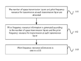
- Step 101 allocating the number of space transmission layers and pilot frequency resource for transmission at each transmission layer.
- Step 102 generating pilot frequency resource information according to the number of space transmission layers and the pilot frequency resource for transmission at each transmission layer.
- the pilot frequency resource information includes: pilot frequency resource for transmission at a first space transmission layer among the allocated space transmission layers, and the number of space transmission layers.
- the pilot frequency resource information includes allocated pilot frequency resource for transmission at each space transmission layer.
- the pilot frequency resource information includes pilot frequency resource for transmission at a first space transmission layer among the allocated space transmission layers.
- the pilot frequency resource information in the embodiment of the present invention is not limited to the preceding, as long as the UE can determine, according to the pilot frequency resource information, the pilot frequency resource used by the UE.
- Step 103 sending the pilot frequency resource information to a UE.
- the pilot frequency resource information can be carried in data information for sending to the UE.
- the pilot frequency resource information may further include the current usage status of pilot frequency resources in the communication system.
- the current usage status of pilot frequency resources specifies the number of resource units currently used in the communication system. According to the total number of parts of pilot frequency resources in the communication system and the number of resource units included in each part of pilot frequency resource, the UE can obtain possible pilot frequency resource information of a matching UE, where the matching UE indicates the UE that uses the same time frequency resources.
- the channel estimation value of the matching UE can be estimated, so as to perform signal detection or interference suppression detection, thereby improving the signal detection performance, correctly obtaining resource units of transmission service data, and correctly obtaining service data from the resource units of the transmission service data.
- the pilot frequency resource information may include the usage status of the pilot frequency resource for transmission at each allocated space transmission layer.
- the usage status of the pilot frequency resource may be the code of the pilot frequency resource so that the UE can obtain, according to the code and received data information, the channel estimation value of the channel used by the UE, and further obtain service data according to the channel estimation value.
- step 101 is specifically: allocating to at least one UE the number of space transmission layers and pilot frequency resource for transmission at each space transmission layer.
- FIG. 2 is a schematic diagram of a time frequency resource block.
- the time frequency resources in the communication system are time frequency resource blocks as shown in FIG. 2 .
- the method for handling data sending provided in the embodiment of the present invention is described as follows.
- a sub frame includes two timeslots: timeslot 0 and timeslot 1 .
- Each timeslot includes seven orthogonal frequency division multiplexing (OFDM) symbols, including 12 ⁇ 7 resource elements (REs).
- OFDM orthogonal frequency division multiplexing
- REs resource elements
- the following method can be used to allocate pilot frequency resource: for a first RE 201 , code division multiple (CDM) is introduced to the time domain to provide four orthogonal pilot frequency resources.
- CDM code division multiple
- CDM is introduced in the time domain to provide four orthogonal pilot frequency resources.
- the usage status of pilot frequency resources that are allocated to the UE and are transmitted at the space transmission layers is to allocate the code of the pilot frequency resources to the UE.
- the communication system arranges the dedicated pilot frequency resources that support space multiplexing transmission as shown in FIG. 2 .
- p1, p2, p5 and p6 are used to identify the pilot frequency resources at a first, second, fifth, and sixth space multiplexing transmission layers.
- p3, p4, p7, and p8 are used to identify the pilot frequency resources at a third, fourth, seventh, and eight space multiplexing transmission layers.
- the preceding arrangement sequence of pilot frequency resources is used. If the number of space multiplexing layers is equal to or smaller than 4, the pilot frequency resources corresponding to p1 to p4 are selected in sequence according to the number of space multiplexing layers to provide a high transmission throughput.
- the matching UEs In MU-MIMO mode, however, the matching UEs have a certain space isolation degree. The transmitted signals have different directions in space.
- the eNodeB allocates to the first UE one space transmission layer and pilot frequency resource for transmission at the space transmission layer. That is, the number of space transmission layers is 1, and the pilot frequency resource for transmission at the space transmission layer is p1.
- the eNodeB allocates to the second UE two space transmission layers and allocates to the second UE pilot frequency resource for transmission at each space transmission layer of the two allocated space transmission layers. That is, the number of space transmission layers is 2, and the pilot frequency resource for transmission at a first space transmission layer is p3.
- the communication system currently uses 24 REs.
- the eNodeB generates pilot frequency resource information according to the number of space transmission layers and pilot frequency resource for transmission at each space transmission layer allocated to the first UE and the current usage status of the pilot frequency resources in the communication system, and sends the pilot frequency resource information carried in data information to the first UE.
- the eNodeB generates pilot frequency resource information according to the number of space transmission layers and pilot frequency resource for transmission at each space transmission layer allocated to the second UE and the current usage status of the pilot frequency resources in the communication system, and sends the pilot frequency resource information carried in data information to the second UE.
- the first UE After obtaining pilot frequency resource information from the data information, the first UE learns that the number of space transmission layers allocated to itself is 1, that the pilot frequency resource for transmission at the first space multiplexing transmission layer is p1, and therefore learns that its own pilot frequency resource is p1. Further, the communication system currently uses 24 REs, that is, uses up the first RE 201 and second RE 202 , it can be learned that the data transmission resource unit is an RE other than the first RE 201 and second RE 202 as shown in FIG. 2 . Therefore, the first UE can correctly obtain from the data transmission resource unit the service data sent by the eNodeB.
- the second UE learns that the number of space transmission layers allocated to itself is 2, that the pilot frequency resource for transmission at the first space multiplexing transmission layer is p3, and therefore learns that its own pilot frequency resources are p3 and p4. Further, the communication system currently uses 24 REs, that is, uses up the first RE 201 and second RE 202 , it can be learned that the data transmission resource unit is an RE other than the first RE 201 and second RE 202 as shown in FIG. 2 . Therefore, the second UE can correctly obtain from the data transmission resource unit the service data sent by the eNodeB.
- the communication system can use only the same RE, for example, only the first RE 201 or second RE 202 , or can also use both REs. Therefore, in MU-MIMO working mode, the eNodeB and UE may agree on the current usage status of pilot frequency resources or the eNodeB may notify the UE of the current usage status of pilot frequency resources.
- Multiple matching UEs have a certain space isolation degree. Therefore, when the number of matching UEs is equal to or smaller than 4, the maximum number of transmission layers of each UE is equal to or smaller than 2, and the total number of transmission layers of multiple matching UEs is equal to or smaller than 4, the communication system may consider which type of the RE can be only used by the multiple matching UEs. In this way, when notifying the UEs of the current usage status of pilot frequency resources, the eNodeB does not need to send the types of REs in use, thereby reducing the information transmission volume, and simplifying processing of UEs on the information.
- the current usage status of pilot frequency resources in the communication system does not need to be carried in the pilot frequency resource information.
- the number of space transmission layers allocated by the eNodeB to the first UE 1 is 1, and the pilot frequency resource for transmission at the first space multiplexing transmission layer is p1.
- the number of space transmission layers allocated by the eNodeB to the second UE 2 is 2, and the pilot frequency resource for transmission at the first space multiplexing transmission layer is p2.
- the eNodeB generates pilot frequency resource information according to the number of space transmission layers and pilot frequency resource for transmission at each space transmission layer allocated to the first UE, and sends the pilot frequency resource information carried in the data information to the first UE.
- the eNodeB generates pilot frequency resource information according to the number of space transmission layers and pilot frequency resource for transmission at each space transmission layer allocated to the second UE, and sends the pilot frequency resource information carried in the data information to the second UE.
- the first UE learns that the number of space transmission layers allocated to itself is 1, that the pilot frequency resource for transmission at the first space multiplexing transmission layer is p1, and therefore learns that its own pilot frequency resource is p1.
- the second UE After obtaining the pilot frequency resource information from the data information, the second UE learns that the number of space transmission layers allocated to itself is 2, that the pilot frequency resource for transmission at the first space multiplexing transmission layer is p2, and therefore learns that its own pilot frequency resources are p2 and p5. Further, the communication system agrees on using the first RE 201 in advance, it can be learned that the data transmission resource unit is an RE other than the first RE 201 as shown in FIG. 2 . Therefore, the first and second UEs can correctly obtain respectively from the data transmission resource unit the service data sent by the eNodeB.
- the UE can obtain the pilot frequency resource information of other matching UEs through the current usage status of the pilot frequency resources in the communication system, for example, by agreeing on the RE or REs used by the matching UEs. For example, if the eNodeB and UE agrees on using the first RE 201 in advance, in the preceding embodiment, the first UE learns that its own pilot frequency resource is p1, and infers that the pilot frequency resources used by the second UE may be p2, p5, and p6.
- the first UE can estimate the channel estimation value of the second UE by detecting pilot frequency resources p2, p5, and p6, and perform signal detection or interface suppression detection according to the channel estimation value of the second UE.
- the second UE learns that its own pilot frequency resources are p2 and p5, and infers that the pilot frequency resources used by the first UE may be p1 and p6. In this way, the second UE can estimate the channel estimation value of the first UE by detecting pilot frequency resources p1 and p6, and perform signal detection or interface suppression detection according to the channel estimation value of the first UE.
- FIG. 3 is a schematic diagram of another time frequency resource block. Compared with the time frequency resource block in FIG. 2 , in the time frequency resource block shown in FIG. 3 , a first RE 201 , second RE 202 , third RE 203 , and fourth RE 204 respectively correspond to pilot frequency resources at a first, second, third, and fourth space multiplexing transmission layers, which are marked by p1, p2, p3, and p4.
- the eNodeB allocates to the first UE one space transmission layer and pilot frequency resource for transmission at the space transmission layer. That is, the number of space transmission layers is 1, and the pilot frequency resource for transmission at the space transmission layer is p1.
- the eNodeB allocates to the second UE two space transmission layers and allocates to the second UE pilot frequency resource for transmission at each space transmission layer of the two allocated space transmission layers. That is, the number of space transmission layers is 2, and the pilot frequency resource for transmission at the first space transmission layer is p2.
- the pilot frequency resources currently used by the communication system are p1, p2, and p3.
- the eNodeB generates pilot frequency resource information according to the number of space transmission layers and pilot frequency resource for transmission at each space transmission layer allocated to the first UE and the current usage status of the pilot frequency resources in the communication system, and sends the pilot frequency resource information carried in data information to the first UE.
- the eNodeB generates pilot frequency resource information according to the number of space transmission layers and pilot frequency resource for transmission at each space transmission layer allocated to the second UE and the current usage status of the pilot frequency resources in the communication system, and sends the pilot frequency resource information carried in data information to the second UE.
- the first UE After the first UE obtains the pilot frequency resource information from the data information, according to the pilot frequency resource information, the first UE learns that the number of space transmission layers allocated to itself is 1, that the pilot frequency resource for transmission at the first space multiplexing transmission layer is p1, and therefore learns that its own pilot frequency resource is p1. Further, since the pilot frequency resources currently used by the communication system are p1, p2, and p3, it can be learned that the data transmission resource unit is an RE other than the first RE 201 , second RE 202 , and third RE 203 as shown in FIG. 3 . Therefore, the first UE can correctly obtain from the data transmission resource unit the service data sent by the eNodeB.
- the first UE learns that its own pilot frequency resource is p1, and infers that the pilot frequency resources used by the second UE may be p2 and p3. In this way, the first UE can estimate the channel estimation value of the second UE by detecting pilot frequency resources p2 and p3, and perform signal detection or interface suppression detection according to the channel estimation value of the second UE.
- the second UE learns that the number of space transmission layers allocated to itself is 2, that the pilot frequency resource for transmission at the first space multiplexing transmission layer is p2, and therefore learns that its own pilot frequency resources are p2 and p3. Further, since the pilot frequency resources currently used by the communication system are p1, p2, and p3, it can learned that the data transmission resource unit is an RE other than the first RE 201 , second RE 202 , and third RE 203 as shown in FIG. 3 . Therefore, the second UE can correctly obtain from the data transmission resource unit the service data sent by the eNodeB.
- the second UE learns that its own pilot frequency resources are p2 and p3, and infers that the pilot frequency resource used by the first UE may be p1. In this way, the second UE can estimate the channel estimation value of the first UE by detecting pilot frequency resource p1, and perform signal detection or interface suppression detection according to the channel estimation value of the first UE.
- FIG. 4 is a flowchart of a method for handling data receiving provided in an embodiment of the present invention.
- the embodiment can be implemented by a UE. As shown in FIG. 4 , the method includes:
- Step 301 receiving pilot frequency resource information
- Step 302 determining pilot frequency resource according to the pilot frequency resource information
- the pilot frequency resource information in step 301 can include received pilot frequency resource for transmission at a first space transmission layer among space transmission layers and the number of space transmission layers allocated to the UE. Accordingly, in step 302 , according to the pilot frequency resource for transmission at the first space transmission layer and the number of space transmission layers, the UE can obtain its own pilot frequency resource. Or, the pilot frequency resource information in step 301 can be the received pilot frequency resource for transmission at each space transmission layer. In this case, in step 302 , the pilot frequency resource of the UE can be directly obtained according to the pilot frequency resource information. In addition, the pilot frequency resource information in step 301 can be the received pilot frequency resource for transmission at the first space transmission layer among the space transmission layers. In this way, when the number of space transmission layers is preset for each UE, the UE can obtain its own pilot frequency resource according to the preset number of its own space transmission layers and pilot frequency resource for transmission at the first space transmission layer;
- Step 303 obtaining, according to the received data information and pilot frequency resource, a channel estimation value of a channel used by the UE;
- the mapping relationship between the pilot frequency resource and a code can be preset. Accordingly, in step 303 , the code corresponding to the determined pilot frequency resource of the UE can be obtained according to the mapping relationship between the pilot frequency resource and the code, thereby obtaining the channel estimation value of the channel used by the UE.
- the code of the pilot frequency resource may also be sent by the eNodeB;
- the first half section of c1 is [+1 +1]
- the first half section of c2 is [+1 ⁇ 1], and they are orthogonal.
- the second half section of c1 is [+1 +1]
- the second half section of c2 is [+1 ⁇ 1], and they are also orthogonal.
- c1 and c2 are orthogonal. That is, c1 and c2 are vectors that are orthogonal by section.
- c3 and c4 are vectors that are orthogonal by section.
- c1 and c2 are also vectors that are orthogonal by section.
- c3 and c4 are vectors that are also orthogonal by section.
- the code of the pilot frequency resource can select other 4 ⁇ 4 orthogonal matrix that has the section-by-section orthogonal feature. According to related regulations of the 3GPP, by using 4 ⁇ 4 orthogonal matrix that has the section-by-section orthogonal feature can improve the channel estimation performance.
- Step 304 obtaining service data from the data information according to the received data information and channel estimation value.
- the pilot frequency resource information received at step 301 further includes the current usage status of the pilot frequency resource in the communication system. Accordingly, the UE can estimate the channel estimation value of another UE except itself among the matching UEs according to the current usage status of pilot frequency resources, and perform signal detection or interference suppression detection according to the channel estimation value of another UE.
- FIG. 5 is a flowchart of a method for handling data receiving provided in another embodiment of the present invention.
- the procedures of the embodiment may be implemented by a first UE. As shown in FIG. 5 , the embodiment includes the following steps:
- Step 401 receiving, by a UE, data information, where the data information includes pilot frequency resource information of the UE and current usage status of pilot frequency resources in a communication system, and the pilot frequency resource information of the UE includes pilot frequency resource for transmission at a first space transmission layer among space transmission layers and the number of space transmission layers allocated to the UE.
- Step 402 determining, by the UE, pilot frequency resource of the UE according to the pilot frequency resource for transmission at the first space transmission layer and the number of space transmission layers.
- Step 403 obtaining, by the UE, a code corresponding to the pilot frequency resource of the UE according to a preset mapping relationship between the pilot frequency resource and the code.
- Step 404 obtaining, by the UE, a channel estimation value of a channel used by the UE, according to the received data information and obtained code of the pilot frequency resource; and estimating a channel estimation value of another UE or interfering UE except itself among matching UEs according to the current usage status of pilot frequency resources in the communication system.
- the time frequency resource in the communication system is the time frequency resource block as shown in FIG. 2 .
- the following method can be used to obtain the channel estimation value of the channel used by the UE.
- the receive signal on one receive antenna of the UE is as follows:
- ⁇ tilde over (h) ⁇ 1 to ⁇ tilde over (h) ⁇ 8 are synthesized channel coefficients
- pilot frequency resource at the first space transmission layer at the transmit end, it may be the eNodeB that performs the following processing:
- s indicates the pilot frequency symbol transmitted on the pilot frequency resource
- a first column is on the first RE 201 of a sixth OFDM symbol in timeslot 0 , and is transmitted over eight transmit antennas respectively.
- a second column is on the first RE 201 of a seventh OFDM symbol in timeslot 0 , and is transmitted over eight transmit antennas respectively.
- a third column is on the first RE 201 of a sixth OFDM symbol in timeslot 1 , and is transmitted over eight transmit antennas respectively.
- a fourth column is on the first RE 201 of a seventh OFDM symbol in timeslot 1 , and is transmitted over eight transmit antennas respectively. Accordingly, for the pilot frequency resources at space transmission layers 1 to 4 , codes c 1 to c 4 are used respectively. Similarly, the pilot frequency resources at space transmission layers 5 to 8 may be transmitted on the second RE 202 by using the same method.
- the corresponding receive signal in the four first RE 201 areas is as follows:
- n indicates the noise
- ⁇ tilde over (h) ⁇ 1 to ⁇ tilde over (h) ⁇ 4 indicate respectively coefficients of four synthesized channels, that is:
- the channel estimation values of ⁇ tilde over (h) ⁇ 2 to ⁇ tilde over (h) ⁇ 4 can be obtained. Similar channel estimation methods can be used to obtain the channel estimation values of ⁇ tilde over (h) ⁇ 5 to ⁇ tilde over (h) ⁇ 8 for the 12 second RE 202 s in FIG. 2 .
- ⁇ indicates the service data obtained after UE performs detection
- G indicates the processing vector of the UE
- H 1 indicates the channel estimation value of this UE
- H i indicates the channel estimation value of another matching UE or interfering UE among matching UEs except the UE itself
- I N indicates the N-dimension unit matrix
- P n indicates the noise power
- FIG. 6 is a structure diagram of an apparatus for handling data sending provided in an embodiment of the present invention.
- the apparatus for handling data sending can serve as an eNodeB, or be set in an eNodeB to implement the procedures of the embodiment as shown in FIG. 1 .
- the apparatus for handling data sending provided in this embodiment includes an allocating module 501 , a generating module 502 , and a sending module 503 .
- the allocating module 501 is configured to allocate the number of space transmission layers and pilot frequency resource for transmission at each transmission layer allocated to the UE.
- the generating module 502 is configured to generate pilot frequency resource information according to the number of space transmission layers and the pilot frequency resource for transmission at each transmission layer allocated by the allocating module 501 .
- the pilot frequency resource information may include: pilot frequency resource for transmission at a first space transmission layer among space transmission layers and the number of space transmission layers allocated to the UE, or pilot frequency resource for transmission at each space transmission layer allocated to the UE, or pilot frequency resource for transmission at the first space transmission layer among the space transmission layers allocated to the UE.
- the pilot frequency resource information may further include: current usage status of pilot frequency resources in the communication system and/or usage status of pilot frequency resource for transmission at each space transmission layer allocated to the UE, for example, in CDM mode, the code of the pilot frequency resource for transmission at each space transmission layer allocated to the UE.
- the sending module 503 is configured to send to the UE the pilot frequency resource information generated by the generating module 502 .
- FIG. 7 is a structure diagram of an apparatus for handling data receiving provided in an embodiment of the present invention.
- the apparatus for handling data sending can serve as a UE, or be set in a UE to implement the procedures of the embodiment as shown in FIG. 4 or FIG. 5 .
- the apparatus for handling data sending provided in this embodiment includes a receiving module 601 , a pilot frequency resource obtaining module 602 , a first obtaining module 603 , and a second obtaining module 604 .
- the receiving module 601 is configured to receive data information and pilot frequency resource information.
- the pilot frequency obtaining module 602 is configured to determine pilot frequency resource of the UE according to the pilot frequency resource information received by the receiving module 601 .
- the first obtaining module 603 is configured to obtain a channel estimation value of a channel used by the UE, according to the data information received by the receiving module 601 and the pilot frequency resource obtained by the obtaining module 602 .
- the first obtaining module 603 may obtain, according to a preset mapping relationship between pilot frequency resource and a code, a code corresponding to the pilot frequency resource of the UE determined by the pilot frequency resource obtaining module 602 .
- the pilot frequency resource information carries the code of the pilot frequency resource
- the first obtaining module 603 obtains the code of the pilot frequency resource from the pilot frequency resource information, and further obtains the channel estimation value of the channel used by the UE, according to the data information received by the receiving module 601 and the code of the pilot frequency resource.
- the second obtaining module 604 is configured to perform data detection and obtain service data according to the data information received by the receiving module 601 and the channel estimation value obtained by the first obtaining module 603 .
- ⁇ indicates the service data obtained after UE performs detection
- G indicates the processing vector of the UE
- H 1 indicates the channel estimation value of the UE
- H i indicates the channel estimation value of another matching UE or interfering UE among matching UEs except the UE itself
- I N indicates the N-dimension unit matrix
- P n indicates the noise power
- the pilot frequency resource information may be specifically: the pilot frequency resource for transmission at a first space transmission layer among space transmission layers and the number of space transmission layers received by the receiving module 601 , or the pilot frequency resource for transmission at each space transmission layer received by the receiving module 601 .
- the pilot frequency resource information may also be the pilot frequency resource for transmission at the first space transmission layer among the space transmission layers received by the receiving module 601 . Accordingly, the pilot frequency resource obtaining module 602 determines the pilot frequency resource of the UE according to the preset number of space transmission layers and the pilot frequency resource for transmission at the first space transmission layer.
- FIG. 8 is a structure diagram of an apparatus for handling data receiving provided in another embodiment of the present invention.
- the apparatus for handling data sending can serve as a UE, or be set in a UE to implement the procedures of the embodiment as shown in FIG. 4 or FIG. 5 .
- the apparatus for handling data receiving in this embodiment includes a storing module 605 configured to store a preset mapping relationship between pilot frequency resource and a code. Accordingly, the first obtaining module 603 obtains, according to the mapping relationship between the pilot frequency resource and the code stored in the storing module 605 , the code of the pilot frequency resource determined by the pilot frequency resource obtaining module 602 .
- the receiving module 601 is configured to receive the code that is of the pilot frequency resource and is sent by the eNodeB.
- the code may be included in the pilot frequency resource information.
- the first obtaining module 603 obtains, according to the data information received by the receiving module 601 and the code that is of the pilot frequency resource and is sent by the eNodeB, the channel estimation value of the channel used by the UE.
- FIG. 9 is a structure diagram of an apparatus for handling data receiving provided in another embodiment of the present invention.
- the apparatus for handling data sending can serve as a UE, or be set in a UE to implement the procedures of the embodiment as shown in FIG. 4 or FIG. 5 .
- the data information received by the receiving module 601 further includes the current usage status of pilot frequency resources in the communication system.
- the apparatus for handling data receiving further includes a channel estimating module 606 and a processing module 607 .
- the channel estimating module 606 is configured to estimate the channel estimation value of another matching UE or interfering UE among the matching UEs except the UE itself according to the current usage status of pilot frequency resources in the communication system received by the receiving module 601 .
- the processing module 607 is configured to perform signal detection or interference suppression detection according to the channel estimation value of another matching UE or interfering UE among the matching UEs except the UE itself estimated by the channel estimating module 606 .
- a communication system is provided in an embodiment of the present invention.
- the communication system includes an eNodeB and a UE.
- the eNodeB is configured to allocate the number of space transmission layers and pilot frequency resource for transmission at each space transmission layer, generate pilot frequency resource information according to the number of space transmission layers and the pilot frequency resource for transmission at each space transmission layer, and send the pilot frequency resource information to the UE.
- the eNodeB can be implemented through the apparatus for handling data sending provided in the embodiment as shown in FIG. 6 .
- the UE is configured to receive the data information and pilot frequency resource information sent by the eNodeB, determine pilot frequency resource according to the pilot frequency resource information, obtain, according to the data information and the pilot frequency resource, the channel estimation value of the channel used by the UE, and obtain service data according to the data information and the channel estimation value.
- the UE can be implemented through the apparatus for handling data receiving provided in the embodiment as shown in FIG. 7 , FIG. 8 , or FIG. 9 .
- FIG. 10 is a structure diagram of a communication system provided in an embodiment of the present invention.
- the eNodeB uses the apparatus for handling data sending provided in the embodiment as shown in FIG. 6
- the UE uses the apparatus for handling data receiving provided in the embodiment as shown in FIG. 9 .
- the connection relationship between corresponding modules in the UE and eNodeB is the same as that in FIG. 10 .
- the program can be stored in a storage medium that can be read by a computer. When the program runs, the program executes the steps in the preceding method embodiments of the present invention.
- the storage medium can be ROM, RAM, disk, or CD that can store program codes.
- pilot frequency resource information is generated according to the number of space transmission layers and pilot frequency resource for transmission at each space transmission layer allocated to the UE, and is sent to the UE. Then, according to the pilot frequency resource information, the UE can determine the specifically used pilot frequency resource to effectively distinguish the specific user channels, obtain correct channel estimation values, improve the channel estimation performance, and obtain correct service data.
Landscapes
- Engineering & Computer Science (AREA)
- Signal Processing (AREA)
- Computer Networks & Wireless Communication (AREA)
- Mobile Radio Communication Systems (AREA)
Applications Claiming Priority (1)
| Application Number | Priority Date | Filing Date | Title |
|---|---|---|---|
| PCT/CN2009/071537 WO2010124456A1 (zh) | 2009-04-28 | 2009-04-28 | 数据发送处理方法与装置、数据接收处理方法与装置 |
Related Parent Applications (1)
| Application Number | Title | Priority Date | Filing Date |
|---|---|---|---|
| PCT/CN2009/071537 Continuation WO2010124456A1 (zh) | 2009-04-28 | 2009-04-28 | 数据发送处理方法与装置、数据接收处理方法与装置 |
Publications (2)
| Publication Number | Publication Date |
|---|---|
| US20120039297A1 US20120039297A1 (en) | 2012-02-16 |
| US8902809B2 true US8902809B2 (en) | 2014-12-02 |
Family
ID=43031678
Family Applications (1)
| Application Number | Title | Priority Date | Filing Date |
|---|---|---|---|
| US13/283,771 Active 2030-06-21 US8902809B2 (en) | 2009-04-28 | 2011-10-28 | Method and apparatus for handling data sending and receiving |
Country Status (4)
| Country | Link |
|---|---|
| US (1) | US8902809B2 (zh) |
| EP (1) | EP2413556A4 (zh) |
| CN (1) | CN102100045B (zh) |
| WO (1) | WO2010124456A1 (zh) |
Cited By (1)
| Publication number | Priority date | Publication date | Assignee | Title |
|---|---|---|---|---|
| US10181935B2 (en) | 2014-05-26 | 2019-01-15 | Huawei Technologies Co., Ltd. | Pilot configuration method and apparatus |
Families Citing this family (7)
| Publication number | Priority date | Publication date | Assignee | Title |
|---|---|---|---|---|
| CN101877689B (zh) | 2009-04-28 | 2012-10-17 | 华为技术有限公司 | 数据发送处理方法与装置、数据接收处理方法与装置 |
| CN102100045B (zh) | 2009-04-28 | 2014-12-10 | 华为技术有限公司 | 数据发送处理方法与装置、数据接收处理方法与装置 |
| US20130301563A1 (en) * | 2012-05-11 | 2013-11-14 | Samsung Electronics Co., Ltd | Pilot design for millimeter wave broadband |
| EP3151498B1 (en) | 2014-06-26 | 2019-11-20 | Huawei Technologies Co. Ltd. | Fbmc-based pilot sending method, channel estimating method and related devices |
| CN106487446B (zh) * | 2016-06-23 | 2018-08-14 | 兰州理工大学 | 适合于强度调制/直接检测式的光空时网格码编码方法 |
| JP2024049871A (ja) * | 2022-09-29 | 2024-04-10 | 株式会社Kddi総合研究所 | 無線通信におけるチャネル推定を高度化する端末装置、制御方法、及びプログラム |
| JP2024049870A (ja) * | 2022-09-29 | 2024-04-10 | 株式会社Kddi総合研究所 | 無線通信におけるチャネル推定を高度化する基地局装置、制御方法、及びプログラム |
Citations (34)
| Publication number | Priority date | Publication date | Assignee | Title |
|---|---|---|---|---|
| CN1464667A (zh) | 2002-06-14 | 2003-12-31 | 华为技术有限公司 | 阵列收发系统中的参考信号发射接收方法及其应用 |
| CN1534897A (zh) | 2003-04-01 | 2004-10-06 | 华为技术有限公司 | Fdd系统中天线阵列对下行专用信道信号发射的方法及装置 |
| US20050180449A1 (en) | 2004-02-16 | 2005-08-18 | Ranta-Aho Karri | Method and computer program for controlling radio resources, user equipment, radio network controller, and base station |
| CN1842176A (zh) | 2005-03-30 | 2006-10-04 | 华为技术有限公司 | 一种基于ip接入的ip用户实现移动数据业务的方法 |
| CN1889554A (zh) | 2005-06-27 | 2007-01-03 | 华为技术有限公司 | 导频传送方法 |
| US20070147536A1 (en) * | 2005-12-27 | 2007-06-28 | Ezer Melzer | Wireless communication device employing interference-sensitive mode selection and associated methods |
| WO2007098456A2 (en) | 2006-02-21 | 2007-08-30 | Qualcomm Incorporated | Spatial pilot structure for multi-antenna wireless communication |
| US7298805B2 (en) * | 2003-11-21 | 2007-11-20 | Qualcomm Incorporated | Multi-antenna transmission for spatial division multiple access |
| USRE40254E1 (en) | 1999-03-03 | 2008-04-22 | Nokia Corporation | Method and system for realising a fast control channel in a cellular radio network |
| WO2008061045A2 (en) | 2006-11-10 | 2008-05-22 | Qualcomm Incorporated | Providing antenna diversity in a wireless communication system |
| CN101227249A (zh) | 2007-01-16 | 2008-07-23 | 中兴通讯股份有限公司 | 一种信道编码和空时编码级联发射方法 |
| CN101242214A (zh) | 2002-10-25 | 2008-08-13 | 高通股份有限公司 | Mimo通信系统的导频 |
| WO2008103317A2 (en) | 2007-02-16 | 2008-08-28 | Interdigital Technology Corporation | Precoded pilot transmission for multi-user and single user mimo communications |
| US20080212701A1 (en) | 2007-02-16 | 2008-09-04 | Interdigital Technology Corporation | Method and apparatus for transmitting control signaling for mimo transmission |
| US20080285488A1 (en) * | 2002-10-25 | 2008-11-20 | Qualcomm Incorporated | Mimo wlan system |
| CN101370240A (zh) | 2007-08-15 | 2009-02-18 | 上海贝尔阿尔卡特股份有限公司 | 多用户mimo通信系统中基于用户反馈的调度方法和装置 |
| WO2009026768A1 (en) | 2007-08-31 | 2009-03-05 | Fujitsu Limited | Wireless communication system and wireless communication method |
| US20090215399A1 (en) * | 2008-02-22 | 2009-08-27 | Nokia Corporation | Signal processing in electronic apparatus |
| US20100085866A1 (en) * | 2006-12-31 | 2010-04-08 | Posdata Co., Ltd. | Apparatus and method for estimating channel in mimo system based ofdm/ofdma |
| US20100272032A1 (en) * | 2009-04-28 | 2010-10-28 | Motorola, Inc. | Method of signaling particular types of resource elements in a wireless communication system |
| US7826489B2 (en) | 2007-03-23 | 2010-11-02 | Qualcomm Incorporated | Method and apparatus for improved estimation of selective channels in an OFDMA system with dedicated pilot tones |
| WO2010124456A1 (zh) | 2009-04-28 | 2010-11-04 | 华为技术有限公司 | 数据发送处理方法与装置、数据接收处理方法与装置 |
| US20110019605A1 (en) | 2008-03-21 | 2011-01-27 | Nortel Networks Limited | Multimedia broadcast multicast service (mbms) utilizing spatial multiplexing |
| US7889758B2 (en) * | 2004-08-27 | 2011-02-15 | Tsinghua University | Method for allocating subchannel in wireless network |
| US20120044902A1 (en) * | 2009-04-28 | 2012-02-23 | Sun Weijun | Method and apparatus for processing data sending, and method and apparatus for processing data receiving |
| US8165018B2 (en) * | 2006-03-17 | 2012-04-24 | Rockstar Bidco, LP | Closed-loop MIMO systems and methods |
| US8243678B2 (en) * | 2008-03-10 | 2012-08-14 | Motorola Mobility, Inc. | Hierarchical pilot structure in wireless communication systems |
| US20120269295A9 (en) * | 2007-03-12 | 2012-10-25 | Hyun Soo Ko | Method for transmitting control information in multiple antenna system |
| US8363633B2 (en) * | 2007-12-16 | 2013-01-29 | Lg Electronics Inc. | Method of transmitting data in multiple antenna system |
| US20130044727A1 (en) | 2011-08-15 | 2013-02-21 | Motorola Mobility Llc | Method and apparatus for control channel transmission and reception |
| US8488694B2 (en) * | 2008-05-06 | 2013-07-16 | Industrial Technology Research Institute | System and method for pilot design |
| US8593976B2 (en) * | 2005-01-26 | 2013-11-26 | Panasonic Corporation | Wireless base station and terminal equipment |
| US8619620B2 (en) * | 2008-09-16 | 2013-12-31 | Qualcomm Incorporated | Methods and systems for transmission mode selection in a multi channel communication system |
| US8665811B2 (en) * | 2011-08-15 | 2014-03-04 | Motorola Mobility Llc | Reference signal for a control channel in wireless communication network |
-
2009
- 2009-04-28 CN CN200980124741.8A patent/CN102100045B/zh active Active
- 2009-04-28 WO PCT/CN2009/071537 patent/WO2010124456A1/zh active Application Filing
- 2009-04-28 EP EP09843868A patent/EP2413556A4/en not_active Ceased
-
2011
- 2011-10-28 US US13/283,771 patent/US8902809B2/en active Active
Patent Citations (36)
| Publication number | Priority date | Publication date | Assignee | Title |
|---|---|---|---|---|
| USRE40254E1 (en) | 1999-03-03 | 2008-04-22 | Nokia Corporation | Method and system for realising a fast control channel in a cellular radio network |
| CN1464667A (zh) | 2002-06-14 | 2003-12-31 | 华为技术有限公司 | 阵列收发系统中的参考信号发射接收方法及其应用 |
| CN101242214A (zh) | 2002-10-25 | 2008-08-13 | 高通股份有限公司 | Mimo通信系统的导频 |
| US8320301B2 (en) * | 2002-10-25 | 2012-11-27 | Qualcomm Incorporated | MIMO WLAN system |
| US20080285488A1 (en) * | 2002-10-25 | 2008-11-20 | Qualcomm Incorporated | Mimo wlan system |
| CN1534897A (zh) | 2003-04-01 | 2004-10-06 | 华为技术有限公司 | Fdd系统中天线阵列对下行专用信道信号发射的方法及装置 |
| US7298805B2 (en) * | 2003-11-21 | 2007-11-20 | Qualcomm Incorporated | Multi-antenna transmission for spatial division multiple access |
| US20050180449A1 (en) | 2004-02-16 | 2005-08-18 | Ranta-Aho Karri | Method and computer program for controlling radio resources, user equipment, radio network controller, and base station |
| US7889758B2 (en) * | 2004-08-27 | 2011-02-15 | Tsinghua University | Method for allocating subchannel in wireless network |
| US8593976B2 (en) * | 2005-01-26 | 2013-11-26 | Panasonic Corporation | Wireless base station and terminal equipment |
| CN1842176A (zh) | 2005-03-30 | 2006-10-04 | 华为技术有限公司 | 一种基于ip接入的ip用户实现移动数据业务的方法 |
| CN1889554A (zh) | 2005-06-27 | 2007-01-03 | 华为技术有限公司 | 导频传送方法 |
| US20070147536A1 (en) * | 2005-12-27 | 2007-06-28 | Ezer Melzer | Wireless communication device employing interference-sensitive mode selection and associated methods |
| WO2007098456A2 (en) | 2006-02-21 | 2007-08-30 | Qualcomm Incorporated | Spatial pilot structure for multi-antenna wireless communication |
| US8165018B2 (en) * | 2006-03-17 | 2012-04-24 | Rockstar Bidco, LP | Closed-loop MIMO systems and methods |
| WO2008061045A2 (en) | 2006-11-10 | 2008-05-22 | Qualcomm Incorporated | Providing antenna diversity in a wireless communication system |
| US20100085866A1 (en) * | 2006-12-31 | 2010-04-08 | Posdata Co., Ltd. | Apparatus and method for estimating channel in mimo system based ofdm/ofdma |
| CN101227249A (zh) | 2007-01-16 | 2008-07-23 | 中兴通讯股份有限公司 | 一种信道编码和空时编码级联发射方法 |
| US20080212702A1 (en) | 2007-02-16 | 2008-09-04 | Interdigital Technology Corporation | Precoded pilot transmission for multi-user and single user mimo communications |
| US20080212701A1 (en) | 2007-02-16 | 2008-09-04 | Interdigital Technology Corporation | Method and apparatus for transmitting control signaling for mimo transmission |
| WO2008103317A2 (en) | 2007-02-16 | 2008-08-28 | Interdigital Technology Corporation | Precoded pilot transmission for multi-user and single user mimo communications |
| US20120269295A9 (en) * | 2007-03-12 | 2012-10-25 | Hyun Soo Ko | Method for transmitting control information in multiple antenna system |
| US7826489B2 (en) | 2007-03-23 | 2010-11-02 | Qualcomm Incorporated | Method and apparatus for improved estimation of selective channels in an OFDMA system with dedicated pilot tones |
| CN101370240A (zh) | 2007-08-15 | 2009-02-18 | 上海贝尔阿尔卡特股份有限公司 | 多用户mimo通信系统中基于用户反馈的调度方法和装置 |
| WO2009026768A1 (en) | 2007-08-31 | 2009-03-05 | Fujitsu Limited | Wireless communication system and wireless communication method |
| US8363633B2 (en) * | 2007-12-16 | 2013-01-29 | Lg Electronics Inc. | Method of transmitting data in multiple antenna system |
| US20090215399A1 (en) * | 2008-02-22 | 2009-08-27 | Nokia Corporation | Signal processing in electronic apparatus |
| US8243678B2 (en) * | 2008-03-10 | 2012-08-14 | Motorola Mobility, Inc. | Hierarchical pilot structure in wireless communication systems |
| US20110019605A1 (en) | 2008-03-21 | 2011-01-27 | Nortel Networks Limited | Multimedia broadcast multicast service (mbms) utilizing spatial multiplexing |
| US8488694B2 (en) * | 2008-05-06 | 2013-07-16 | Industrial Technology Research Institute | System and method for pilot design |
| US8619620B2 (en) * | 2008-09-16 | 2013-12-31 | Qualcomm Incorporated | Methods and systems for transmission mode selection in a multi channel communication system |
| US20120044902A1 (en) * | 2009-04-28 | 2012-02-23 | Sun Weijun | Method and apparatus for processing data sending, and method and apparatus for processing data receiving |
| WO2010124456A1 (zh) | 2009-04-28 | 2010-11-04 | 华为技术有限公司 | 数据发送处理方法与装置、数据接收处理方法与装置 |
| US20100272032A1 (en) * | 2009-04-28 | 2010-10-28 | Motorola, Inc. | Method of signaling particular types of resource elements in a wireless communication system |
| US20130044727A1 (en) | 2011-08-15 | 2013-02-21 | Motorola Mobility Llc | Method and apparatus for control channel transmission and reception |
| US8665811B2 (en) * | 2011-08-15 | 2014-03-04 | Motorola Mobility Llc | Reference signal for a control channel in wireless communication network |
Non-Patent Citations (21)
| Title |
|---|
| Alcatel-Lucent et al., "Support Multi-layer Beamforming in LTE", 3GPP TSG RAN WG1 #56, Mar. 2009, pp. 1-3. |
| Chinese Office Action mailed Feb. 25, 2013 for corresponding Chinese Application No. 200980124741.8. |
| Control signaling aspects of MU-MIMO, 3GPP TSG RAN WG1 Meeting #50, Athens, Greece, Aug. 25-29, 2007. |
| Extended European Search Report dated Jun. 6, 2012 issued in corresponding European Patent Application No. 10769270.9. |
| Extended European Search Report dated Mar. 19, 2012 issued in corresponding European Patent Application No. 09843868.2. |
| Final Office Action issued on Jun. 12, 2014 in copending U.S. Appl. No. 13/282,971. |
| First Chinese Office Action issued Jul. 13, 2012 in corresponding Chinese Patent Application No. 200980124741.8. |
| Freescale Semiconductor Inc., "Reference signalling for MU-MIMO", 3GPP TSG RAN WG1 #49, May 2007, pp. 1-4. |
| International Search Report for PCT/CN2009/071537, mailed Feb. 4, 2010. |
| International Search Report mailed Jul. 29, 2010 issued in corresponding International Patent Application No. PCT/CN2010/072030. |
| Motorola, "Control Signaling for Enhanced DL Transmission for LTE Discussion and Decision", 3GPP TSG RAN WG1 #56, Mar. 2009, pp. 1-10. |
| Nokia et al., "UE-specific reference symbol multiplexing for LTE-Advanced downlink", 3GPP TSG RAN WG1 Meeting #56, Mar. 2009, pp. 1-8. |
| Nokia Siemens Networks, "LTE Multiuser MIMO and Interference Suppression in the UE", TSG RAN WG1 Meeting #49, Jun. 2007, pp. 1-3. |
| Notice of Allowance issued in copending U.S. Appl. No. 13/282,971 on Sep. 29, 2014. |
| Office Action issued on Feb. 28, 2014 in copending U.S. Appl. No. 13/282,971. |
| Philips, "Performance of LTE DL MU-MIMO with dedicated pilots", 3GPP TSG RAN WG1, Meeting #48, Mar. 2007, pp. 1-5. |
| Qualcomm Europe, "Overview of DL Spatial Multiplexing Schemes for E-UTRA", 3GPP TSG-RAN WG1 #44, Feb. 2005, pp. 1-5. |
| Research in Motion et al., "Further Discussion on Signaling of DM-RS Port for LTE-A MIMO Transmission", 3GPP TSG RAN WG1 Meeting #59, Nov. 2009, pp. 1-6. |
| Written Opinion of International Searching Authority dated Feb. 4, 2010, Issued in Application No. PCT/CN2009/071537. |
| Written Opinion of the International Searching Authority mailed Jul. 29, 2010 issued in corresponding International Patent Application No. PCT/CN2010/072030. |
| Yong Sun et al., "Proposed Text of MIMO for the IEEE 802.16m Amendment", IEEE 802.16 Broadband Wireless Access Working Group, Mar. 2009, pp. 1-36. |
Cited By (1)
| Publication number | Priority date | Publication date | Assignee | Title |
|---|---|---|---|---|
| US10181935B2 (en) | 2014-05-26 | 2019-01-15 | Huawei Technologies Co., Ltd. | Pilot configuration method and apparatus |
Also Published As
| Publication number | Publication date |
|---|---|
| WO2010124456A1 (zh) | 2010-11-04 |
| US20120039297A1 (en) | 2012-02-16 |
| CN102100045A (zh) | 2011-06-15 |
| EP2413556A1 (en) | 2012-02-01 |
| EP2413556A4 (en) | 2012-04-18 |
| CN102100045B (zh) | 2014-12-10 |
Similar Documents
| Publication | Publication Date | Title |
|---|---|---|
| US8902809B2 (en) | Method and apparatus for handling data sending and receiving | |
| US8902848B2 (en) | Method and apparatus for processing data sending, and method and apparatus for processing data receiving | |
| USRE48954E1 (en) | Method for indicating a DM-RS antenna port in a wireless communication system | |
| CN110212958B (zh) | 一种移动通信系统中的信道信息反馈方法和装置 | |
| US9860900B2 (en) | Method for indicating a DM-RS antenna port in a wireless communication system | |
| RU2527930C2 (ru) | Способ и устройство предварительного кодирования на основе опорных сигналов демодуляции смешанного мультиплексирования | |
| RU2548028C1 (ru) | Способ и устройство для преобразования ресурсов и мультиплексирования с кодовым разделением каналов | |
| KR101726864B1 (ko) | 무선랜 시스템에서 mu-mimo 방법, mu-mimo를 위한 액세스 포인트 및 스테이션 | |
| EP3681054A1 (en) | Multi-antenna transmission method, terminal and base station | |
| EP2637340B1 (en) | Method and device for feeding back downlink channel feedback information, and method and device for user matching | |
| US20110134859A1 (en) | Frame transmission method using precoding for supporting mu-mimo, and base station supporting the frame transmission method | |
| CN103222201A (zh) | 用于发送和接收码本子集限制位图的方法和设备 | |
| US9615280B2 (en) | Calculating and reporting channel characteristics | |
| US8611447B1 (en) | Feedback and user scheduling for multi-user multiple input multiple output (MU-MIMO) system | |
| KR20130048249A (ko) | 비적응성 재전송을 위한 방법 및 장치 | |
| CN106105121B (zh) | 用于在大规模mimo系统中获取下行数据的方法与设备 | |
| CN102439931B (zh) | 数据发送处理方法与装置、数据接收处理方法与装置 | |
| CN112703683A (zh) | 用于mimo系统中的处理的方法、装置和计算机软件产品 | |
| Zhang et al. | A joint detection algorithm for PUCCH |
Legal Events
| Date | Code | Title | Description |
|---|---|---|---|
| AS | Assignment |
Owner name: HUAWEI TECHNOLOGIES CO., LTD., CHINA Free format text: ASSIGNMENT OF ASSIGNORS INTEREST;ASSIGNORS:SUN, WEIJIN;QU, BINGYU;LI, YAND;AND OTHERS;SIGNING DATES FROM 20111021 TO 20111027;REEL/FRAME:027280/0436 |
|
| STCF | Information on status: patent grant |
Free format text: PATENTED CASE |
|
| CC | Certificate of correction | ||
| MAFP | Maintenance fee payment |
Free format text: PAYMENT OF MAINTENANCE FEE, 4TH YEAR, LARGE ENTITY (ORIGINAL EVENT CODE: M1551) Year of fee payment: 4 |
|
| MAFP | Maintenance fee payment |
Free format text: PAYMENT OF MAINTENANCE FEE, 8TH YEAR, LARGE ENTITY (ORIGINAL EVENT CODE: M1552); ENTITY STATUS OF PATENT OWNER: LARGE ENTITY Year of fee payment: 8 |