US8902808B2 - Interference mitigation with scheduling and dynamic power spectrum allocation for wireless networks - Google Patents
Interference mitigation with scheduling and dynamic power spectrum allocation for wireless networks Download PDFInfo
- Publication number
- US8902808B2 US8902808B2 US13/463,478 US201213463478A US8902808B2 US 8902808 B2 US8902808 B2 US 8902808B2 US 201213463478 A US201213463478 A US 201213463478A US 8902808 B2 US8902808 B2 US 8902808B2
- Authority
- US
- United States
- Prior art keywords
- tone
- hub
- power
- sinr
- rbm
- Prior art date
- Legal status (The legal status is an assumption and is not a legal conclusion. Google has not performed a legal analysis and makes no representation as to the accuracy of the status listed.)
- Active, expires
Links
- 230000000116 mitigating effect Effects 0.000 title claims abstract description 23
- 238000001228 spectrum Methods 0.000 title abstract description 28
- 238000000034 method Methods 0.000 claims abstract description 168
- 230000005540 biological transmission Effects 0.000 claims description 22
- 239000011159 matrix material Substances 0.000 claims description 15
- 230000003595 spectral effect Effects 0.000 claims description 13
- 238000005457 optimization Methods 0.000 claims description 9
- 230000004044 response Effects 0.000 claims description 7
- 230000007774 longterm Effects 0.000 claims description 3
- 238000012935 Averaging Methods 0.000 claims description 2
- 230000014509 gene expression Effects 0.000 claims description 2
- 238000005259 measurement Methods 0.000 abstract description 16
- 230000006978 adaptation Effects 0.000 abstract description 15
- 238000013468 resource allocation Methods 0.000 abstract description 8
- 230000003044 adaptive effect Effects 0.000 abstract description 7
- 238000007726 management method Methods 0.000 abstract description 2
- 238000004088 simulation Methods 0.000 description 10
- 230000008901 benefit Effects 0.000 description 5
- 238000013461 design Methods 0.000 description 4
- 238000005562 fading Methods 0.000 description 4
- 230000001413 cellular effect Effects 0.000 description 3
- 238000005516 engineering process Methods 0.000 description 3
- 230000006872 improvement Effects 0.000 description 3
- 238000012545 processing Methods 0.000 description 3
- 238000013459 approach Methods 0.000 description 2
- 238000004891 communication Methods 0.000 description 2
- 238000004590 computer program Methods 0.000 description 2
- 230000007423 decrease Effects 0.000 description 2
- 238000011161 development Methods 0.000 description 2
- 238000010586 diagram Methods 0.000 description 2
- 238000011156 evaluation Methods 0.000 description 2
- 230000002349 favourable effect Effects 0.000 description 2
- 230000009286 beneficial effect Effects 0.000 description 1
- 238000004364 calculation method Methods 0.000 description 1
- 230000008859 change Effects 0.000 description 1
- 230000000593 degrading effect Effects 0.000 description 1
- 230000000694 effects Effects 0.000 description 1
- 230000000763 evoking effect Effects 0.000 description 1
- 239000013307 optical fiber Substances 0.000 description 1
- 230000000737 periodic effect Effects 0.000 description 1
- 238000012827 research and development Methods 0.000 description 1
- 230000007480 spreading Effects 0.000 description 1
Images


Classifications
-
- H—ELECTRICITY
- H04—ELECTRIC COMMUNICATION TECHNIQUE
- H04W—WIRELESS COMMUNICATION NETWORKS
- H04W52/00—Power management, e.g. Transmission Power Control [TPC] or power classes
- H04W52/04—Transmission power control [TPC]
- H04W52/18—TPC being performed according to specific parameters
- H04W52/24—TPC being performed according to specific parameters using SIR [Signal to Interference Ratio] or other wireless path parameters
- H04W52/243—TPC being performed according to specific parameters using SIR [Signal to Interference Ratio] or other wireless path parameters taking into account interferences
-
- H—ELECTRICITY
- H04—ELECTRIC COMMUNICATION TECHNIQUE
- H04L—TRANSMISSION OF DIGITAL INFORMATION, e.g. TELEGRAPHIC COMMUNICATION
- H04L5/00—Arrangements affording multiple use of the transmission path
- H04L5/003—Arrangements for allocating sub-channels of the transmission path
- H04L5/0058—Allocation criteria
- H04L5/0073—Allocation arrangements that take into account other cell interferences
-
- H—ELECTRICITY
- H04—ELECTRIC COMMUNICATION TECHNIQUE
- H04L—TRANSMISSION OF DIGITAL INFORMATION, e.g. TELEGRAPHIC COMMUNICATION
- H04L5/00—Arrangements affording multiple use of the transmission path
- H04L5/003—Arrangements for allocating sub-channels of the transmission path
- H04L5/0058—Allocation criteria
- H04L5/0075—Allocation using proportional fairness
-
- H—ELECTRICITY
- H04—ELECTRIC COMMUNICATION TECHNIQUE
- H04W—WIRELESS COMMUNICATION NETWORKS
- H04W52/00—Power management, e.g. Transmission Power Control [TPC] or power classes
- H04W52/04—Transmission power control [TPC]
- H04W52/18—TPC being performed according to specific parameters
- H04W52/24—TPC being performed according to specific parameters using SIR [Signal to Interference Ratio] or other wireless path parameters
- H04W52/241—TPC being performed according to specific parameters using SIR [Signal to Interference Ratio] or other wireless path parameters taking into account channel quality metrics, e.g. SIR, SNR, CIR or Eb/lo
-
- H—ELECTRICITY
- H04—ELECTRIC COMMUNICATION TECHNIQUE
- H04W—WIRELESS COMMUNICATION NETWORKS
- H04W52/00—Power management, e.g. Transmission Power Control [TPC] or power classes
- H04W52/04—Transmission power control [TPC]
- H04W52/06—TPC algorithms
- H04W52/14—Separate analysis of uplink or downlink
- H04W52/143—Downlink power control
-
- H—ELECTRICITY
- H04—ELECTRIC COMMUNICATION TECHNIQUE
- H04W—WIRELESS COMMUNICATION NETWORKS
- H04W52/00—Power management, e.g. Transmission Power Control [TPC] or power classes
- H04W52/04—Transmission power control [TPC]
- H04W52/06—TPC algorithms
- H04W52/14—Separate analysis of uplink or downlink
- H04W52/146—Uplink power control
Definitions
- This invention relates to wireless cellular networks, wireless backhaul for high capacity data networks, and to systems and methods for mitigating interference. It is especially applicable to practical power spectrum adaptation techniques for Non Line of Sight (NLOS) wireless backhaul products in MicroCell and PicoCell networks, as well as fixed wireless access.
- NLOS Non Line of Sight
- Interference is a major bottleneck in wireless systems design.
- the performance of each user or link in a wireless network depends not only on its own transmission, but also on the interference coming from other links or users' transmissions.
- traditional technologies service multiple users within each cell by distributing them over orthogonal dimensions, e.g. in different time slots as in Time Division Multiple Access (TDMA) systems, or over different frequency bands as in Frequency Division Multiple Access (FDMA) systems, or by spreading them across time and frequency as in Code Division Multiple Access (CDMA) systems.
- TDMA Time Division Multiple Access
- FDMA Frequency Division Multiple Access
- CDMA Code Division Multiple Access
- Kwon et al. proposes a power adaptation method based on Newton's method (NM), is particularly relevant to this problem.
- the method described in Kwon et al. shows a significant gain compared to the most straightforward method of transmitting at the maximum allowable power for all transmitters across all tones.
- the method in Kwon et al. is, however, both computationally complex, and relatively slow in convergence, albeit being faster than previously proposed methods.
- NLOS backhaul technology provides a cost-effective wireless NLOS method to increase the cell site capacity of PicoCell and MicroCell deployments.
- a cellular network may comprise several PicoCells, each covering a relatively small area, as a means to increase the network capacity for areas with dense data traffic.
- the users within each PicoCell are served by their own PicoCell base-station, also called access modules (AM).
- AM access modules
- the AMs are collocated with the remote backhaul modules (RBM).
- RBM remote backhaul modules
- Each RBM is connected to some central base-stations, also known as the hubs, via wireless backhauls links which are meant to replace the expensive optical fiber links.
- the hubs are responsible for the transmission strategies and radio resource management for the different RBMs.
- the backhaul architecture assumes that the wireless backhauls links and the access links operate at different frequencies. From a backhaul design perspective, the interest is therefore mitigating the interhub interference, thereby maximizing the aggregate data capacity of the RBMs.
- NLOS backhaul technology has been an area of considerable research and development activity of late.
- the above referenced copending PCT application and US patent application claiming priority from U.S. provisional application No. 61/382,217 disclose a method for measuring the co-channel interference in a NLOS environment, and for scheduling resources based on measured co-channel interference data.
- This method is referred to herein as managed adaptive resource allocation (MARA).
- the methods disclosed in Beaudin comprise measuring data indicative of interference, e.g. the channel gain, between each hub and each RBM Unit, periodically during active service.
- the corresponding measurements can be thought of, or represented, as a channel matrix whose entries describe the frequency domain channel gains between each hub and each RBM of the interference environment.
- MARA matrix This matrix of measurements, e.g. frequency domain channel gains will be referred to herein as a MARA matrix.
- the MARA matrix is used, for example, to intelligently group each RBM to its most favorable hub, as well as to allocate resource blocks in such a way as to reduce interference between links and optimize aggregate capacity of the network, so as to organize the network resources in an optimal configuration.
- An object of the present invention is to provide improved or alternative methods for interference mitigation, with scheduling and power allocation, which may be particularly applicable for NLOS wireless backhaul networks.
- the present invention seeks to provide improvements to, or mitigate disadvantages of, these known systems and methods, or at least provide an alternative.
- aspects of the present invention provide methods, systems, apparatuses and software products for interference mitigation, with scheduling and power allocation, based on iterative operations with reduced computational complexity and/or faster convergence.
- a first aspect of the invention provides a method for mitigating interference in a wireless network comprising a plurality of nodes, each comprising a transmitter and a receiver, comprising the steps of:
- the iterative operation comprises, based on an initial power level or a power level of a previous iteration, and for an objective function based on scheduling assignments for each node at all tones or tone sets, iteratively optimizing a weighted sum-rate across all nodes.
- the frequency domain channel gains comprise per tone channel gains, and the method may comprise updating and allocating power on a tone by tone basis at each iteration.
- Tones may comprise sets of tones S ⁇ ⁇ 1, . . . , N ⁇ where N is the number of tones of the OFDMA multiplexing scheme, and said frequency domain channel gains may comprise per tone set channel gains to allow for allocating power at each iteration on a tone-set by tone-set basis.
- updating of the power levels may comprise adjusting the transmit powers in the downlink and/or the uplink.
- nodes of the wireless network comprise hubs of a wireless backhaul network, each hub serving a plurality of RBMs.
- embodiments of the present invention may work with any scheduling policy
- preferred embodiments specifically adopt a proportional fairness objective across the RBMs.
- the disclosed methods then work as follows. For a specific set of channel gains between all hubs and RBMs, and fixed RBM scheduling (over time and frequency), the power spectral density level of every hub at each frequency tone, is adjusted according to practically feasible methods.
- Equation 2 When the system performance is limited by interhub interference only, assuming an overall proportional fairness objective across the RBMs, an appropriate objective function can be defined and solved, which depends on the scheduling policy and power spectrum allocation of the different hubs across all tones. For a fixed scheduling policy, the problem becomes a weighted sum-rate optimization as defined in Equation 2.
- IFEM iterative function evaluation method
- Theta-IFEM determine the appropriate power spectral density level of every hub at every frequency tone iteratively, for every specific RBM scheduling.
- Methods are based on suitable Signal-to-Interference-plus-Noise Ratio (SINR) approximation, with an objective of maximizing the network overall utility.
- SINR Signal-to-Interference-plus-Noise Ratio
- the power of the lth hub at the nth tone may be calculated iteratively using Equation 3.
- Theta-IFEM In a method according to a second embodiment, called Theta-IFEM, the high SINR approximation of IFEM is corrected by a factor Theta ( ⁇ ) that corresponds to the maximum power transmission, as set out in Equation 5.
- IFEM and Theta-IFEM show faster convergence and lower computational complexity compared to previously developed methods, which makes them amenable to practical implementation. They can also be implemented in a distributed fashion, and asynchronously at each hub. IFEM and Theta-IFEM show a significant performance gain as compared to fixed power transmission strategy, used by the majority of traditional networks.
- Full-IFEM and modified-IFEM have similar performance as the methods proposed in Kwon et al., but with lower computational complexity.
- the entries in a MARA matrix as described in Beaudin may represent the frequency domain channel average gains between all hubs and RBMs in the backhaul wireless network. Due to the fixed deployment of hubs and RBMs, and the existence of the line of sight between each hub and its own RBMs, the frequency domain channel of the backhaul network is relatively flat.
- the MARA matrix entries thus comprise a good representation of the actual network channel gains, and are used to develop methods according to alternative embodiments.
- a method according to a fifth embodiment uses Equation 4, where the per-tone channel gains used for IFEM, are replaced by the frequency domain average channel gains.
- methods according to sixth, seventh and eighth embodiments are based on Theta-IFEM, Full-IFEM and MIFEM, but, similarly, use the frequency domain average channel gain, and respectively are called MARA IFEM, MARA Theta-IFEM, MARA Full-IFEM, and MARA MIFEM.
- Methods according to another aspect of the present invention are based on novel forms of Newton's method (NM), and in particular, the power spectrum adaptation step comprises a high SINR approximation of Newton's method as presented in Kwon et al.
- This novel Newton's method called high SINR Newton's method (HSNM)
- HSNM high SINR Newton's method
- MARA matrix MARA matrix
- every hub allocates the same power across one set of tones, rather than on a per-tone basis.
- This power allocation strategy suits the PHY specifications of several platforms.
- These tone-set implementations may be based on MARA IFEM, MARA Theta-IFEM, MARA Full-IFEM, MARA MIFEM, MARA Newton's method (MARA NM), or MARA HSNM.
- MARA IFEM MARA Theta-IFEM
- MARA Full-IFEM MARA MIFEM
- MARA MIFEM MARA Newton's method
- MARA HSNM MARA HSNM
- Each apparatus comprises processing means to find the power allocation of every hub at every tone, and/or alternatively at every set of tones.
- Each apparatus is evoked dynamically with any change in the channel information or scheduling policy, to determine the appropriate power spectral density levels.
- aspects of the invention further provide computer program products to implement the methods mentioned above, in systems or apparatuses intended to mitigate interference in wireless systems, via scheduling and adaptive power spectrum adaptation, and particularly for use in NLOS backhaul wireless networks.
- FIG. 1 shows a system model of a simple NLOS wireless backhaul network comprising one hub and 4 remote backhaul modules (RBMs), where every RBM is collocated with an access module (AM);
- RBMs remote backhaul modules
- AM access module
- FIG. 2 shows a schematic diagram of one NLOS wireless backhaul interference network comprising seven hubs and 4 remote backhaul modules (RBMs) per hub; it also labels, by way of example only, one scenario of interhub interference;
- RBMs remote backhaul modules
- FIG. 3 shows a table that summarizes the system parameters of the NLOS wireless backhaul network used to evaluate the performance of the invented methods
- FIG. 4 shows simulations schematic that plots the total sum rate across all hubs for different realizations of the channel, and using different methods of power spectrum adaptation; the hub-to-hub distance is set to 0.5 km, and hub-to-RBM distance is set to 0.15 km;
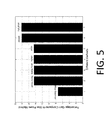
- FIG. 5 shows a bar chart which summarizes the percentage gain of the suggested methods, for different channel realizations; the hub-to-hub distance is set to 0.5 km, and hub-to-RBM distance is set to 0.15 km;
- FIG. 6 is a table showing the simulated performance of the individual and total rates for the different hubs, using both IFEM and MARA IFEM; the hub-to-hub distance is set to 0.5 km, and hub-to-RBM distance is set to 0.2 km;
- FIG. 7 shows the frequency domain gain of one particular channel of the central hub; the hub-to-hub distance is set to 0.5 km, and hub-to-RBM distance is set to 0.2 km;
- FIG. 8 shows the power spectrum allocation over the first 50 tones for both IFEM and MARA IFEM; the hub-to-hub distance is set to 0.5 km, and hub-to-RBM distance is set to 0.2 km;
- FIG. 9 shows a schematic of simulations that plots the total sum-rate for different realizations, versus various values of the same constant power allocation across all hubs; the hub-to-hub distance is set to 0.5 km, and hub-to-RBM distance is set to 0.15 km;
- FIG. 10 is a table showing the simulated performance of various proposed methods, for different values of hub-to-hub distance d; the hub-to-RBM distance is set to 0.15 km;
- FIG. 11 is a table showing the simulated performance of various proposed methods, for both cell-edge and cell-center RBMs; the hub-to-hub distance is set to 0.5 km;
- FIG. 12 is a table showing the simulated performance of various proposed methods, for both cell-edge and cell-center RBMs; the hub-to-hub distance is set to 1 km;
- FIG. 13 plots the total sum-rate versus the number of iterations to show the convergence speed of the proposed methods for high SINR regime
- FIG. 14 plots the total sum-rate versus the number of iterations to show the convergence speed of the proposed methods for low SINR regime
- FIG. 15 plots the total sum-rate versus the number of iterations to compare the convergence speed of Full-IFEM and MIFEM under different regimes.
- FIG. 16 is a schematic that plots the total sum-rate percentage gain for different tones set size, i.e. the set that shares the same power across its tones.
- IFEM IFEM
- MIFEM modified IFEM
- MARA based methods are called MARA IFEM, MARA Theta IFEM, MARA Full IFEM.
- Average Powers (AP) variants of these embodiments are also described.
- NM Newton's method
- MARA NM High SINR NM
- HSNM High SINR NM
- MARA HSNM MARA HSNM
- FIG. 1 represents a simple model of a simple NLOS wireless backhaul network comprising one hub and 4 remote backhaul modules (RBMs), where every RBM is co-located with an access module (AM) that supports the users in its PicoCell.
- RBMs remote backhaul modules
- AM access module
- FIG. 1 represents a simple model of a simple NLOS wireless backhaul network comprising one hub and 4 remote backhaul modules (RBMs), where every RBM is co-located with an access module (AM) that supports the users in its PicoCell.
- A access module
- the performance of wireless networks is typically limited by intercell interference. Unlike traditional networks which manage interference with specific frequency reuse patterns, methods according to preferred embodiments mitigate interference via dynamic power spectrum optimization, given that the scarcity of the available bandwidth continuously pushes modern networks towards a unity frequency reuse.
- the proposed methods and systems relate particularly to the NLOS wireless backhaul network comprising several hubs, each connected to, or serving, its own RBMs via wireless backhaul links. RBMs belonging to one hub are separated from each other using orthogonal frequency division multiple access (OFDMA) over a fixed bandwidth, where only one RBM is active at each frequency tone.
- OFDMA orthogonal frequency division multiple access
- FIG. 2 shows a schematic diagram representing a NLOS wireless backhaul interference network comprising seven hubs, and 4 remote backhaul modules (RBMs) per hub.
- RBMs remote backhaul modules
- RBMs belonging to one hub are separated from each other using orthogonal frequency division multiple access (OFDMA) over a fixed bandwidth, where only one RBM is active at each frequency tone.
- OFDMA orthogonal frequency division multiple access
- N be the total number of subcarriers.
- k be the scheduled RBM of the lth hub at the nth tone
- h n jlk be the channel response between hub j and the kth RBM of the lth hub at the nth tone
- h n jlk be the average channel response between hub j and the kth RBM of the lth hub.
- n D,l be the power allocated for the lth hub at the nth tone
- SINR n D,l be the signal-to-interference-plus-noise ratio at the scheduled RBM of the lth hub at the nth tone
- S D max be the peak power constraint imposed on each hub at every tone. While any appropriate scheduling policy may be used, preferred embodiments of the present invention are described comprising mitigating interhub interference by solving an overall proportional fairness objective across the RBMs:
- the objective function depends on both the scheduling policy and the power spectrum allocation of the different hubs across all tones.
- embodiments of the current invention provide novel and practical power spectrum adaptation methods to increase the weighted sum-rate across all the hubs, as the problem becomes the following weighted sum-rate optimization:
- the weights w D,lk and the power levels are updated with the channel condition and RBM scheduling changes, so as to dynamically adapt with the interference environment.
- the weight w D,lk is set as the inverse of the long term average rate R D,lk .
- IFEM calculates the power of the lth hub at the nth tone using the following iterative equation:
- P D , l n ⁇ ( t + 1 ) [ w D , lk ⁇ j ⁇ l ⁇ w D , jk ′ ⁇ ⁇ h ljk ′ n ⁇ 2 ⁇ 2 + ⁇ i ⁇ j ⁇ P D , i n ⁇ ( t ) ⁇ ⁇ h ijk ′ n ⁇ 2 ] 0 S D max Equation ⁇ ⁇ 3 ( IFEM ) where k is the scheduled RBM of the lth hub at the nth tone, and k′ is the scheduled RBM of the jth hub at the nth tone.
- MARA IFEM calculates the power of the lth hub at the nth tone using the following iterative equation:
- MARA IFEM the per-tone channel gains are replaced by the frequency domain average channel gains used for IFEM.
- IFEM and MARA IFEM can achieve a throughput improvement of up to 14% as compared to traditional networks with maximum power transmission. Both IFEM and MARA IFEM are computationally feasible, and fast in convergence. They can be implemented in a distributed fashion, and asynchronously at each hub.
- MARA-IFEM With respect to MARA-IFEM, as disclosed in Beaudin, methods are provided for measuring the channel gain between each hub and each RBM Unit, periodically during active service.
- the corresponding measurements can be represented as a channel matrix whose entries describe the frequency domain channel gains between each hub and each RBM of the interference environment.
- the MARA matrix is used in Beaudin, for example, to intelligently group each RBM to its most favorable hub, as well as to allocate resource blocks in such a way as to reduce interference between links and optimize aggregate capacity of the network, so as to organize the network in an optimal configuration.
- the MARA channel measurements in Beaudin can be done on a per-tone basis, for every hub-RBM pair. They are subsequently provided to either a central server for further centralized processing, or to each of the several hubs for distributed processing.
- the MARA measurements can alternatively provide the frequency domain average channel gains.
- the MARA measurements used in the text denote the frequency domain average channel gains.
- SON Self-Organizing Network
- Theta-IFEM corrects the high SINR approximation of IFEM (Equation 3) by including a factor Theta that corresponds to the maximum power transmission. It calculates the power of the lth hub at the nth tone using the following iterative equation:
- ⁇ jl n SINR D , j n 1 + SINR D , j n SINR D , l n 1 + SINR D , l n is calculated based on the maximum power transmission.
- a method according to a fourth embodiment, MARA Theta-IFEM calculates the power in a similar way to Theta-IFEM, where the per-tone channel gains are replaced by the frequency domain average channel gain.
- Full-IFEM calculates the power of the lth hub at the nth tone using the following iterative equation:
- P D , l n ⁇ ( t + 1 ) [ w D , lk ⁇ SINR D , l n ⁇ ( t ) 1 + SINR D , l n ⁇ ( t ) ⁇ j ⁇ l ⁇ w D , jk ′ ⁇ ⁇ h ljk ′ n ⁇ 2 ⁇ 2 + ⁇ i ⁇ j ⁇ P D , i n ⁇ ( t ) ⁇ ⁇ h ijk ′ n ⁇ 2 ⁇ SINR D , j n ⁇ ( t ) 1 + SINR D , j n ⁇ ( t ) ] 0 S D max Equation ⁇ ⁇ 6 ( Full ⁇ - ⁇ IFEM )
- MIFEM calculates the power of the lth hub at the nth tone using the following iterative equation:
- P D , l n ⁇ ( t + 1 ) [ w D , lk ⁇ j ⁇ l ⁇ t D , jl n ⁇ ( t ) - P D , l n ⁇ ( t ) SINR D , l n ⁇ ( t ) ] 0 S D max Equation ⁇ ⁇ 7 ( MIFEM )
- Equation 6 for Full-IFEM, accounts more fully for SINR at each iteration.
- simplifications were then sought to Full-IFEM, to reduce computational complexity and/or to provide faster convergence during iteration.
- Equation 7 provides a different way of writing the gradient.
- Theta IFEM provides a further approximation that accounts for SINR even more simply through the Theta term, calculated based on the maximum power transmission.
- Equation 3 for IFEM provides even further simplification of Full IFEM, because, for a high SINR approximation, the SINR terms of Equation 6 (Full IFEM) may be further reduced.
- IFEM and related embodiments described above can offer significant advantages
- certain features of IFEM and MARA IFEM methods can also beneficially be adapted or applied to provide novel Newton's methods with advantages over the conventional systems with maximum power transmission.
- embodiments based on Newton's method are called MARA Newton's method (MARA NM), high SINR Newton's method (HSNM), and MARA high SINR Newton's method (MARA HSNM).
- MARA NM finds the power in a similar way to Newton's method (NM) in Kwon et al., where the per-tone channel gains are replaced by the frequency domain average channel gain.
- HSNM calculates the power of the lth hub at the nth tone using the following iterative equation:
- MARA high SINR Newton's method (MARA HSNM) calculates the power of the lth hub at the nth tone using the following iterative equation:
- MARA NM The performances of MARA NM, HSNM and MARA HSNM are similar to Full-IFEM, IFEM and MARA IFEM, respectively. They show, however, higher computational complexity, and slower convergence at high SINR level simulations.
- FIG. 3 shows a table that summarizes the system parameters of the simulated network, e.g. as shown in FIG. 2 . It comprises 7 hubs, with 4 RBMs per hub, with maximal frequency reuse, and 1024 subcarriers.
- the channel parameters correspond to a typical WIMAX deployment.
- FIG. 4 shows, schematically, results of simulations that plot the total sum rate across all hubs for different channel realizations (i.e., different shadowing scenarios).
- the hub-to-hub distance is set to 0.5 km
- hub-to-RBM distance is set to 0.15 km.
- the plot shows the performance comparison of the proposed methods according to each of the embodiments described above.
- Full-IFEM, MIFEM, MARA Full-IFEM and MARA MIFEM show the best performance, followed by IFEM, HSNM, MARA IFEM and MARA HSNM.
- a method according to yet another embodiment, called AP MARA IFEM found by taking the average values of the MARA IFEM powers on a per-hub basis, shows the next best performance, and it is still superior to the conventional maximum power transmission strategy.
- FIG. 5 shows a bar chart which summarizes the percentage gain of the simulated methods in FIG. 4 .
- Full-IFEM and MIFEM gain is approximately 18% compared to the maximum power transmission strategy.
- IFEM and HSNM show an approximate gain of 14% compared to the maximum power transmission strategy.
- FIG. 6 is a table showing the simulated performance of the individual and total rates for the different hubs, using both IFEM and MARA IFEM.
- the hub-to-hub distance is set to 0.5 km, and hub-to-RBM distance is set to 0.2 km.
- FIG. 7 shows the frequency domain response of one particular channel of the central hub.
- the hub-to-hub distance is set to 0.5 km, and hub-to-RBM distance is set to 0.2 km.
- the plot shows the flat fading behavior of the channel. This is due to the fixed deployment of the hubs and RBMs, where the K-factor used in modeling the channel is typically large, due to the strong line of sight path between hubs and RBMs, as compared to the NLOS paths.
- FIG. 8 shows the power spectrum allocation over the first 50 tones for both IFEM and MARA IFEM.
- the hub-to-hub distance is set to 0.5 km, and hub-to-RBM distance is set to 0.2 km.
- the plot shows how close are the values that are allocated for each tone using both IFEM and MARA IFEM. This is due to the flat fading channel, which makes the per-tone channel gains quite close to the average values.
- FIG. 9 shows schematically simulations that plot the total sum-rate for different realizations, versus various values of the same constant power allocation across all hubs.
- the hub-to-hub distance is set to 0.5 km, and hub-to-RBM distance is set to 0.15 km.
- the plot shows that the best constant power allocation is the maximum allowable power.
- FIG. 10 is a table showing the simulated performance of various proposed methods, for different values of hub-to-hub distance d.
- the hub-to-RBM distance is set to 0.15 km.
- the table shows that for fixed hub-to-RBM distance, smaller cells have a higher MARA IFEM gain compared to the maximum power transmission. This is because interference is higher for smaller values of the hub-to-hub distance. Power Adaptation methods are therefore expected to offer higher gain.
- the table also shows how Full-IFEM and MARA IFEM performance is quite similar, especially for larger values of the hub-to-hub distance, where SINR is typically large.
- FIG. 11 is a table showing the simulated performance of various proposed methods, for both cell-edge and cell-center RBMs.
- the hub-to-hub distance is set to 0.5 km.
- the table shows that for fixed hub-to-hub distance, MARA IFEM gain compared to the maximum power transmission is larger at the cell-edge than it is at the cell-center, since interference is higher at the cell-edge.
- the table also shows the superiority of Full-IFEM at the cell-edge of small hub-to-hub distance, where the value of SINR is relatively low.
- FIG. 12 is a table showing the simulated performance of various proposed methods, for both cell-edge and cell-center RBMs.
- the hub-to-hub distance is set to 1 km.
- the table shows that for fixed hub-to-hub distance, MARA IFEM gain compared to the maximum power transmission is larger at the cell-edge than it is at the cell-center, since interference is higher at cell-edge.
- the table also shows Full-IFEM method and MARA IFEM performances are quite similar for large hub-to-hub distance, since the value of SINR is relatively large.
- FIG. 13 plots the total sum-rate versus the number of iterations to show the convergence speed of the proposed methods for high SINR regime. It shows how the proposed methods have a faster convergence compared to Newton's method.
- FIG. 14 plots the total sum-rate versus the number of iterations to show the convergence speed of the proposed methods for low SINR regime. It shows how the proposed methods have a fast convergence. Newton's method in this regime has the faster convergence. Its convergence, however, depends on choosing an appropriate step size, in addition to the higher computational complexity due to the Hessian terms calculations.
- FIG. 15 plots the total sum-rate versus the number of iterations to compare the convergence speed of MIFEM and Full-IFEM. It shows how MIFEM converges a bit faster at low level of SINR. At high level of SINR, MIFEM and Full-IFEM curves almost overlap.
- FIG. 16 is a schematic that plots the total sum-rate across for different tones set size, i.e. the set that shares the same power across its tones. For example, if the set size is 1, the sum-rate performance is at its best, since the power allocation is made on a per-tone basis. On the other hand, as the set size approaches its maximum value (i.e. the number of subcarriers), the performance decreases to reach the sum-rate corresponding to allocate the same power for every hub across all tones.
- AP MARA IFEM took the average values of the MARA IFEM powers on a per-hub basis. That is, methods wherein each hub allocates one power across all its tones by averaging the value of its power spectral density level, are envisaged.
- AP-IFEM AP MARA IFEM
- AP MARA IFEM AP Theta-IFEM
- AP MARA Theta-IFEM AP Full-IFEM
- AP MARA Full-IFEM AP MIFEM
- AP MARA MIFEM AP MARA NM
- AP HSNM AP MARA HSNM.
- methods according to embodiments may, for example, comprise performing the method steps for determining an optimum constant power allocation across all hubs.
- all weights w may be set to unity.
- methods may comprise dynamically adapting the power with any changes in any one or more of channel condition, traffic, and RBM scheduling, or for example by dynamically setting the weights according to the data traffic (e.g. the queue length).
- tones may be arranged as sets of tones S ⁇ ⁇ 1, . . . , N ⁇ where N is the number of tones of the OFDMA multiplexing scheme, in which case power may be allocated at each iteration on a tone-set by tone-set basis.
- P D , l n ⁇ ( t + 1 ) [ W D , lk ⁇ SINR D , l n ⁇ ( t ) 1 + SINR D , l n ⁇ ( t ) ⁇ ( 1 - ⁇ ⁇ ⁇ SINR D , l n ⁇ ( t ) ) ⁇ j ⁇ l ⁇ W D , jk ′ ⁇ ⁇ h ljk ′ n ⁇ 2 ⁇ SINR D , j n ⁇ ( t ) 1 + SINR D , j n ⁇ ( t ) ⁇ 2 + ⁇ i ⁇ j ⁇ P D , i n ⁇ ( t ) ⁇ ⁇ h ijk ′ n ⁇ 2 + ⁇ ⁇ ⁇ P D , j n ⁇ ( t ) ⁇ ⁇ h jjk ′ n ⁇ 2 ] 0 S D max
- SINR D , j n ⁇ ( t ) P D , j n ⁇ ( t ) ⁇ ⁇ h jjk ′ n ⁇ 2 ⁇ ( ⁇ 2 + ⁇ i ⁇ j ⁇ P D , i n ⁇ ( t ) ⁇ ⁇ h ijk ′ n ⁇ 2 + ⁇ ⁇ ⁇ P D , j n ⁇ ( t ) ⁇ ⁇ h jjk ′ n ⁇ 2 )
- ⁇ denotes the scale of the phase noise, used as a limit on the SINR level.
- Equations used for methods according to other embodiments described above may be similarly modified, where appropriate, by a factor ⁇ to account for phase noise.
- updating of power levels may comprise adjusting transmit power in the downlink and/or the uplink.
- Systems, methods, apparatuses, and software products according to embodiments of the present invention are particularly applicable to practical power spectrum adaptation techniques for Non Line of Sight (NLOS) wireless backhaul products in MicroCell and PicoCell networks, as well as Fixed Wireless Access Networks.
- NLOS Non Line of Sight
- the backhaul architecture assumes that the wireless backhaul links and the access links operate at different frequencies. From a backhaul design perspective, the interest is therefore mitigating the interhub interference, thereby maximizing the aggregate data capacity of the RBMs. The power spectrum adaptation of every hub thus becomes crucial to increase the system throughput.
- MARA IFEM frequency domain average channel gain
- MARA Theta-IFEM MARA Theta-IFEM
- Embodiments of the present invention also have application to future or next generation wireless networks, including access systems, where power spectrum adaptation methods are expected to play a major role in improving the systems performance, given the scarcity of the available radio resources.
- the disclosed methods and apparatuses provide practical solutions, with simple or reduced computational complexity and fast convergence.
- Theta-IFEM, IFEM, MARA Theta-IFEM, and MARA IFEM outperform traditional systems, and can be implemented in a distributed fashion, and asynchronously at each transmitter.
Landscapes
- Engineering & Computer Science (AREA)
- Signal Processing (AREA)
- Computer Networks & Wireless Communication (AREA)
- Quality & Reliability (AREA)
- Mobile Radio Communication Systems (AREA)
Abstract
Description
Where
-
R D,lk: long term average rate of the kth RBM of the lth hub. - RD,lk: instantaneous rate of the kth RBM of the lth hub.
- k=fD(l, n) assigns kth RBM of lth hub to nth tone.
where k is the scheduled RBM of the lth hub at the nth tone, and k′ is the scheduled RBM of the jth hub at the nth tone.
Where
is calculated based on the maximum power transmission.
where μ is the ascent direction step size, and ΔPn D,l is the updated Newton's direction.
where
Claims (31)
Priority Applications (2)
| Application Number | Priority Date | Filing Date | Title |
|---|---|---|---|
| US13/463,478 US8902808B2 (en) | 2011-05-06 | 2012-05-03 | Interference mitigation with scheduling and dynamic power spectrum allocation for wireless networks |
| US14/073,459 US9338753B2 (en) | 2011-05-06 | 2013-11-06 | Method and apparatus for performance management in wireless backhaul networks via power control |
Applications Claiming Priority (3)
| Application Number | Priority Date | Filing Date | Title |
|---|---|---|---|
| US201161483417P | 2011-05-06 | 2011-05-06 | |
| US201161506895P | 2011-07-12 | 2011-07-12 | |
| US13/463,478 US8902808B2 (en) | 2011-05-06 | 2012-05-03 | Interference mitigation with scheduling and dynamic power spectrum allocation for wireless networks |
Publications (2)
| Publication Number | Publication Date |
|---|---|
| US20120281648A1 US20120281648A1 (en) | 2012-11-08 |
| US8902808B2 true US8902808B2 (en) | 2014-12-02 |
Family
ID=47090197
Family Applications (1)
| Application Number | Title | Priority Date | Filing Date |
|---|---|---|---|
| US13/463,478 Active 2033-01-12 US8902808B2 (en) | 2011-05-06 | 2012-05-03 | Interference mitigation with scheduling and dynamic power spectrum allocation for wireless networks |
Country Status (1)
| Country | Link |
|---|---|
| US (1) | US8902808B2 (en) |
Cited By (1)
| Publication number | Priority date | Publication date | Assignee | Title |
|---|---|---|---|---|
| US10389499B2 (en) * | 2016-11-24 | 2019-08-20 | Fujitsu Limited | Method and apparatus for bit number allocation and power allocation of subcarriers and electronic equipment |
Families Citing this family (13)
| Publication number | Priority date | Publication date | Assignee | Title |
|---|---|---|---|---|
| CN102158867B (en) * | 2010-02-11 | 2013-04-17 | 华为技术有限公司 | Methods, devices and systems for scheduling cooperation resources and cooperation communication |
| US9332504B2 (en) | 2010-09-13 | 2016-05-03 | Blinq Wireless Inc. | System and method for self-optimized uplink power control in a fixed wireless backhaul network |
| US9544792B2 (en) | 2010-09-13 | 2017-01-10 | Blinq Wireless Inc. | System and method for joint scheduling in dual-carrier wireless backhaul networks |
| WO2013000068A1 (en) | 2011-06-30 | 2013-01-03 | Blinq Wireless Inc. | Method and apparatus for determining network clusters for wireless backhaul networks |
| US9338672B2 (en) | 2010-09-13 | 2016-05-10 | Blinq Wireless Inc. | System and method for coordinating hub-beam selection in fixed wireless backhaul networks |
| US9338753B2 (en) | 2011-05-06 | 2016-05-10 | Blinq Wireless Inc. | Method and apparatus for performance management in wireless backhaul networks via power control |
| US9237529B2 (en) | 2012-03-30 | 2016-01-12 | Blinq Wireless Inc. | Method and apparatus for managing interference in wireless backhaul networks through power control with a one-power-zone constraint |
| US9253740B2 (en) | 2012-11-29 | 2016-02-02 | Blinq Wireless Inc. | Method and apparatus for coordinated power-zone-assignment in wireless backhaul networks |
| EP3079426A4 (en) * | 2013-12-25 | 2017-03-08 | Huawei Technologies Co., Ltd. | Method and apparatus for allocating uplink resource, and macro base station |
| US10015788B2 (en) * | 2014-04-17 | 2018-07-03 | Blinq Wireless Inc. | System and method of signalling for point-to-multipoint (PtMP) transmission in fixed wireless backhaul networks |
| US10405192B2 (en) * | 2018-01-15 | 2019-09-03 | Charter Communications Operating, Llc | Methods and apparatus for allocation and reconciliation of quasi-licensed wireless spectrum across multiple entities |
| US10680769B2 (en) | 2018-10-01 | 2020-06-09 | Motorola Solutions, Inc. | Interference coordination in communication systems with dynamic spectrum management |
| CN112911600B (en) * | 2021-01-18 | 2023-10-24 | 长江大学 | An in-band full-duplex cognitive wireless network self-interference suppression method and device |
Citations (6)
| Publication number | Priority date | Publication date | Assignee | Title |
|---|---|---|---|---|
| US6441786B1 (en) * | 2001-07-20 | 2002-08-27 | Motorola, Inc. | Adaptive antenna array and method for control thereof |
| WO2008096383A1 (en) | 2007-02-09 | 2008-08-14 | Telecom Italia S.P.A. | Characterization of co-channel interference in a wireless communication system |
| US20080298486A1 (en) * | 2007-06-04 | 2008-12-04 | Nec Laboratories America, Inc. | Multi-cell interference mitigation via coordinated scheduling and power allocation in downlink odma networks |
| US20090221297A1 (en) * | 2003-11-06 | 2009-09-03 | Matsushita Electric Industrial Co.,Ltd. | Transmission Power Level Setting During Channel Assignment for Interference Balancing in a Cellular Wireless Communication System |
| US20100009748A1 (en) | 2008-07-14 | 2010-01-14 | David Keith Timperley | Gaming system and method of gaming |
| WO2011037319A1 (en) | 2009-09-28 | 2011-03-31 | Samsung Electronics Co., Ltd. | Method and device for user scheduling and managing transmit power in a communication system |
-
2012
- 2012-05-03 US US13/463,478 patent/US8902808B2/en active Active
Patent Citations (7)
| Publication number | Priority date | Publication date | Assignee | Title |
|---|---|---|---|---|
| US6441786B1 (en) * | 2001-07-20 | 2002-08-27 | Motorola, Inc. | Adaptive antenna array and method for control thereof |
| US20090221297A1 (en) * | 2003-11-06 | 2009-09-03 | Matsushita Electric Industrial Co.,Ltd. | Transmission Power Level Setting During Channel Assignment for Interference Balancing in a Cellular Wireless Communication System |
| WO2008096383A1 (en) | 2007-02-09 | 2008-08-14 | Telecom Italia S.P.A. | Characterization of co-channel interference in a wireless communication system |
| US20100159841A1 (en) | 2007-02-09 | 2010-06-24 | Sergio Barberis | Characterization of co-channel interference in a wireless communication system, in particular a cellular radio communication system |
| US20080298486A1 (en) * | 2007-06-04 | 2008-12-04 | Nec Laboratories America, Inc. | Multi-cell interference mitigation via coordinated scheduling and power allocation in downlink odma networks |
| US20100009748A1 (en) | 2008-07-14 | 2010-01-14 | David Keith Timperley | Gaming system and method of gaming |
| WO2011037319A1 (en) | 2009-09-28 | 2011-03-31 | Samsung Electronics Co., Ltd. | Method and device for user scheduling and managing transmit power in a communication system |
Non-Patent Citations (2)
| Title |
|---|
| Stolyar et al., entitled "Self-Organizing Dynamic Fractional Frequency Reuse for Best-Effort Traffic Through Distributed Inter-Cell Coordination," in INFOCOM, Apr. 2009. |
| Venturino et al., entitled "Coordinated Scheduling and Power Allocation in Downlink Multicell OFDMA Networks," IEEE Trans. Veh. Technol., vol. 6, No. 58, pp. 2835-2848, Jul. 2009. |
Cited By (1)
| Publication number | Priority date | Publication date | Assignee | Title |
|---|---|---|---|---|
| US10389499B2 (en) * | 2016-11-24 | 2019-08-20 | Fujitsu Limited | Method and apparatus for bit number allocation and power allocation of subcarriers and electronic equipment |
Also Published As
| Publication number | Publication date |
|---|---|
| US20120281648A1 (en) | 2012-11-08 |
Similar Documents
| Publication | Publication Date | Title |
|---|---|---|
| US8902808B2 (en) | Interference mitigation with scheduling and dynamic power spectrum allocation for wireless networks | |
| EP2115893B1 (en) | Mitigation of co-channel interference in a wireless communication system | |
| JP5744746B2 (en) | Method and apparatus for power allocation in a multi-carrier system | |
| US8676223B2 (en) | Backhaul communication for interference management | |
| US10055682B2 (en) | Self-optimizing deployment cascade control scheme and device based on TDMA for indoor small cell in interference environments | |
| KR101636382B1 (en) | Method and device for user schedulling and managing transmit power in hierarchical-cell or multi-cell communication system | |
| US8254947B2 (en) | Method of dimensioning radio access networks, corresponding system and computer program product | |
| US8335534B2 (en) | Distributed inter-cell interference mitigation in OFDMA multi-carrier wireless data networks | |
| US10080200B2 (en) | Intelligent deployment cascade control device based on an FDD-OFDMA indoor small cell in multi-user and interference environments | |
| US9338753B2 (en) | Method and apparatus for performance management in wireless backhaul networks via power control | |
| EP2011247B1 (en) | Power control in a wireless system having multiple interfering communication resources | |
| US9332504B2 (en) | System and method for self-optimized uplink power control in a fixed wireless backhaul network | |
| US9456360B2 (en) | Method and systems for decentralized interference management in a multi-antenna wireless communication system | |
| EP1944911A2 (en) | Reuse pattern network scheduling using load levels | |
| CN101925185B (en) | Interference suppression method of relay cellular network, base station and network system | |
| Rengarajan et al. | Self-organizing dynamic fractional frequency reuse on the uplink of OFDMA systems | |
| Gupta et al. | Resource allocation for self-backhauled networks with half-duplex small cells | |
| US9237529B2 (en) | Method and apparatus for managing interference in wireless backhaul networks through power control with a one-power-zone constraint | |
| Fawaz et al. | Queue-aware resource allocation in full-duplex multi-cellular wireless networks | |
| de Melo et al. | Power control with variable target SINR for D2D communications underlying cellular networks | |
| US9693357B2 (en) | Method and apparatus for allocating resource | |
| Huq et al. | A novel energy efficient packet-scheduling algorithm for CoMP | |
| CN103826231B (en) | Frequency multiplexing method and system in conjunction with Power Control | |
| Khorov et al. | Joint power control and time division to improve spectral efficiency in dense Wi-Fi networks | |
| de Melo et al. | Uplink power control with variable target SINR for D2D communications underlying cellular networks |
Legal Events
| Date | Code | Title | Description |
|---|---|---|---|
| AS | Assignment |
Owner name: BLINQ WIRELESS INC., CANADA Free format text: ASSIGNMENT OF ASSIGNORS INTEREST;ASSIGNORS:TANG, TAIWEN;BEAUDIN, STEVE ANDRE;SIGNING DATES FROM 20120424 TO 20120427;REEL/FRAME:028192/0759 Owner name: BLINQ WIRELESS INC., CANADA Free format text: ASSIGNMENT OF ASSIGNORS INTEREST;ASSIGNORS:DAHROUJ, HAYSSAM;YU, WEI;REEL/FRAME:028192/0722 Effective date: 20120503 |
|
| STCF | Information on status: patent grant |
Free format text: PATENTED CASE |
|
| MAFP | Maintenance fee payment |
Free format text: PAYMENT OF MAINTENANCE FEE, 4TH YR, SMALL ENTITY (ORIGINAL EVENT CODE: M2551) Year of fee payment: 4 |
|
| AS | Assignment |
Owner name: COMMUNICATION COMPONENTS ANTENNA INC., CANADA Free format text: AMALGAMATION;ASSIGNOR:BLINQ WIRELESS INC.;REEL/FRAME:052832/0090 Effective date: 20170101 |
|
| AS | Assignment |
Owner name: BLINQ NETWORKS INC., CANADA Free format text: ASSIGNMENT OF ASSIGNORS INTEREST;ASSIGNOR:COMMUNICATION COMPONENTS ANTENNA INC.;REEL/FRAME:053197/0075 Effective date: 20200710 |
|
| MAFP | Maintenance fee payment |
Free format text: PAYMENT OF MAINTENANCE FEE, 8TH YR, SMALL ENTITY (ORIGINAL EVENT CODE: M2552); ENTITY STATUS OF PATENT OWNER: SMALL ENTITY Year of fee payment: 8 |