US8899321B2 - Method of distributing a viscosity reducing solvent to a set of wells - Google Patents
Method of distributing a viscosity reducing solvent to a set of wells Download PDFInfo
- Publication number
- US8899321B2 US8899321B2 US13/084,256 US201113084256A US8899321B2 US 8899321 B2 US8899321 B2 US 8899321B2 US 201113084256 A US201113084256 A US 201113084256A US 8899321 B2 US8899321 B2 US 8899321B2
- Authority
- US
- United States
- Prior art keywords
- solvent
- wells
- well
- injection
- viscosity
- Prior art date
- Legal status (The legal status is an assumption and is not a legal conclusion. Google has not performed a legal analysis and makes no representation as to the accuracy of the status listed.)
- Active, expires
Links
Images


Classifications
-
- E—FIXED CONSTRUCTIONS
- E21—EARTH OR ROCK DRILLING; MINING
- E21B—EARTH OR ROCK DRILLING; OBTAINING OIL, GAS, WATER, SOLUBLE OR MELTABLE MATERIALS OR A SLURRY OF MINERALS FROM WELLS
- E21B43/00—Methods or apparatus for obtaining oil, gas, water, soluble or meltable materials or a slurry of minerals from wells
- E21B43/16—Enhanced recovery methods for obtaining hydrocarbons
-
- G—PHYSICS
- G06—COMPUTING OR CALCULATING; COUNTING
- G06Q—INFORMATION AND COMMUNICATION TECHNOLOGY [ICT] SPECIALLY ADAPTED FOR ADMINISTRATIVE, COMMERCIAL, FINANCIAL, MANAGERIAL OR SUPERVISORY PURPOSES; SYSTEMS OR METHODS SPECIALLY ADAPTED FOR ADMINISTRATIVE, COMMERCIAL, FINANCIAL, MANAGERIAL OR SUPERVISORY PURPOSES, NOT OTHERWISE PROVIDED FOR
- G06Q99/00—Subject matter not provided for in other groups of this subclass
Definitions
- the present invention relates generally to in situ hydrocarbon recovery including in situ viscous oil recovery. More particularly, the present invention relates to reducing pipeline capacity, surface solvent storage, or underground solvent storage costs in a solvent-dominated process for recovering in situ hydrocarbons.
- Solvent-dominated in situ oil recovery processes are those in which chemical solvents are used to reduce the viscosity of the in situ oil.
- a minority of commercial viscous oil recovery processes use solvents to reduce viscosity.
- Most commercial recovery schemes rely on thermal methods such as Cyclic Steam Stimulation (CSS, see, for example, U.S. Pat. No. 4,280,559) and Steam-Assisted Gravity Drainage (SAGD, see, for example U.S. Pat. No. 4,344,485) to reduce the viscosity of the in situ oil.
- CCS Cyclic Steam Stimulation
- SAGD Steam-Assisted Gravity Drainage
- thermal recovery technology practitioners have added chemical solvents, typically hydrocarbons, to the injected steam in order to obtain additional viscosity reduction.
- Examples include Liquid Addition to Steam For Enhancing Recovery (LASER, see, for example, U.S. Pat. No. 6,708,759) and Steam And Vapor Extraction processes (SAVEX, see, for example, U.S. Pat. No. 6,662,872). These processes use chemical solvents as an additive within an injection stream that is steam-dominated. Solvent-dominated recovery processes are a possible next step for viscous oil recovery technology. In these envisioned processes, chemical solvent is the principal component within the injected stream.
- Some non-commercial technology such as Vapor Extraction (VAPEX, see, for example, R. M. Butler & I. J. Mokrys, J. of Canadian Petroleum Technology, Vol. 30, pp. 97-106, 1991) and Cyclic Solvent-Dominated Recovery Process (CSDRP, see, for example, Canadian Patent No. 2,349,234) use injectants that may be 100%, or nearly all, chemical solvent.
- SDRPs solvent-dominated recovery processes
- CSDRP solvent-dominated recovery processes
- a CSDRP is typically, but not necessarily, a non-thermal recovery method that uses a solvent to mobilize viscous oil by cycles of injection and production.
- Solvent-dominated means that the injectant comprises greater than 50% by mass of solvent or that greater than 50% of the produced oil's viscosity reduction is obtained by chemical solvation rather than by thermal means.
- One possible laboratory method for roughly comparing the relative contribution of heat and dilution to the viscosity reduction obtained in a proposed oil recovery process is to compare the viscosity obtained by diluting an oil sample with a solvent to the viscosity reduction obtained by heating the sample.
- a CSDRP is predominantly a non-thermal process in that heat is not used principally to reduce the viscosity of the viscous oil, the use of heat is not excluded. Heating may be beneficial to improve performance, improve process start-up, or provide flow assurance during production. For start-up, low-level heating (for example, less than 100° C.) may be appropriate. Low-level heating of the solvent prior to injection may also be performed to provide general flow assurance such as preventing hydrate formation in tubulars and in the reservoir. Heating to higher temperatures may benefit recovery.
- a viscosity-reducing solvent is injected through a well into a subterranean viscous-oil reservoir, causing the pressure to increase.
- the pressure is lowered and reduced-viscosity oil is produced to the surface through the same well through which the solvent was injected.
- Multiple cycles of injection and production are used. In some instances, a well may not undergo cycles of injection and production, but only cycles of injection or only cycles of production.
- CSDRPs may be particularly attractive for thinner or lower-oil-saturation reservoirs.
- thermal methods utilizing heat to reduce viscous oil viscosity may be inefficient due to excessive heat loss to the overburden and/or underburden and/or reservoir with low oil content.
- the family of processes within the Lim et al. references describes embodiments of a particular SDRP that is also a cyclic solvent-dominated recovery process (CSDRP). These processes relate to the recovery of heavy oil and bitumen from subterranean reservoirs using cyclic injection of a solvent in the liquid state which vaporizes upon production.
- CSPTM technology The family of processes within the Lim et al. references may be referred to as CSPTM technology.
- the methodology should account for the fact that the scheduling of each well depends on the previous injection and production histories of the well, the injection and production rates of every other well in the field, the supply of solvent to the field, the value of each stream of components being injected and produced from that well, and the properties of the reservoir near the well and near the volume of the reservoir previously accessed by solvent.
- cyclic oil recovery processes also exist, such as cyclic steam stimulation (e.g., U.S. Pat. No. 3,739,852) and cyclic steam injection (e.g., U.S. Pat. No. 3,434,544), but the value of the produced injectant (water in these cases) is less than the value of solvent, and thus, careful management of the produced injectant is not as important. Moreover, water can be stored as a liquid at atmospheric conditions, and therefore there is less incentive to minimize surface solvent storage.
- United States Patent Publication No. 2008/0294484 describes an optimization system for transportation scheduling and inventory management of a bulk product from supply locations to demand locations.
- U.S. Pat. No. 3,954,141 describes using a solvent which is gaseous at formation temperature and pressure or using a solvent being selected from the group consisting of paraffinic hydrocarbons having at least six carbon atoms, mono-nuclear aromatic hydrocarbons, naphtha, natural gasoline and mixtures thereof.
- U.S. Pat. No. 7,546,228 teaches a computer-implemented method comprising the computer instantiating a first set of one or more random variables that model one or more uncertain time durations associated with one or more respective processes occurring in a first schedule, to determine one or more first instantiated values.
- U.S. Pat. No. 7,478,024 describes a method of managing a fluid or gas reservoir that assimilates diverse data having different acquisition time scales and spatial scales of coverage for iteratively producing a reservoir development plan that is used for optimizing an overall performance of a reservoir.
- a method of distributing a viscosity reducing solvent to a set of wells terminating in an underground oil reservoir where the variation in the net solvent injection rate (for example Q NET , of Eq. 3, described below) of the set of wells is minimized.
- the “net solvent injection rate” is the difference between the total solvent injection rate and the total solvent production rate from the set of wells on either an instantaneous or daily (or other time period) rate basis. Minimizing this variation can reduce costs associated with surface solvent storage, subsurface solvent storage, and solvent supply, since solvent supply is typically least expensive when supplied at or near a fixed rate.
- aspects of this invention relate to the processes and parameters used to minimize the variation in the net solvent injection rate.
- One aspect relates to a method of operating well pairs to balance solvent supply with net solvent injected (for example, balancing Q PIPELINE and Q NET , described below), potentially eliminating the need for, or reducing, surface storage facilities, which can be costly, especially when pressurization of the solvent above atmospheric pressure is required to store the solvent as a liquid at ambient temperatures.
- This method is particularly useful in solvent-dominated, cyclic or non-cyclic, viscous oil recovery processes where solvent is injected into a subterranean reservoir either in a series of cycles or continuously and a solvent/viscous oil blend is produced from the subterranean reservoir until the process is no longer economic.
- a method of distributing a viscosity reducing solvent to a set a wells terminating in an underground oil reservoir comprising: receiving the solvent; splitting a subset of wells in the set of wells into two or more groups where all wells in a group have similar injection cycle schedules; and injecting solvent using injection cycle schedules which are offset in time between groups so as to minimize fluctuations in an overall solvent injection rate to the set of wells.
- a method of reducing pipeline capacity, surface solvent storage, or underground solvent storage costs during operation of a solvent-dominated process for recovering hydrocarbons from an underground reservoir comprising: (a) estimating solvent injection and production rates through wells terminating in the reservoir; (b) selecting, based on the estimates of step (a), an injection and production schedule that minimizes variation in a net solvent injection rate; and (c) implementing the selected schedule to recover the hydrocarbons.
- the net solvent injection rate may be based on a time period of at least twelve hours.
- the selected injection and production schedule may reduce the variation in the net solvent injection rate to an amount where an average daily difference between injected and produced solvent volumes from the set of wells is within 20% of an average difference over a time period of one month.
- the selected injection and production schedule may reduce the variation in the net solvent injection rate to an amount where an average hourly difference between injected and produced solvent volumes from the set of wells is within 50% of an average difference over a time period of one day.
- An injection and production schedule may be selected and used that minimizes variation in the net solvent injection rate to below 10% over a daily period.
- the process may be a cyclic solvent-dominated recovery process.
- the process may be a non-cyclic solvent-dominated recovery process.
- the schedule may comprise injecting solvent into one well of a pair, while producing fluids from the other well in the pair.
- the schedule may comprise injecting solvent into one well of a pair at a daily rate of +/ ⁇ 10% of a daily rate of solvent simultaneously produced from the other well in the pair plus an amount of solvent supply from a solvent source constant to +/ ⁇ 10% on a daily basis.
- Wells of a pair may be separated from one another by a buffer zone for limiting well-to-well interaction.
- the method may be operated in a plurality of the well pairs.
- the schedule may comprise injecting solvent into a first group of wells, while producing fluids from a second group of wells.
- the schedule may comprise injecting solvent into a first group of wells at a rate of +/ ⁇ 10% of a daily rate of solvent being simultaneously produced from a second group of wells plus an amount of solvent supply from a solvent source constant to +/ ⁇ 10% on a daily basis.
- the first and second well groups may be separated from one another by a buffer zone for limiting well-to-well interaction.
- the method may be operated in a plurality of the well groups.
- the schedule may comprise operating the wells in groups with offset injection schedules, wherein: wells within a first group have similar injection schedules; wells within a second group have similar injection schedules; and wells of the first group have injection schedules that are offset in time from the wells of the second group.
- the similar injection schedules may be where the injection schedules include injecting at approximately the same rates for approximately equivalent durations of time.
- the injection schedules that are offset in time may be where, for at least 10% of a time, the wells of the first group are injecting while the wells of the second group are not significantly injecting.
- the schedule may further comprise operating wells with offset production schedules, wherein: wells within the first group have similar production schedules; wells within the second group have similar production schedules; and wells of the first group have production schedules that are offset in time from the wells of the second group.
- the similar production schedules may be where the production schedules include producing at approximately the same rates for approximately equivalent durations of time. Production schedules that are offset in time is where, for at least 10% of a time, the wells of the first group are producing while the wells of the second group are not significantly producing.
- the schedule may comprise operating the wells in groups with offset injection schedules, by:
- Not significantly injecting may be injecting less than 10% of a maximum injection rate in an injection cycle for the well. Not significantly producing may be producing less than 10% of a maximum injection rate in production cycle for the well.
- the method may further comprise: (d) after a period of production, estimating, by field measurement, solvent injection and production rates into the wells terminating in the reservoir; (e) based on the estimates of step (d), selecting another injection and production schedule to minimize variation in the net solvent injection; and (f) using the another schedule to recover the hydrocarbons.
- the another schedule may differ from the schedule in a length of an injecting or production period, or in an injection or production rate.
- the method may further comprise: using different injection cycle lengths for at least two wells, to reduce the variation in the net solvent injection rate; using different production cycle lengths for at least two wells, to reduce the variation in the net solvent injection rate; using above-ground solvent storage to store solvent produced from the reservoir for reinjection; using a reservoir zone to store solvent, wherein the reservoir zone is one from which hydrocarbons have previously been produced; using a subsurface reservoir to store solvent, where the subsurface reservoir is one from which at least a fraction of initial in situ fluids has been recovered; limiting produced solvent volume by operating at a production pressure that is above the vapor pressure of the solvent to keep the solvent as a liquid and in the reservoir (such as when surface solvent storage is not available).
- At least a portion of the injected solvent may supplied by a pipeline. At least a portion of the injected solvent may be progressively trucked-in and injected into the wells to produce hydrocarbons to reach plant capacity and produced solvent is recycled by balancing the number of injecting and producing wells such that solvent storage capacity is reduced to make up for interruptions in trucking.
- the estimating step (a) may comprise collecting field measurements, such as from pilot or test wells.
- the estimating step (a) may comprise running a reservoir simulation.
- the estimating step (a) may comprise using a mathematical model.
- the selecting step (b) may comprise using an optimization algorithm to select the schedule.
- the optimization algorithm may be set to: minimize the variation in the net solvent injection rate; minimize solvent storage volume; or minimize variation in solvent supply rate supplied by pipeline or trucking.
- the selection of step (b) may be made having regard to economic and/or technical constraints.
- the solvent-dominated process may comprise injecting a fluid into the formation, the fluid comprising greater than 50 mass % of viscosity-reducing solvent. Immediately after halting injection of the viscosity-reducing solvent into the reservoir, at least 25 mass % of the injected solvent may be in a liquid state in the reservoir. In the solvent-dominated process, at least 25 mass %, or at least 50 mass %, of a viscosity-reducing solvent may enter the reservoir as a liquid.
- the solvent may comprise greater than 50 mass % of a C 2 -C 5 paraffinic hydrocarbon solvent, greater than 50 mass % propane, greater than 70 mass % propane, greater than 20 mass % ethane, or CO 2 .
- the hydrocarbons may be a viscous oil having an in situ viscosity of at least 10 cP at initial reservoir conditions.
- the method may be for reducing pipeline capacity.
- the method may be for reducing surface solvent storage.
- the method may be for reducing underground solvent storage costs.
- the selection of step (b) may further comprise: where solvent supply capacity to the wells exceeds demand for solvent in the wells, selecting a schedule that produces at least one well of relatively lower efficiency at a lower rate than at least one well of relatively higher efficiency.
- the at least one well of relatively lower efficiency may be a well of lowest efficiency.
- step (b) may further comprise: where demand for solvent in the wells exceeds solvent supply capacity to the wells, selecting a schedule that produces from the wells at full capacity during production.
- step (b) may further comprise: where solvent supply capacity to the wells exceeds demand for solvent in the wells and above ground storage is at capacity, storing solvent in the at least one well of relatively lower efficiency.
- a method of distributing a viscosity reducing solvent to a set a wells terminating in an underground oil reservoir comprising: receiving the solvent; splitting a subset of wells in the set of wells into two or more groups where all wells in a group have similar injection cycle schedules; and injecting solvent using injection cycle schedules which are offset in time between groups so to minimize fluctuations in an overall solvent injection rate to the set of wells.
- a method of maximizing a measure of profitability, under solvent constraints, during operation of a solvent-dominated process for recovering hydrocarbons from an underground reservoir comprising: (i) estimating solvent injection and production rates through wells terminating in the reservoir; (ii) selecting, based on the estimates of step (i), an injection and production schedule that maximizes the measure of profitability within the solvent constraints; and (iii) implementing the selected schedule to recover the hydrocarbons, wherein the selection of step (ii) comprises: where a solvent supply capacity to the wells exceeds a demand for solvent in the wells, selecting a schedule that produces at least one well of relatively lower efficiency at a lower rate than at least one well of relatively higher efficiency.
- the measure of profitability may be oil production. At least one well of relatively lower efficiency may be a well of lowest efficiency. Where the demand for solvent in the wells exceeds the solvent supply capacity, the method may comprise selecting a schedule that produces from the wells at full capacity during production. Where the solvent supply capacity to the wells exceeds the demand for solvent in the wells and above ground storage is at capacity, the method may comprise storing solvent in the wells of relatively lower efficiency.
- the process may be a cyclic solvent-dominated recovery process.
- the process may be a non-cyclic solvent-dominated recovery process.
- the method may further comprise: (iv) after a period of production, estimating, by field measurement, solvent injection and production rates into the wells terminating in the reservoir; (v) based on the estimates of step (iv), selecting another injection and production schedule to minimize variation in the net solvent injection; and (vi) using the another schedule to recover the hydrocarbons.
- the estimating step (i) may comprise collecting field measurements, such as from pilot or test wells.
- the estimating step (i) may comprise running a reservoir simulation.
- the estimating step (i) may comprises using a mathematical model.
- the selecting step (ii) may comprise using an optimization algorithm to select the schedule.
- the selection of step (ii) may be made having regard to economic and/or technical constraints.
- the solvent-dominated process may comprise injecting a fluid into the formation, the fluid comprising greater than 50 mass % of viscosity-reducing solvent. Immediately after halting injection of the viscosity-reducing solvent into the reservoir, at least 25 mass % of the injected solvent may be in a liquid state in the reservoir. In the solvent-dominated process, at least 25 mass %, or at least 50 mass %, of a viscosity-reducing solvent may enter the reservoir as a liquid.
- the solvent may comprise greater than 50 mass % of a C 2 -C 5 paraffinic hydrocarbon solvent, greater than 50 mass % propane, greater than 70 mass % propane, greater than 20 mass % ethane, or CO 2 .
- the hydrocarbons may be a viscous oil having an in situ viscosity of at least 10 cP at initial reservoir conditions.
- FIG. 1 is an example of a solvent supply, injection, and production system for a solvent-dominated cyclic oil recovery operation
- FIG. 2A is a graph showing a conceptual active well count history of a solvent-dominated cyclic oil recovery operation
- FIG. 2B is a graph showing conceptual solvent demand of a solvent-dominated cyclic oil recovery operation
- FIG. 2C illustrates a graph of the rate of solvent deposition in, or withdrawal from, storage versus time and a graph of cumulative volume deposited in, or withdrawn from, storage versus time;
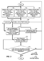
- FIG. 3 is a flow chart of a system for developing an operational schedule in accordance with a disclosed embodiment
- FIG. 4A is an example of a well grouping in accordance with a disclosed embodiment
- FIG. 4B is an example of another well grouping in accordance with a disclosed embodiment
- FIG. 5 is an example of an operating methodology in accordance with a disclosed embodiment.
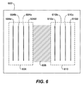
- FIG. 6 is an example of the use of a buffer zone in accordance with a disclosed embodiment.
- viscous oil as used herein means a hydrocarbon, or mixture of hydrocarbons, that occurs naturally and that has a viscosity of at least 10 cP (centipoise) at initial reservoir conditions. Viscous oil includes oils generally defined as “heavy oil” or “bitumen”. Bitumen is classified as an extra heavy oil, with an API gravity of about 10° or less, referring to its gravity as measured in degrees on the American Petroleum Institute (API) Scale. Heavy oil has an API gravity in the range of about 22.3° to about 10°. The terms viscous oil, heavy oil, and bitumen are used interchangeably herein since they may be extracted using similar processes.
- in situ is a Latin phrase for “in the place” and, in the context of hydrocarbon recovery, refers generally to a subsurface hydrocarbon-bearing reservoir.
- in situ temperature means the temperature within the reservoir.
- an in situ oil recovery technique is one that recovers oil from a reservoir within the earth.
- formation refers to a subterranean body of rock that is distinct and continuous.
- reservoir and “formation” may be used interchangeably.
- cyclic it is meant that any given well is intended to be used as both an injection well for injecting fluids into an underground reservoir and as a production well for producing fluids from the reservoir.
- non-cyclic it is meant that wells are not used for both injecting fluids into an underground reservoir and producing fluids from the reservoir.
- Components of interest means components found in situ in the reservoir or components injected into the reservoir during the life of the operation, including but not limited to solvent, oil, water, and methane.
- One embodiment relates to a method for operating a solvent-dominated, cyclic or non-cyclic, oil recovery process using a liquid-phase or supercritical-phase injectant in order to minimize surface solvent storage while maintaining economic operating conditions.
- Solvent-dominated, non-cyclic recovery processes to which embodiments of the instant invention could be applied include, for instance, a heated solvent process using a SAGD-type well configuration, as described in Canadian Patent Number 2,351,148 to Nenniger et al.
- Embodiments of the instant invention could also be applied to Solvent-Assisted Steam-Assisted Gravity Drainage (SA-SAGD, described for instance in U.S. Pat. No. 6,708,759 to Leaute et al.), Liquid Addition to Steam for Enhanced Recovery (LASER, described for instance in Canadian Patent No. 1,246,993 (Vogel)), and solvent flooding (U.S. Pat. No. 4,510,997 to Fitch et al.).
- SA-SAGD Solvent-Assisted Steam-Assisted Gravity Drainage
- LASER Liquid Addition to Steam for Enhanced Recovery
- solvent flooding U.S. Pat. No. 4,510,997 to Fitch et al.
- Solvent-dominated, cyclic recovery processes to which embodiments of the instant invention could be applied include, for instance, CSPTM processes, referred to above.
- Embodiments of the invention could also be applied to solvent-dominated, non-cyclic recovery processes, for instance, VAPEX processes, referred to above.
- Solvent can be brought to the field from an external source by trucks ( 102 ) and/or a pipeline ( 104 ) and injected into wells designated as injector wells ( 108 ) in FIG. 1 .
- solvent Prior to injection, solvent may be stored in a surface storage tank ( 106 ).
- injector wells can be switched to production in the case of a cyclic operation, becoming producer wells ( 110 ) after a suitable bank of solvent ( 113 ) has been placed in the reservoir ( 116 ).
- the produced solvent may be separated from the oil ( 112 ), recompressed, and reused for reinjection ( 114 ) into the reservoir ( 116 ).
- the compressor ( 118 ), separator ( 120 ), injection pump ( 122 ), power supply ( 128 ) and flowline for secondary solvent components ( 126 ), diluent for example, are also illustrated.
- wells can be switched back to injection, becoming injector wells. In a cyclic process, this switching between injection and production modes for a given well occurs repeatedly.
- FIG. 1 also shows the flowlines within the solvent supply, injection, and production system.
- the lines with arrows indicate the flow direction within flowlines that connect the components of system.
- the flowlines are an injection flowline ( 121 ) flowing at rate Q INJECT through injection pump ( 122 ), a solvent recycle flowline ( 114 ) flowing at rate Q PRODUCE , a pipeline supply line ( 104 ) flowing at rate Q PIPELINE , a flowline delivering secondary solvent components ( 126 ) at rate Q SECONDARY , and a line ( 107 ) making deposits to or withdrawing solvent from tank ( 106 ) at rate Q STORAGE .
- Q INJECT Q PRODUCE +Q PIPELINE +Q SECONDARY +Q STORAGE .
- Q PIPELINE may be positive (delivering solvent to field) or negative (removing solvent from field).
- FIG. 2A is a plot of the active number of wells in the field operation ( 208 ) versus time ( 210 ). As shown in FIG. 2A , the number of active wells generally increases during the start-up phase, is generally about constant during the steady-state phase, and generally decreases during the late-life phase of the field operation.
- FIG. 2B is a plot of solvent rate ( 216 ) versus time ( 210 ) for both injected solvent Q INJECT ( 220 ) and produced solvent Q PRODUCE ( 222 ).
- the difference between the two quantities is the net solvent, Q NET .
- the number of active wells remains roughly constant, although it may deviate some.
- the net solvent demand Q NET may be continue to be similar to the net solvent supply available from the pipeline and/or storage tanks (refreshed periodically with trucking of solvent) as in Eq. 3.
- Important challenges in all three phases of a solvent-dominated cyclic recovery process are minimizing the capital costs, operating costs, and supply costs.
- important challenges are minimizing costs related to pipeline capacity, surface solvent storage, and underground solvent storage.
- Surface storage capacity is costly, especially when pressurization of the solvent above atmospheric pressure is required to store the solvent as a liquid at about 20° C. Therefore, it is desirable to minimize the volume of the costly solvent storage tank ( 106 ).
- Designing the capacity of the pipeline to minimize cost is also important. This is especially true since the total field solvent demand (Q NET ) may vary over the operating life of the field, but pipeline solvent supply is typically near a uniform rate. Therefore, it is desirable to minimize the variation of the pipeline supply rate (Q PIPELINE ) over time.
- solvent storage may be particularly challenging to manage when the injection rates and production rates of wells differ dramatically. For instance, solvent injection rates can be 1 to 20 times higher than solvent production rates. In addition, for a cyclic process, individual well injection rates can vary dramatically in any given cycle (i.e., cycling between no injection and a maximum injection rate) and over the life of the well (i.e., injection rates can vary from one cycle to another).
- solvent is distributed to a set of wells terminating in an underground oil reservoir, where the operation is managed to minimize the surface solvent storage by minimizing the variation in the net solvent injection rate over the set of wells, into the reservoir (see FIG. 3 , described further below), over a certain period of time.
- the rate over a time period times the length of the time period is often called the cumulative volume. For example, if a withdrawal rate of 100 m 3 per day is expected over a period of 7 days, a tank containing at least 700 m 3 of solvent is required if no other solvent is delivered to the tank. If a deposition rate of 50 m 3 per day is expected over a period of 10 days, then a tank containing at least 500 m 3 of empty volume (ullage) is required.
- volume of storage required for N time periods may be expressed mathematically as the maximum value of the absolute value of the cumulative volume of the depositions/withdrawals for all time periods ⁇ t.
- Eq. 10 may be equivalently expressed using other means, including integral calculus.
- the volume of required storage depends directly on the rates and durations of withdrawals from, and depositions, to storage.
- FIG. 2C illustrates a time series of withdrawing solvent from the storage tank ( 230 ), depositing solvent to the tank ( 232 ), and then further withdrawing solvent from the tank ( 234 ).
- the top portion of FIG. 2C shows how the rate of deposition in (Q STORAGE ⁇ 0) for withdrawal from (Q STORAGE >0) the tank changes over time.
- the bottom portion of FIG. 2C shows the cumulative volume deposited (V STORAGE ⁇ 0) or withdrawn (V STORAGE >0) since the beginning of the time period.
- V STORAGE 12 m 3
- V STORAGE ⁇ 18 m 3
- solvent supply can be trucked in or brought in via a supply pipeline at a near constant daily rate (for example, Q PIPELINE ), operating the process such that the net injected solvent (Q NET ) into the underground oil reservoir matches, or is close to, this constant daily supply rate with minimal variation will minimize the surface solvent storage required.
- Q PIPELINE constant daily rate
- each well operates in a cyclic or periodic fashion, injecting solvent during one portion of its cycle and producing solvent during another portion.
- minimize[ing] is used herein, its use is not intended to imply that full minimization is required. That is, advantages may be achieved by reducing, without fully mathematically minimizing, the value at issue.
- optimization[ing] is not intended to imply full mathematical optimization.
- Mathematical methods for minimizing include, for example, downhill simplex, conjugate gradient, Monte Carlo based, genetic algorithms, simulated annealing, and other methods well known in the art. In mathematical optimization algorithms an objective variable (for example, solvent storage requirement or oil production), is minimized or maximized subject to particular constraints (for example, bounds on reasonable values of factors affecting the objective variable).
- Q NET net solvent injected
- the net solvent injection rate of the field may be computed from the sum over all the set of individual wells,
- Q NET ⁇ ( t ) ⁇ SET ⁇ q INJECT ⁇ ( t ) - ⁇ SET ⁇ q PRODUCE ⁇ ( t ) , ( 11 )
- the injection rate q INJECT (t) and production rate q PRODUCE (t) vs. time for a well may be referred to together as a “well profile.”
- One measure of variance is the maximum net injected solvent volume during a time period divided by the average net injected solvent volume over the same time period,
- variance max ⁇ [ Q NET ⁇ ( t ) ] average ⁇ [ Q NET ⁇ ( t ) ] , ( 12 )
- measures of variance that use the concept of standard deviation, make use of different length time periods, or are expressed in terms of volume rather than rate.
- the following non-limiting quantitative examples of minimizing are provided. In a first example, applying directly Eq. 12, it may be desirable to minimize the variation in net solvent injection rate to below 10% over a daily period.
- the selected injection and production schedule reduce the variation in the net solvent injection rate to an amount where an average or maximum daily difference between the injected and produced solvent volumes from the set of wells is within 20% of an average difference over a time period of one month. In a further example, it may be desirable that the selected injection and production schedule reduce the variation in the net solvent injection rate to an amount where an average hourly difference between the injected and produced solvent volumes from the set of wells is within 50% of an average difference over a time period of one day. Relatively speaking, large variances for short periods of time may be acceptable because they do not result in large solvent storage demands, but over longer periods of time the average variance should be smaller. Variances over hourly periods such as twelve hours, the length of an oilfield worker shift, may be the most practical time period in some instances.
- Computer simulation may be used to design solvent volume management schemes for a set of injecting and producing wells. More specifically, reservoir simulation, when combined with an optimization algorithm, may be a particularly effective tool for designing solvent volume management schemes. With reference to FIG. 3 , to balance the net solvent injected into a set of wells, a computer simulation procedure may be used to optimize the process in which the computer simulation procedure may comprise steps that use a reservoir simulator and/or an optimization algorithm, or “scheduler”.
- FIG. 3 is a flow chart of a system for developing an operational schedule in accordance with a disclosed embodiment.
- the first step is to generate well profile estimates which may include “estimating solvent injection and production rates”.
- the term “rate” as used herein may be an instantaneous rate or a rate over a time period (i.e. estimating a volume injected or produced over a time period).
- the well profiles may be generated using field measurements ( 300 ) of existing wells (perhaps pilot or test wells), computer reservoir simulation ( 302 ), and/or other analytical or theoretical methods ( 304 ).
- One embodiment is denoted as the “Main Process” ( 320 ) and alternate embodiments are denoted as “Alternate Process” ( 321 ).
- the preferred starting step is step ( 302 ), the prediction of well profiles using simulation.
- the reservoir simulator ( 302 ) may be used to predict one or more of:
- the next step is to select a set of the generated profiles ( 306 ).
- the selection may be based on judgment of which profiles are likely to form optimal groups or which profiles are most certain. If no judgment is made, the set of profiles may consist of all the generated profiles.
- the preferred step ( 310 ) is to use an optimization algorithm to minimize the variation in time of the net solvent injected.
- the optimization algorithm ( 310 ), also called a “scheduler,” may be used to minimize the variation in time of the net solvent injected into the set of wells by taking the selected set of well profiles ( 306 ) for one or more of the individual wells in the set of wells and scheduling the wells using one of more of the following optimization methods: operating wells in a group as a unit, offsetting the injection start-up dates for one or more wells, varying the injection cycle length for one or more wells, varying the idling or soak period between injection and production cycles for one or more wells, varying the production cycle length for one or more wells, varying the idling or soak period between production and injection cycles for one or more wells, using idling wells to store solvent, recycling the produced solvent from any well to be reinjected into any well using separation and recompression facilities, using above ground storage capacity, or using depleted reservoirs for solvent storage underground.
- the optimization algorithm observes a set of constraints ( 312 ) that may include economic and
- the well grouping strategy is identified with or without optimization, it may be useful to test the grouping strategy using reservoir simulation comprising at least two wells ( 314 ).
- the optimization algorithm treats each well's profile as independent of every other well's profile. In actual field operations, this not true once wells begin to interact.
- a reservoir simulator can account for the interdependent nature of the wells' profiles.
- the field-wide net solvent injected predicted during step ( 314 ) is typically more trustworthy than that predicted by the optimization tool during step ( 310 ). However, it may also be appropriate to proceed from step ( 310 ) directly to step ( 316 ).
- FIG. 3 states the optimization objective as obtaining an optimized quantity that is acceptable given the constraints ( 312 ) and other economic objectives.
- one optimization objective may be that the variation in the net solvent injected is low ( 316 ).
- Other objectives may include ensuring that the surface solvent storage is minimized, the underground storage is minimized, or that the variation in the pipeline supply is acceptable.
- new well grouping strategies may be identified ( 308 ), new well profile selections may be repeated ( 306 ), or new well profile estimations may be carried out via new measurement ( 300 ), simulation ( 302 ), or calculation ( 304 ).
- optimization 310
- optimization may be repeated using the same or different constraints ( 312 ). If the objectives are met, the selection process is terminated.
- An alternative embodiment is to use field data to estimate well profiles ( 300 ) and subsequently minimize the variation in the net solvent injection rate or other quantity.
- Field measurements may include one or more of: the injection rates and compositions, production rates and compositions, as well as durations of injection, production, and idling times.
- This alternative embodiment may also be used in conjunction with the computer simulation approach ( 302 ) to generating well profiles as previously described.
- An alternative embodiment uses analytic models to estimate well profiles ( 304 ) and subsequently minimize the variation in the net solvent injection rate. This alternative embodiment may also be used in conjunction with either the computer simulation approach to estimating well profiles ( 302 ) or the field data approach to estimating well profiles ( 300 ) as previously described.
- FIG. 4A and FIG. 4B Two embodiments of a strategy are shown in FIG. 4A and FIG. 4B . With reference to FIG. 3 , these embodiments follow a path through one or more of ( 300 ), ( 302 ), and ( 306 ), and then ( 306 ) and ( 308 ).
- FIG. 4A illustrates a grouping strategy for a set of wells that are operated in a largely non-cyclic manner.
- FIG. 4B illustrates a grouping strategy for set of wells that are operated in a largely cyclic manner.
- a set ( 402 ) of eight wells ( 422 ) may be divided into two subsets of wells ( 406 , 408 ).
- the first subset ( 406 ) comprises at least two wells from the set of wells where each well cycles between injecting solvent and not significantly injecting solvent.
- “Not significantly injecting” solvent means injecting less than 10% (including 0%) of a maximum injection rate in a cycle for a well.
- “Not significantly producing” fluids means producing less than 10% (including 0%) of a maximum production rate in a cycle for a well.
- each well cycles between a period of injection and a period of idling, as in a VAPEX recovery process employing solvent vapor injection wells and solvent/oil production wells.
- the second subset ( 408 ) comprises at least two wells from the set of wells where each well cycles between producing fluids and not significantly producing fluids.
- a method may be employed where the first subset of wells ( 406 ) is further split into two or more groups ( 414 , 416 ) where all wells in a group have similar injection cycle schedules, and solvent is injected into the wells in the first subset ( 406 ) using injection cycle schedules which are offset in time between groups so as to minimize fluctuations in the overall solvent injection rate to the set of wells ( 402 ).
- a “similar injection cycle schedule” means that the wells are all injecting at approximately the same rates for approximately equivalent durations of time. Thus, the composition of the injectant, rate of injection, and duration of injection are approximately equivalent for each similar injection cycle schedule. “Approximately the same” and “approximately equivalent” means about ⁇ 50%, or more preferably ⁇ 20%, or most preferably ⁇ 10%. Because a “well profile” includes both the injection and production schedule, wells with a similar injection cycle schedule will have a similar well profile unless the idle periods differ substantially. In the embodiment of FIG. 4A , the groups of wells may be operated such that the starting time of a given injection cycle for one group of wells is offset from the starting time of one of the other groups of wells. This strategy assists in the overall balance of net solvent injected (Q NET ) over the set of wells.
- Q NET net solvent injected
- Grouping wells may also help in managing the overall oil recovery from the reservoir. Grouping allows for wells undergoing similar operations (injection, production, idling) and in a similar stage of life (early operation, late-life operation, etc.) to be placed physically in proximity to one another. This proximal placing of wells undergoing similar operation may be preferred, especially early in the process, since it can prevent adjacent wells from being offset in such a way that one well is injecting solvent while an adjacent well is producing fluids from the reservoir. If one well is injecting solvent while an adjacent well is producing fluids, a large pressure gradient between the two wells is created, potentially leading to undesired early breakthrough of solvent from one well to another, decreasing the overall efficiency of the process and reducing the potential overall oil recovery.
- the two subsets may have one or more wells in common as shown in FIG. 4B .
- FIG. 4B shows that all wells are common between the two subsets and are shown as one combined subset ( 410 ). Therefore, all the wells cycle between significantly injecting solvent and significantly producing solvent/oil.
- Such a grouping strategy is appropriate for a process where the wells are largely cyclic, for example CSPTM processes.
- the combined subsets are further split into two groups ( 414 , 416 ).
- all wells in a group have similar injection cycle schedules. However, because the injection wells are also producer wells, they also have similar production schedules. The injection and production schedules of the two groups are offset so that the variation in the net solvent injection rate (Q NET ) is minimized.
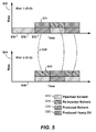
- FIG. 5 An alternative to the preferred operating methodology presented in FIG. 3 , where a computer simulation is used during steps ( 302 ), ( 310 ), and ( 314 ) to manage the net injected solvent, is a simpler pair balancing methodology, an example of which is presented in FIG. 5 .
- the methodology of FIG. 5 follows a path through ( 304 ), ( 306 ), and ( 308 ).
- FIG. 5 shows two rate ( 502 and 504 ) versus time ( 506 and 508 ) plots, one each for Well 1 ( 510 ) and Well 2 ( 512 ).
- each well belongs to a pair.
- a well pair comprises two wells.
- a well pair could comprise one longer well paired with, for example, two shorter wells.
- Other pairings are also possible and will be obvious to those skilled in the art.
- well groups may be paired.
- the fluid volume types are pipelined solvent ( 514 ), re-injected solvent ( 516 ), produced solvent ( 518 ), and produced heavy oil ( 520 ).
- volume is equal to the rate times the time and may be thought of visually as the area formed by the shaded boxes.
- one well is used to inject solvent into the reservoir while one well is simultaneously producing fluids from the reservoir.
- the injected solvent in the injection well is supplied by a near constant solvent supply plus the solvent produced from its paired-corresponding producing well.
- the pipeline solvent supply is near-constant, then the net solvent injected is also near-constant. In this way, the net injected solvent into any pair of wells is balanced with the incoming solvent supply, effectively eliminating, or reducing, the variation in the net injected solvent into the pair of wells.
- the injection rate of fluids into a well at a given stage in the development is allowed to exceed the production rate of fluids from a well at a similar stage in development, but in this embodiment, to balance the net injected solvent between a pair of wells, the injection rate of solvent into a given well can be reduced sufficiently so as to match the production of fluids from the corresponding well in its pair plus a near constant supply.
- the injection and combined solvent supply (recycled plus external) rates need not match exactly to effectively obtain a near-zero solvent storage operation.
- the schedule may comprise injecting solvent into one well of a pair at a rate substantially equal (+/ ⁇ 10% daily) to a rate of solvent simultaneously produced from the other well in the pair plus a substantially constant (+/ ⁇ 10% daily) solvent supply from a solvent source.
- the solvent injection rate during injection in Well 2 is 200 m 3 /day (100 m 3 /day from the solvent supply and 100 m 3 /day from the produced solvent from Well 1 ).
- the process continues for additional cycles.
- the total liquid production rate in this embodiment may vary since the oil production rate is not necessarily constant.
- the two wells in a pair of wells do not have to be in proximity to one another and it is preferred that the wells in a pair are actually separated by a buffer zone.
- a “buffer zone” is a zone between wells that renders the wells substantially independent of one another; that is, the effect of one well will not have a substantial effect on the other well.
- the set of wells may be divided into two groups, each of which contains only one well in any given well pair. These two groups can be separated by a buffer ( FIG.
- the set ( 600 ) of eight wells comprises a group ( 604 ) of four injecting wells ( 604 a , 604 b , 604 c , 604 d ) separated by a buffer zone ( 606 ) from a group ( 610 ) of four producing wells ( 610 a , 610 b , 610 c , 610 d ). If the groups were operated such that each well of group ( 604 ) was paired with a well of group ( 610 ), then well ( 604 a ) might be paired with well ( 610 a ), and similarly for the other wells.
- Another option for minimizing the variation in the net injected solvent, and thus the need for surface solvent storage involves using a subsurface reservoir with at least a fraction of the initial in situ fluids extracted, to store solvent. Once at least a portion of the in situ fluids from a reservoir have been produced, the reservoir can be used as a solvent bank to store excess solvent and supply solvent as needed.
- Solvent can be supplied via a supply pipeline or via trucking. Solvent supplied via a supply pipeline is often supplied at a constant daily supply rate, since a premium is often required to allow for variation in the solvent supply via pipeline. Solvent can also be progressively trucked in for start-up operation where less solvent may be needed than in full-field operation. This trucking could occur until plant capacity is reached in an economic fashion, which may be about 1 ⁇ 3 to 1 ⁇ 2 of the life of a single well. The maximum allowable daily solvent trucking rate may determine the plant and solvent recycling capacities. The number of new wells in start-up operation may be equal to the plant capacity divided by the predicted average calendar day oil rate per well in early cycles. In this scenario, solvent storage supply is desired to account for trucking interruptions, which can occur for several reasons including weather or supply disruptions. After steady operation has been established, solvent supply can be switched from trucking over to a pipeline.
- the excess produced solvent can be sent to another solvent injection site or transported to a vendor facility for resale.
- This solvent can be shipped via either pipeline, trucking, or a combination of trucking and pipeline.
- the remaining recoverable solvent can be produced by depressurizing a portion of the reservoir below the vaporization pressure of the solvent at reservoir temperature to recover as much of the injected solvent as is economically feasible.
- the pressure in the reservoir in contact with the injected solvent will drop to the pressure of the minimum allowable pressure to recover the maximum amount of solvent possible.
- An OISR may be defined for each producing well over any period of time for which there is both injection and production. Let's consider how to maximize the field-wide OISR under several different circumstances.
- the capacity of the recycle flowline ( 121 ) carrying the combined pipelined and produced solvent supply is necessarily of limited capacity. If it were to reach maximum capacity and the external solvent supply were already zero, it would be desirable to choke back, or decrease, the flow rate of recycled solvent from the wells with the lowest OISR. This situation might occur during the steady phase ( 226 ) of field life.
- the wells have differential solvent production rates and it is desirable to know which wells should be choked back.
- the following may be carried out: (1) Calculate a solvent efficiency measure (such as OISR) using the solvent and oil flow rates for every well that feeds the solvent recycle line; (2) Rank all the wells from most to least solvent efficient; and (3) Reduce the solvent flow rate (including possible reduction to zero) of the least efficient well by reducing its gross production rate. Gross production rate may be decreased by increasing the producing pressure of the well. While reducing the solvent flow rate of the least efficient well is one approach, there may be instances where one would chose to produce at least one well of relatively lower efficiency at a lower rate than at least one well of relatively higher efficiency. For example, if ten wells are ranked from 1 (least efficient) to 10 (most efficient), reducing the flow rate of well 2 instead of well 1 could also be beneficial under the circumstances set out above.
- a solvent efficiency measure such as OISR
- the concept of choking back the solvent production rate by increasing the producing pressure is especially important in SDRPs. If the producing pressure is above the vaporization pressure, the solvent will be produced primarily as a liquid, and if the producing pressure is lower than the vaporizing pressure, the solvent will be produced primarily as a vapor. There is no analogy of this concept to steam-based processes, where substantially all of the steam is condensed to liquid phase water prior to production. Producing SDRP wells may therefore be operated either above or below the vaporization pressure, resulting in relatively low volumes of produced liquid phase solvent or relatively high volumes of produced vapor phase solvent. If surface solvent storage is not available, it may be advantageous to operate the wells above the vaporization pressure of the solvent such that solvent remains in the liquid phase and underground, rather than being produced.
- blowdown The process of vaporizing the solvent in the reservoir, and producing as much remaining solvent in the vapor phase as possible is known as “blowdown”.
- the specific timing of blowdown whether it occurs after every injection and production cycle or whether it occurs only during the final cycle of a CSDRP, may be an effective lever for controlling produced solvent volumes.
- Another strategy for storing solvent underground is to operate a greater fraction of the producing wells above their vaporization pressure, storing solvent in the liquid state in the reservoir.
- the maximization of profitability might best be served by reducing the pressure of the producing well to as low a pressure as possible in order to recover the solvent in the vapor phase as quickly as possible, and forego oil production in the process. That is, there is a trade-off between a long period of low-rate oil production with some associated solvent in a relatively high-pressure pressure operation versus a short period of low-rate oil production and a relatively higher rate of solvent production at low-pressure.
- operational costs such as compression
- well production and injection profiles are known
- direct optimization of a measure of profitability may be accomplished via the procedure of FIG. 3 where the optimized Variable ( 310 ) is a measure of profitability.
- One particular embodiment comprises operation for a solvent-dominated cyclic recovery process where solvent is trucked in, stored in inventory, injected into the reservoir, produced from the reservoir, separated from the produced reservoir fluids, and recycled with a phased-in solvent supply from pipelining where the following steps are followed:
- “Blow down” means that the pressure in a portion of the reservoir is dropped to below that of the vapor pressure of the solvent at the reservoir temperature, and production of the reservoir fluids along with the solvent is continued until either an economic limit is reached or another cutoff criteria is reached.
- another embodiment comprises operation for a solvent-dominated cyclic recovery process where solvent is supplied via a pipeline at a near constant rate, optionally stored in inventory, injected into the reservoir, produced from the reservoir, separated from the produced reservoir fluids, and recycled where the following steps are followed:
- the system for developing an operational schedule may comprise:
- a reservoir simulator that predicts one or more of: individual well injection rates, production rates, injected volumes, and produced volumes for one or more of the components of interest;
- a scheduler that takes individual well injection and production rates and groups wells together to optimize total solvent usage to within ⁇ 10% of the supply rate by one or more of the following means:
- Table 1 outlines the operating ranges for CSDRPs of some embodiments. The present invention is not intended to be limited by such operating ranges.
- Injectant Additional injectants may Only diluent, and only when composition, include CO 2 (up to about 30%), needed to achieve adequate additive C 3+ , viscosifiers (for example injection pressure. diesel, viscous oil, bitumen, diluent), ketones, alcohols, sulphur dioxide, hydrate inhibitors, and steam.
- Injectant phase & Solvent injected such that at Solvent injected as a liquid, and Injection the end of injection, greater most solvent injected just under pressure than 25% by mass of the fracture pressure and above solvent exists as a liquid in the dilation pressure, reservoir, with no constraint as P fracture > P injection > P dilation > to whether most solvent is P vaporP .
- Well length As long of a horizontal well as 500 m-1500 m (commercial well). can practically be drilled; or the entire pay thickness for vertical wells.
- vertical wells high angle slant wells & multi-lateral wells.
- infill injection and/or production wells (of any type above) targeting bypassed hydrocarbon from surveillance of pattern performance.
- Well orientation Orientated in any direction.
- the range of the A low pressure below the vapor producing MPP should be, on the low pressure of the main solvent, pressure (MPP) end, a pressure significantly ensuring vaporization, or, in the below the vapor pressure, limited vaporization scheme, a ensuring vaporization; and, on high pressure above the vapor the high-end, a high pressure pressure.
- MPP main solvent
- well is the oil rate is at about 0.8 ⁇ unable to sustain hydrocarbon CDOR.
- switch to flow (continuous or injection when rate equals 20-40% intermittent) by primary of the max rate obtained during production against the cycle. backpressure of gathering system or well is “pumped off” unable to sustain flow from artificial lift.
- well is out-of-synch with adjacent well cycles.
- Well is unable to During production, an optimal sustain hydrocarbon flow strategy is one that limits gas (continuous or intermittent) by production and maximizes liquid primary production against from a horizontal well. backpressure of gathering system with/or without compression facilities.
- Oil to Solvent Begin another cycle if the Begin another cycle if the OISR of Ratio OISR of the just completed the just completed cycle is above cycle is above 0.15 or 0.3. economic threshold.
- embodiments may be formed by combining two or more parameters and, for brevity and clarity, each of these combinations will not be individually listed.
- diluent means a liquid compound that can be used to dilute the solvent and can be used to manipulate the viscosity of any resulting solvent-bitumen mixture.
- the diluent is typically a viscous hydrocarbon liquid, especially a C 4 to C 20 hydrocarbon, or mixture thereof, is commonly locally produced and is typically used to thin bitumen to pipeline specifications. Pentane, hexane, and heptane are commonly components of such diluents. Bitumen itself can be used to modify the viscosity of the injected fluid, often in conjunction with ethane solvent.
- the diluent may have an average initial boiling point close to the boiling point of pentane (36° C.) or hexane (69° C.) though the average boiling point (defined further below) may change with reuse as the mix changes (some of the solvent originating among the recovered viscous oil fractions).
- more than 50% by weight of the diluent has an average boiling point lower than the boiling point of decane (174° C.). More preferably, more than 75% by weight, especially more than 80% by weight, and particularly more than 90% by weight of the diluent, has an average boiling point between the boiling point of pentane and the boiling point of decane.
- the diluent has an average boiling point close to the boiling point of hexane (69° C.) or heptane (98° C.), or even water (100° C.).
- more than 50% by weight of the diluent (particularly more than 75% or 80% by weight and especially more than 90% by weight) has a boiling point between the boiling points of pentane and decane. In other embodiments, more than 50% by weight of the diluent has a boiling point between the boiling points of hexane (69° C.) and nonane (151° C.), particularly between the boiling points of heptane (98° C.) and octane (126° C.).
- boiling point of the diluent we mean the boiling point of the diluent remaining after half (by weight) of a starting amount of diluent has been boiled off as defined by ASTM D 2887 (1997), for example.
- the average boiling point can be determined by gas chromatographic methods or more tediously by distillation. Boiling points are defined as the boiling points at atmospheric pressure.
- Embodiments of the invention can be represented as a software product stored in a machine-readable medium (also referred to as a computer-readable medium, a processor-readable medium, or a computer usable medium having a computer-readable program code embodied therein).
- the machine-readable medium can be any suitable tangible medium, including magnetic, optical, or electrical storage medium including a diskette, compact disk read only memory (CD-ROM), memory device (volatile or non-volatile), or similar storage mechanism.
- the machine-readable medium can contain various sets of instructions, code sequences, configuration information, or other data, which, when executed, cause a processor to perform steps in a method according to an embodiment of the invention.
- Those of ordinary skill in the art will appreciate that other instructions and operations necessary to implement the described invention can also be stored on the machine-readable medium.
- Software running from the machine-readable medium can interface with circuitry to perform the described tasks.
Landscapes
- Engineering & Computer Science (AREA)
- Geology (AREA)
- Life Sciences & Earth Sciences (AREA)
- Physics & Mathematics (AREA)
- Mining & Mineral Resources (AREA)
- Environmental & Geological Engineering (AREA)
- Fluid Mechanics (AREA)
- General Life Sciences & Earth Sciences (AREA)
- Geochemistry & Mineralogy (AREA)
- Business, Economics & Management (AREA)
- General Business, Economics & Management (AREA)
- General Physics & Mathematics (AREA)
- Theoretical Computer Science (AREA)
- Production Of Liquid Hydrocarbon Mixture For Refining Petroleum (AREA)
Abstract
Description
- alternating between injecting and not significantly injecting into at least two groups of injection wells, wherein wells within a first group have similar injection schedules; wells within a second group have similar injection schedules; wells of the first group have injection schedules that are offset in time from the wells of the second group; and alternating between producing and not significantly producing in production wells that are distinct from the injection wells. The similar injection schedules may be where the injection schedules include injecting at approximately the same rates for approximately equivalent durations of time. The injection schedules that are offset in time may be where, for at least 10% of a time, the wells of the first group are injecting while the wells of the second group are not significantly injecting. The schedule may further comprise operating wells with offset production schedules, wherein: wells within the first group have similar production schedules, wells within the second group have similar production schedules; and wells of the first group have production schedules that are offset in time from the wells of the second group. The similar production schedules may be where the production schedules include producing at approximately the same rates for approximately equivalent durations of time. The production schedules that are offset in time may be where, for at least 10% of a time, the wells of the first group are producing while the wells of the second group are not significantly producing.
Q INJECT =Q PRODUCE +Q PIPELINE +Q SECONDARY +Q STORAGE. (1)
Depending on whether the pipeline (104) is delivering solvent to or carrying solvent from the field operation, QPIPELINE may be positive (delivering solvent to field) or negative (removing solvent from field). Depending on whether the tank (106) is supplying solvent to or accepting solvent from the field operation, QSTORAGE may be positive (supplying solvent to field) or negative (accepting solvent from field). If no secondary components are needed, Eq. (1) becomes,
Q INJECT =Q PRODUCE +Q PIPELINE +Q STORAGE. (2)
Because the produced solvent may be recycled, it is useful to frame the discussion of solvent supply to the field in terms of “net solvent,” which is given by the difference between the injected and produced solvent rates,
Q NET =Q INJECT −Q PRODUCE =Q PIPELINE +Q STORAGE. (3)
Q NET =Q INJECT =Q PIPELINE +Q STORAGE>0. (4)
At some point during the start-up phase of the field operation, some wells do begin producing (QPRODUCE≠0), but they still do not provide enough solvent to supply the injection wells. Therefore, make-up solvent must continue to be supplied by pipeline and/or from storage, and the full expression describing the net solvent demand is Eq. 3 (all terms non-zero). But, if storage has already been exhausted and has not been refreshed (QSTORAGE=0), then by Eq. 3,
Q NET =Q INJECT −Q PRODUCE =Q PIPELINE>0. (5)
Q NET =Q INJECT −Q PRODUCE=0. (6)
Q NET =Q INJECT −Q PRODUCE<0. (7)
The direction of flow in the pipeline may then be reversed (QPIPELINE<0) and solvent may be sent by pipeline to a facility for resale or to a new site for reuse.
Q STORAGE =Q INJECT −Q PRODUCE −Q PIPELINE −Q NET −Q PIPELINE. (8)
Eq. 8 is applicable over any period of time. The volume of solvent storage required during a time period (Δt) of deposition or withdrawal is a function of the average deposition or withdrawal rate during the time period times the length of the time period,
V STORAGE =Q STORAGE Δt. (9)
The rate over a time period times the length of the time period is often called the cumulative volume. For example, if a withdrawal rate of 100 m3 per day is expected over a period of 7 days, a tank containing at least 700 m3 of solvent is required if no other solvent is delivered to the tank. If a deposition rate of 50 m3 per day is expected over a period of 10 days, then a tank containing at least 500 m3 of empty volume (ullage) is required.
Those skilled in the art will recognize that Eq. 10 may be equivalently expressed using other means, including integral calculus. For purposes of understanding embodiments of the invention, it is sufficient to understand that the volume of required storage depends directly on the rates and durations of withdrawals from, and depositions, to storage.
Q NET(t)=Q INJECT(t)−Q PRODUCE(t)−Q PIPELINE(t)+Q STORAGE(t), (10)
from the individual injection rates and production rates of all the wells in the set of wells, and to further analyze the variance of QNET(t). The net solvent injection rate of the field may be computed from the sum over all the set of individual wells,
The injection rate qINJECT(t) and production rate qPRODUCE(t) vs. time for a well may be referred to together as a “well profile.” One measure of variance is the maximum net injected solvent volume during a time period divided by the average net injected solvent volume over the same time period,
Those skilled in the art will appreciate that there are many alternative definitions of variance; for example, measures of variance that use the concept of standard deviation, make use of different length time periods, or are expressed in terms of volume rather than rate. The following non-limiting quantitative examples of minimizing are provided. In a first example, applying directly Eq. 12, it may be desirable to minimize the variation in net solvent injection rate to below 10% over a daily period. In another example, it may be desirable that the selected injection and production schedule reduce the variation in the net solvent injection rate to an amount where an average or maximum daily difference between the injected and produced solvent volumes from the set of wells is within 20% of an average difference over a time period of one month. In a further example, it may be desirable that the selected injection and production schedule reduce the variation in the net solvent injection rate to an amount where an average hourly difference between the injected and produced solvent volumes from the set of wells is within 50% of an average difference over a time period of one day. Relatively speaking, large variances for short periods of time may be acceptable because they do not result in large solvent storage demands, but over longer periods of time the average variance should be smaller. Variances over hourly periods such as twelve hours, the length of an oilfield worker shift, may be the most practical time period in some instances.
-
- individual well injection rates vs. time, qINJECT(t);
- individual well production rates vs. time, qPRODUCE(t);
- average rates qINJECT and qPRODUCE over a time period; and
- total volumes vINJECT and vPRODUCE over a time period,
for one or more of the components in the simulation. The primary component of interest is solvent.
Q NET =Q PIPELINE, (14)
and that the injected solvent equals the solvent supplied by pipeline plus the produced (recycled) solvent,
Q INJECT =Q PIPELINE +Q PRODUCE. (15)
Produced Oil to Injected Solvent Ratio=Q PRODUCE OIL /Q INJECT SOLVENT. (16)
-
- a. Predict the optimal injection and production rates for each well in the pad as well as the potential range of sustainable injection and production rates;
- b. Evaluate the optimal plant and solvent recycling capacity;
- c. Determine a supply rate for the pipeline based on supply constraints, recycling constraints, the average production rate expected for a given well, the number of wells in the pad, the average fraction by volume of the reservoir fluids at reservoir conditions that is comprised of the produced solvent, and the expected injection rate for a given well;
-
- a. Operating wells in a group as a unit;
- b. Offsetting well group start up dates;
- c. Varying injection cycle length;
- d. Varying idling or soak period between the injection and production cycles;
- e. Varying production cycle length;
- f. Varying idling or soak period between the production and injection cycles;
- g. Using idling wells as solvent storage;
- h. Recycling the produced solvent to be reinjected into a group of wells using separation and recompression facilities;
- i. Installing an above ground storage capacity for solvent;
- j. Using depleted reservoirs for solvent storage below the surface.
| TABLE 1 |
| Operating Ranges for a CSDRP. |
| Parameter | Broader Embodiment | Narrower Embodiment |
| Injectant volume | Fill-up estimated pattern pore | Inject, beyond a pressure |
| volume plus 2-15% of | threshold, 2-15% (or 3-8%) of | |
| estimated pattern pore volume; | estimated pore volume. | |
| or inject, beyond a pressure | ||
| threshold, for a period of time | ||
| (for example weeks to | ||
| months); or inject, beyond a | ||
| pressure threshold, 2-15% of | ||
| estimated pore volume. | ||
| Injectant | Main solvent (>50 mass %) C2-C5. | Main solvent (>50 mass %) is |
| composition, | Alternatively, wells may be | propane (C3). |
| main | subjected to compositions | |
| other than main solvents to | ||
| improve well pattern | ||
| performance (i.e. CO2 flooding | ||
| of a mature operation or | ||
| altering in situ stress of | ||
| reservoir). | ||
| Injectant | Additional injectants may | Only diluent, and only when |
| composition, | include CO2 (up to about 30%), | needed to achieve adequate |
| additive | C3+, viscosifiers (for example | injection pressure. |
| diesel, viscous oil, bitumen, | ||
| diluent), ketones, alcohols, | ||
| sulphur dioxide, hydrate | ||
| inhibitors, and steam. | ||
| Injectant phase & | Solvent injected such that at | Solvent injected as a liquid, and |
| Injection | the end of injection, greater | most solvent injected just under |
| pressure | than 25% by mass of the | fracture pressure and above |
| solvent exists as a liquid in the | dilation pressure, | |
| reservoir, with no constraint as | Pfracture > Pinjection > Pdilation > | |
| to whether most solvent is | PvaporP. | |
| injected above or below | ||
| dilation pressure or fracture | ||
| pressure. | ||
| Injectant | Enough heat to prevent | Enough heat to prevent hydrates |
| temperature | hydrates and locally enhance | with a safety margin, |
| wellbore inflow consistent with | Thydrate + 5° C. to Thydrate + | |
| Boberg-Lantz model. | 50° C. | |
| Injection rate | 0.1 to 10 m3/day per meter of | 0.2 to 2 m3/day per meter of |
| completed well length (rate | completed well length (rate | |
| expressed as volumes of liquid | expressed as volumes of liquid | |
| solvent at reservoir conditions). | solvent at reservoir conditions). | |
| Rates may also be designed to | ||
| allow for limited or controlled | ||
| fracture extent, at fracture | ||
| pressure or desired solvent | ||
| conformance depending on | ||
| reservoir properties. | ||
| Threshold | Any pressure above initial | A pressure between 90% and |
| pressure | reservoir pressure. | 100% of fracture pressure. |
| (pressure at | ||
| which solvent | ||
| continues to be | ||
| injected for either | ||
| a period of time | ||
| or in a volume | ||
| amount) | ||
| Well length | As long of a horizontal well as | 500 m-1500 m (commercial well). |
| can practically be drilled; or the | ||
| entire pay thickness for vertical | ||
| wells. | ||
| Well | Horizontal wells parallel to | Horizontal wells parallel to each |
| configuration | each other, separated by some | other, separated by some regular |
| regular spacing of 60-600 m; | spacing of 60-320 m. | |
| Also vertical wells, high angle | ||
| slant wells & multi-lateral wells. | ||
| Also infill injection and/or | ||
| production wells (of any type | ||
| above) targeting bypassed | ||
| hydrocarbon from surveillance | ||
| of pattern performance. | ||
| Well orientation | Orientated in any direction. | Horizontal wells orientated |
| perpendicular to (or with less than | ||
| 30 degrees of variation) the | ||
| direction of maximum horizontal in | ||
| situ stress. | ||
| Minimum | Generally, the range of the | A low pressure below the vapor |
| producing | MPP should be, on the low | pressure of the main solvent, |
| pressure (MPP) | end, a pressure significantly | ensuring vaporization, or, in the |
| below the vapor pressure, | limited vaporization scheme, a | |
| ensuring vaporization; and, on | high pressure above the vapor | |
| the high-end, a high pressure | pressure. At 500 m depth with pure | |
| near the native reservoir | propane, 0.5 MPa (low)-1.5 MPa | |
| pressure. For example, | (high), values that bound the 800 kPa | |
| perhaps 0.1 MPa-5 MPa, | vapor pressure of propane. | |
| depending on depth and mode | ||
| of operation (all-liquid or limited | ||
| vaporization). | ||
| Oil rate | Switch to injection when rate | Switch when the instantaneous oil |
| equals 2 to 50% of the max | rate declines below the calendar | |
| rate obtained during the cycle; | day oil rate (CDOR) (for example | |
| Alternatively, switch when | total oil/total cycle length). Likely | |
| absolute rate equals a pre-set | most economically optimal when | |
| value. Alternatively, well is | the oil rate is at about 0.8 × | |
| unable to sustain hydrocarbon | CDOR. Alternatively, switch to | |
| flow (continuous or | injection when rate equals 20-40% | |
| intermittent) by primary | of the max rate obtained during | |
| production against | the cycle. | |
| backpressure of gathering | ||
| system or well is “pumped off” | ||
| unable to sustain flow from | ||
| artificial lift. Alternatively, well | ||
| is out-of-synch with adjacent | ||
| well cycles. | ||
| Gas rate | Switch to injection when gas | Switch to injection when gas rate |
| rate exceeds the capacity of | exceeds the capacity of the | |
| the pumping or gas venting | pumping or gas venting system. | |
| system. Well is unable to | During production, an optimal | |
| sustain hydrocarbon flow | strategy is one that limits gas | |
| (continuous or intermittent) by | production and maximizes liquid | |
| primary production against | from a horizontal well. | |
| backpressure of gathering | ||
| system with/or without | ||
| compression facilities. | ||
| Oil to Solvent | Begin another cycle if the | Begin another cycle if the OISR of |
| Ratio | OISR of the just completed | the just completed cycle is above |
| cycle is above 0.15 or | 0.3. | |
| economic threshold. | ||
| Abandonment | Atmospheric or a value at | For propane and a depth of 500 m, |
| pressure | which all of the solvent is | about 340 kPa, the likely lowest |
| (pressure at | vaporized. | obtainable bottomhole pressure at |
| which well is | the operating depth and well | |
| produced after | below the value at which all of the | |
| CSDRP cycles | propane is vaporized. | |
| are completed) | ||
Claims (21)
Applications Claiming Priority (2)
| Application Number | Priority Date | Filing Date | Title |
|---|---|---|---|
| CA2705643A CA2705643C (en) | 2010-05-26 | 2010-05-26 | Optimization of solvent-dominated recovery |
| CA2,705,643 | 2010-05-26 |
Publications (2)
| Publication Number | Publication Date |
|---|---|
| US20110295771A1 US20110295771A1 (en) | 2011-12-01 |
| US8899321B2 true US8899321B2 (en) | 2014-12-02 |
Family
ID=45022901
Family Applications (1)
| Application Number | Title | Priority Date | Filing Date |
|---|---|---|---|
| US13/084,256 Active 2032-04-29 US8899321B2 (en) | 2010-05-26 | 2011-04-11 | Method of distributing a viscosity reducing solvent to a set of wells |
Country Status (2)
| Country | Link |
|---|---|
| US (1) | US8899321B2 (en) |
| CA (1) | CA2705643C (en) |
Cited By (4)
| Publication number | Priority date | Publication date | Assignee | Title |
|---|---|---|---|---|
| US10487636B2 (en) | 2017-07-27 | 2019-11-26 | Exxonmobil Upstream Research Company | Enhanced methods for recovering viscous hydrocarbons from a subterranean formation as a follow-up to thermal recovery processes |
| US11002123B2 (en) | 2017-08-31 | 2021-05-11 | Exxonmobil Upstream Research Company | Thermal recovery methods for recovering viscous hydrocarbons from a subterranean formation |
| US11142681B2 (en) | 2017-06-29 | 2021-10-12 | Exxonmobil Upstream Research Company | Chasing solvent for enhanced recovery processes |
| US11261725B2 (en) | 2017-10-24 | 2022-03-01 | Exxonmobil Upstream Research Company | Systems and methods for estimating and controlling liquid level using periodic shut-ins |
Families Citing this family (8)
| Publication number | Priority date | Publication date | Assignee | Title |
|---|---|---|---|---|
| WO2014197687A1 (en) * | 2013-06-07 | 2014-12-11 | Shell Oil Company | Remediation of asphaltene-induced plugging of an oil-bearing formation |
| CN105308261A (en) | 2013-06-18 | 2016-02-03 | 国际壳牌研究有限公司 | Oil recovery system and method |
| BR112015032220A2 (en) | 2013-06-27 | 2017-08-22 | Shell Internationale Res Maatschappij | METHODS FOR TREATMENT OF A WELL BOREHOLE AND A WELLHOLE PRODUCTION FLOWLINE PENETRATING AN UNDERGROUND FORMATION, AND, SYSTEM FOR REPAIRING ASPHALTENE DEPOSITION |
| US10233727B2 (en) * | 2014-07-30 | 2019-03-19 | International Business Machines Corporation | Induced control excitation for enhanced reservoir flow characterization |
| CN109306858B (en) * | 2017-07-28 | 2021-01-29 | 中国石油天然气股份有限公司 | Polymer injection well online concentration device and method |
| US10975668B2 (en) * | 2018-03-29 | 2021-04-13 | Ge Inspection Technologies, Lp | Rapid steam allocation management and optimization for oil sands |
| US20240013120A1 (en) * | 2022-07-08 | 2024-01-11 | Saudi Arabian Oil Company | Development of potential readiness advisory tool (prat) |
| CN117189052B (en) * | 2023-08-21 | 2025-09-12 | 华美孚泰油气增产技术服务有限责任公司 | A method for optimizing single oil recovery rate by combined flooding of carbon dioxide injection and chemical agents |
Citations (241)
| Publication number | Priority date | Publication date | Assignee | Title |
|---|---|---|---|---|
| US849524A (en) | 1902-06-23 | 1907-04-09 | Delos R Baker | Process of extracting and recovering the volatilizable contents of sedimentary mineral strata. |
| US1246993A (en) | 1917-06-22 | 1917-11-20 | Jerome Payet | Apparatus for cleaning fabrics. |
| US2188012A (en) | 1933-02-06 | 1940-01-23 | Shell Dev | Method of separating high molecular mixtures |
| US2358183A (en) | 1939-02-03 | 1944-09-12 | Gulf Oil Corp | Cracking hydrocarbon oils |
| US2365591A (en) | 1942-08-15 | 1944-12-19 | Ranney Leo | Method for producing oil from viscous deposits |
| US2412765A (en) | 1941-07-25 | 1946-12-17 | Phillips Petroleum Co | Recovery of hydrocarbons |
| US2655465A (en) | 1951-07-24 | 1953-10-13 | Standard Oil Dev Co | Residuum coking and cracking |
| US3074481A (en) | 1959-09-25 | 1963-01-22 | Union Oil Co | Method for the improvement of areal sweep during secondary recovery |
| US3185634A (en) | 1961-07-14 | 1965-05-25 | Pan American Petroleum Corp | Oil recovery by foam drive |
| US3274101A (en) * | 1964-01-06 | 1966-09-20 | Exxon Production Research Co | Solvent recovery process |
| US3323588A (en) | 1964-09-28 | 1967-06-06 | Union Oil Co | Method of secondary recovery employing successive foam drives of different ionic characteristics |
| US3342256A (en) | 1964-04-17 | 1967-09-19 | Union Oil Co | Method for recovering oil from subterranean formations |
| US3434544A (en) | 1966-12-22 | 1969-03-25 | Pan American Petroleum Corp | Method for conducting cyclic steam injection in recovery of hydrocarbons |
| US3608638A (en) | 1969-12-23 | 1971-09-28 | Gulf Research Development Co | Heavy oil recovery method |
| US3671419A (en) | 1970-02-27 | 1972-06-20 | Mobil Oil Corp | Upgrading of crude oil by combination processing |
| US3704990A (en) | 1971-06-04 | 1972-12-05 | Union Oil Co | Process for recovering oil from heterogeneous reservoirs |
| US3705625A (en) | 1971-10-22 | 1972-12-12 | Shell Oil Co | Steam drive oil recovery process |
| US3707189A (en) | 1970-12-16 | 1972-12-26 | Shell Oil Co | Flood-aided hot fluid soak method for producing hydrocarbons |
| US3739852A (en) | 1971-05-10 | 1973-06-19 | Exxon Production Research Co | Thermal process for recovering oil |
| US3782465A (en) | 1971-11-09 | 1974-01-01 | Electro Petroleum | Electro-thermal process for promoting oil recovery |
| CA940853A (en) | 1971-02-10 | 1974-01-29 | Michael J. Keaton | Process and apparatus for recovering oil from tar-oil emulsions |
| US3811503A (en) | 1972-07-27 | 1974-05-21 | Texaco Inc | Secondary recovery using mixtures of carbon dioxide and light hydrocarbons |
| US3818989A (en) | 1972-12-27 | 1974-06-25 | Texaco Inc | Method for preferentially producing petroleum from reservoirs containing oil and water |
| US3823777A (en) | 1973-05-04 | 1974-07-16 | Texaco Inc | Multiple solvent miscible flooding technique for use in petroleum formation over-laying and in contact with water saturated porous formations |
| US3878892A (en) | 1973-05-04 | 1975-04-22 | Texaco Inc | Vertical downward gas-driven miscible blanket flooding oil recovery process |
| US3908762A (en) | 1973-09-27 | 1975-09-30 | Texaco Exploration Ca Ltd | Method for establishing communication path in viscous petroleum-containing formations including tar sand deposits for use in oil recovery operations |
| US3945435A (en) | 1973-05-24 | 1976-03-23 | The Ralph M. Parsons Co. | In situ recovery of hydrocarbons from tar sands |
| US3946809A (en) | 1974-12-19 | 1976-03-30 | Exxon Production Research Company | Oil recovery by combination steam stimulation and electrical heating |
| US3948319A (en) | 1974-10-16 | 1976-04-06 | Atlantic Richfield Company | Method and apparatus for producing fluid by varying current flow through subterranean source formation |
| US3954141A (en) | 1973-10-15 | 1976-05-04 | Texaco Inc. | Multiple solvent heavy oil recovery method |
| US3956145A (en) | 1972-12-27 | 1976-05-11 | Texaco Inc. | Fluid for injection into a subterranean reservoir to displace hydrocarbons in the reservoir |
| US3958636A (en) | 1975-01-23 | 1976-05-25 | Atlantic Richfield Company | Production of bitumen from a tar sand formation |
| US3960214A (en) | 1975-06-06 | 1976-06-01 | Atlantic Richfield Company | Recovery of bitumen by steam injection |
| US3986557A (en) | 1975-06-06 | 1976-10-19 | Atlantic Richfield Company | Production of bitumen from tar sands |
| US4004636A (en) | 1975-05-27 | 1977-01-25 | Texaco Inc. | Combined multiple solvent and thermal heavy oil recovery |
| US4007787A (en) | 1975-08-18 | 1977-02-15 | Phillips Petroleum Company | Gas recovery from hydrate reservoirs |
| US4007785A (en) * | 1974-03-01 | 1977-02-15 | Texaco Inc. | Heated multiple solvent method for recovering viscous petroleum |
| US4008764A (en) | 1974-03-07 | 1977-02-22 | Texaco Inc. | Carrier gas vaporized solvent oil recovery method |
| US4010799A (en) | 1975-09-15 | 1977-03-08 | Petro-Canada Exploration Inc. | Method for reducing power loss associated with electrical heating of a subterranean formation |
| US4017383A (en) | 1975-05-15 | 1977-04-12 | Ralph M. Parsons Company | Solvent deasphalting process by solvent recovery at staged pressures |
| US4017583A (en) | 1974-02-07 | 1977-04-12 | Japan Atomic Energy Research Institute | Volitilization process for separation of molybdenum-99 from irradiated uranium |
| US4017388A (en) | 1969-08-22 | 1977-04-12 | Dorr-Oliver Incorporated | Split treatment phosphorus removal from waste |
| US4020901A (en) | 1976-01-19 | 1977-05-03 | Chevron Research Company | Arrangement for recovering viscous petroleum from thick tar sand |
| US4026358A (en) | 1976-06-23 | 1977-05-31 | Texaco Inc. | Method of in situ recovery of viscous oils and bitumens |
| US4034812A (en) | 1975-07-28 | 1977-07-12 | Texaco Inc. | Method for recovering viscous petroleum from unconsolidated mineral formations |
| US4037658A (en) | 1975-10-30 | 1977-07-26 | Chevron Research Company | Method of recovering viscous petroleum from an underground formation |
| CA1015656A (en) | 1973-10-15 | 1977-08-16 | David A. Redford | Solvent process for developing interwell communication path in a viscous petroleum containing formation such as a tar sand deposit |
| US4067391A (en) | 1976-06-18 | 1978-01-10 | Dewell Robert R | In-situ extraction of asphaltic sands by counter-current hydrocarbon vapors |
| US4085803A (en) | 1977-03-14 | 1978-04-25 | Exxon Production Research Company | Method for oil recovery using a horizontal well with indirect heating |
| US4099568A (en) | 1974-02-15 | 1978-07-11 | Texaco Inc. | Method for recovering viscous petroleum |
| US4109720A (en) | 1973-10-15 | 1978-08-29 | Texaco Inc. | Combination solvent-noncondensible gas injection method for recovering petroleum from viscous petroleum-containing formations including tar sand deposits |
| US4125458A (en) | 1977-10-31 | 1978-11-14 | Exxon Research & Engineering Co. | Simultaneous deasphalting-extraction process |
| US4125044A (en) | 1972-09-20 | 1978-11-14 | Westvaco Corporation | Rotary cutting apparatus |
| CA1059432A (en) | 1976-12-24 | 1979-07-31 | Hatch Associates Ltd. | Hydrocarbon recovery |
| US4169044A (en) | 1977-07-21 | 1979-09-25 | Phillips Petroleum Company | Re-refining used lube oil |
| US4223728A (en) | 1978-11-30 | 1980-09-23 | Garrett Energy Research & Engineering Inc. | Method of oil recovery from underground reservoirs |
| US4228854A (en) | 1979-08-13 | 1980-10-21 | Alberta Research Council | Enhanced oil recovery using electrical means |
| US4228853A (en) | 1978-06-21 | 1980-10-21 | Harvey A Herbert | Petroleum production method |
| US4260019A (en) | 1979-06-04 | 1981-04-07 | Magna Corporation | Method of recovering petroleum from a subterranean reservoir incorporating resinous polyalkylene oxide adducts |
| US4280559A (en) | 1979-10-29 | 1981-07-28 | Exxon Production Research Company | Method for producing heavy crude |
| CA1122115A (en) | 1978-12-29 | 1982-04-20 | Paul R. Tabor | In situ oil extraction from underground formations using hot solvent vapor injections |
| US4344485A (en) | 1979-07-10 | 1982-08-17 | Exxon Production Research Company | Method for continuously producing viscous hydrocarbons by gravity drainage while injecting heated fluids |
| US4362213A (en) | 1978-12-29 | 1982-12-07 | Hydrocarbon Research, Inc. | Method of in situ oil extraction using hot solvent vapor injection |
| US4412585A (en) | 1982-05-03 | 1983-11-01 | Cities Service Company | Electrothermal process for recovering hydrocarbons |
| US4424866A (en) | 1981-09-08 | 1984-01-10 | The United States Of America As Represented By The United States Department Of Energy | Method for production of hydrocarbons from hydrates |
| US4444261A (en) | 1982-09-30 | 1984-04-24 | Mobil Oil Corporation | High sweep efficiency steam drive oil recovery method |
| US4450909A (en) | 1981-10-22 | 1984-05-29 | Alberta Research Council | Combination solvent injection electric current application method for establishing fluid communication through heavy oil formation |
| US4456065A (en) | 1981-08-20 | 1984-06-26 | Elektra Energie A.G. | Heavy oil recovering |
| US4459142A (en) | 1982-10-01 | 1984-07-10 | Standard Oil Company (Indiana) | Cryogenic distillative removal of CO2 from high CO2 content hydrocarbon containing streams |
| US4476928A (en) | 1982-07-23 | 1984-10-16 | Dimar Holding Corporation | Method and apparatus for solvent generation and recovery of hydrocarbons |
| US4489782A (en) | 1983-12-12 | 1984-12-25 | Atlantic Richfield Company | Viscous oil production using electrical current heating and lateral drain holes |
| US4495995A (en) | 1980-05-19 | 1985-01-29 | Phillips Petroleum Company | Method for plugging and subsequent treatment of subterranean formations |
| US4510997A (en) | 1981-10-05 | 1985-04-16 | Mobil Oil Corporation | Solvent flooding to recover viscous oils |
| US4513819A (en) | 1984-02-27 | 1985-04-30 | Mobil Oil Corporation | Cyclic solvent assisted steam injection process for recovery of viscous oil |
| US4540050A (en) | 1984-02-03 | 1985-09-10 | Texaco Inc. | Method of improving conformance in steam floods with steam foaming agents |
| US4617993A (en) | 1985-09-03 | 1986-10-21 | Texaco Inc. | Carbon dioxide stimulated oil recovery process |
| US4627495A (en) | 1985-04-04 | 1986-12-09 | Halliburton Company | Method for stimulation of wells with carbon dioxide or nitrogen based fluids containing high proppant concentrations |
| US4676889A (en) | 1984-02-27 | 1987-06-30 | Chevron Research Company | Solvent extraction process for recovering bitumen from tar sand |
| US4678036A (en) * | 1985-02-22 | 1987-07-07 | Mobil Oil Corporation | Miscible oil recovery process |
| US4687058A (en) * | 1986-05-22 | 1987-08-18 | Conoco Inc. | Solvent enhanced fracture-assisted steamflood process |
| US4706752A (en) | 1984-12-03 | 1987-11-17 | Union Oil Company Of California | Method for foam emplacement in carbon dioxide enhanced recovery |
| CA1246993A (en) | 1986-06-27 | 1988-12-20 | John V. Vogel | Gravity stabilized thermal miscible displacement process |
| US4819724A (en) | 1987-09-03 | 1989-04-11 | Texaco Inc. | Modified push/pull flood process for hydrocarbon recovery |
| US4856588A (en) | 1988-05-16 | 1989-08-15 | Shell Oil Company | Selective permeability reduction of oil-free zones of subterranean formations |
| US4921576A (en) | 1989-04-20 | 1990-05-01 | Mobil Oil Corporation | Method for improving sweep efficiency in CO2 oil recovery |
| US4969130A (en) | 1989-09-29 | 1990-11-06 | Scientific Software Intercomp, Inc. | System for monitoring the changes in fluid content of a petroleum reservoir |
| US5025863A (en) | 1990-06-11 | 1991-06-25 | Marathon Oil Company | Enhanced liquid hydrocarbon recovery process |
| US5027898A (en) | 1990-06-18 | 1991-07-02 | Texaco Inc. | Foaming agents for carbon dioxide and steam floods |
| US5052487A (en) | 1989-12-29 | 1991-10-01 | Chevron Research & Technology Company | Sequential injection foam process for enhanced oil recovery |
| US5060727A (en) | 1990-01-02 | 1991-10-29 | Alberta Oil Sands Technology And Research Authority | Method for improving enhanced recovery of oil using surfactant-stabilized foams |
| US5076364A (en) | 1990-03-30 | 1991-12-31 | Shell Oil Company | Gas hydrate inhibition |
| US5095984A (en) | 1990-10-02 | 1992-03-17 | Irani Cyrus A | Transporting mobility control agents to high permeability zones |
| SU1723314A1 (en) | 1989-09-19 | 1992-03-30 | Башкирский государственный университет им.40-летия Октября | Method for thermal treatment of hydrocarbon pool |
| US5105884A (en) | 1990-08-10 | 1992-04-21 | Marathon Oil Company | Foam for improving sweep efficiency in subterranean oil-bearing formations |
| US5129457A (en) | 1991-03-11 | 1992-07-14 | Marathon Oil Company | Enhanced liquid hydrocarbon recovery process |
| CA2043092A1 (en) | 1991-05-23 | 1992-11-24 | Bruce C. W. Mcgee | Electrical heating of oil reservoir |
| US5167280A (en) | 1990-06-24 | 1992-12-01 | Mobil Oil Corporation | Single horizontal well process for solvent/solute stimulation |
| US5174377A (en) * | 1990-09-21 | 1992-12-29 | Chevron Research And Technology Company | Method for optimizing steamflood performance |
| US5236577A (en) | 1990-07-13 | 1993-08-17 | Oslo Alberta Limited | Process for separation of hydrocarbon from tar sands froth |
| US5246071A (en) * | 1992-01-31 | 1993-09-21 | Texaco Inc. | Steamflooding with alternating injection and production cycles |
| US5350014A (en) | 1992-02-26 | 1994-09-27 | Alberta Oil Sands Technology And Research Authority | Control of flow and production of water and oil or bitumen from porous underground formations |
| US5358046A (en) | 1993-01-07 | 1994-10-25 | Marathon Oil Company | Oil recovery process utilizing a supercritical carbon dioxide emulsion |
| US5386875A (en) | 1992-12-16 | 1995-02-07 | Halliburton Company | Method for controlling sand production of relatively unconsolidated formations |
| US5400030A (en) | 1994-02-09 | 1995-03-21 | Exxon Production Research Company | Detection and mapping of hydrocarbon reservoirs with radar waves |
| US5407009A (en) | 1993-11-09 | 1995-04-18 | University Technologies International Inc. | Process and apparatus for the recovery of hydrocarbons from a hydrocarbon deposit |
| CA2108723A1 (en) | 1993-10-19 | 1995-04-20 | Michael A. Kessick | In-situ bitumen recovery from oil sands |
| CA2120851C (en) | 1993-07-13 | 1995-08-22 | C. Lawrence Yu | Electromagnetic reservoir heating with vertical well supply and horizontal well return electrodes |
| US5491269A (en) | 1994-09-15 | 1996-02-13 | Exxon Production Research Company | Method for inhibiting hydrate formation |
| CA2108349C (en) | 1993-10-15 | 1996-08-27 | Roger M. Butler | Process and apparatus for the recovery of hydrocarbons from a hydrocarbon deposit |
| CA2075108C (en) | 1992-07-24 | 1997-01-21 | Gordon R. Thompson | Instrumentation for dilution of bitumen froth |
| US5607016A (en) | 1993-10-15 | 1997-03-04 | Butler; Roger M. | Process and apparatus for the recovery of hydrocarbons from a reservoir of hydrocarbons |
| US5674816A (en) | 1995-01-25 | 1997-10-07 | Loree; Dwight N. | Olefin based frac fluid |
| CA2232403A1 (en) | 1996-07-26 | 1998-02-05 | David J. Hassan | Single well vapor extraction process |
| US5720350A (en) | 1996-05-03 | 1998-02-24 | Atlantic Richfield Company | Method for recovering oil from a gravity drainage formation |
| US5725054A (en) | 1995-08-22 | 1998-03-10 | Board Of Supervisors Of Louisiana State University And Agricultural & Mechanical College | Enhancement of residual oil recovery using a mixture of nitrogen or methane diluted with carbon dioxide in a single-well injection process |
| CA2200899A1 (en) | 1997-03-25 | 1998-09-25 | Shell Canada Limited | Method for processing a diluted oil sand froth |
| US5826656A (en) | 1996-05-03 | 1998-10-27 | Atlantic Richfield Company | Method for recovering waterflood residual oil |
| US5855243A (en) | 1997-05-23 | 1999-01-05 | Exxon Production Research Company | Oil recovery method using an emulsion |
| US5876592A (en) | 1995-05-18 | 1999-03-02 | Alberta Energy Co., Ltd. | Solvent process for bitumen separation from oil sands froth |
| US5899274A (en) | 1996-09-18 | 1999-05-04 | Alberta Oil Sands Technology And Research Authority | Solvent-assisted method for mobilizing viscous heavy oil |
| WO1999033936A1 (en) | 1997-12-31 | 1999-07-08 | Bhp Minerals International Inc. | Extraction of bitumen from bitumen froth generated from tar sands |
| US5927404A (en) | 1997-05-23 | 1999-07-27 | Exxon Production Research Company | Oil recovery method using an emulsion |
| US5968349A (en) | 1998-11-16 | 1999-10-19 | Bhp Minerals International Inc. | Extraction of bitumen from bitumen froth and biotreatment of bitumen froth tailings generated from tar sands |
| US6039116A (en) | 1998-05-05 | 2000-03-21 | Atlantic Richfield Company | Oil and gas production with periodic gas injection |
| US6074558A (en) | 1998-11-16 | 2000-06-13 | Bhp Minerals International Inc. | Biochemical treatment of bitumen froth tailings |
| CA2270703A1 (en) | 1999-04-29 | 2000-10-29 | Alberta Energy Company Ltd. | A process for non-thermal vapor extraction of viscous oil from a hydrocarbon reservoir using a vertical well configuration |
| CA2312621A1 (en) | 1999-06-29 | 2000-12-29 | Intevep, S.A. | Process for in situ upgrading of heavy hydrocarbon |
| US6174431B1 (en) | 1998-05-28 | 2001-01-16 | Interline Hydrocarbon, Inc. | Method for obtaining base oil and removing impurities and additives from used oil products |
| US6214175B1 (en) | 1996-12-26 | 2001-04-10 | Mobil Oil Corporation | Method for recovering gas from hydrates |
| US6214213B1 (en) | 1995-05-18 | 2001-04-10 | Aec Oil Sands, L.P. | Solvent process for bitumen seperation from oil sands froth |
| US6244341B1 (en) | 1999-06-10 | 2001-06-12 | Nitrogen Oil Recovery Systems Llc | Huff and puff process utilizing nitrogen gas |
| CA2243105C (en) | 1998-07-10 | 2001-11-13 | Igor J. Mokrys | Vapour extraction of hydrocarbon deposits |
| US20020007947A1 (en) * | 2000-04-07 | 2002-01-24 | Anilkumar Patel | System and method for scheduling cyclic steaming of wells |
| US6358404B1 (en) | 1999-05-13 | 2002-03-19 | Aec Oil Sands, L.P. | Method for recovery of hydrocarbon diluent from tailing |
| US6357526B1 (en) | 2000-03-16 | 2002-03-19 | Kellogg Brown & Root, Inc. | Field upgrading of heavy oil and bitumen |
| US6358403B1 (en) | 1999-05-14 | 2002-03-19 | Aec Oil Sands, L.P. | Process for recovery of hydrocarbon from tailings |
| US6484805B1 (en) | 2000-04-18 | 2002-11-26 | Alberta Research Council Inc. | Method and apparatus for injecting one or more fluids into a borehole |
| US20030015321A1 (en) * | 2001-05-31 | 2003-01-23 | Lim Git B. | Cyclic solvent process for in-situ bitumen and heavy oil production |
| US6591908B2 (en) | 2001-08-22 | 2003-07-15 | Alberta Science And Research Authority | Hydrocarbon production process with decreasing steam and/or water/solvent ratio |
| US20030141053A1 (en) | 2001-12-10 | 2003-07-31 | Jian-Yang Yuan | Wet electric heating process |
| US6662872B2 (en) | 2000-11-10 | 2003-12-16 | Exxonmobil Upstream Research Company | Combined steam and vapor extraction process (SAVEX) for in situ bitumen and heavy oil production |
| US6708759B2 (en) | 2001-04-04 | 2004-03-23 | Exxonmobil Upstream Research Company | Liquid addition to steam for enhancing recovery of cyclic steam stimulation or LASER-CSS |
| US6712215B2 (en) | 2000-07-28 | 2004-03-30 | Adolf Frederik Scheybeler | Method and apparatus for recovery of lost diluent in oil sands extraction tailings |
| CA2232929C (en) | 1997-03-25 | 2004-05-25 | Shell Canada Limited | Method for processing a diluted oil sand froth |
| US20040149431A1 (en) | 2001-11-14 | 2004-08-05 | Halliburton Energy Services, Inc. | Method and apparatus for a monodiameter wellbore, monodiameter casing and monobore |
| US6782946B2 (en) | 2000-04-18 | 2004-08-31 | Alberta Research Council Inc. | Method and apparatus for injecting one or more fluids into a borehole |
| US6800116B2 (en) | 2002-05-23 | 2004-10-05 | Suncor Energy Inc. | Static deaeration conditioner for processing of bitumen froth |
| US6882607B2 (en) | 1996-06-18 | 2005-04-19 | Matsushita Electric Industrial Co., Ltd. | Optical head device and method for processing information based on prescribed division areas |
| US6883607B2 (en) | 2001-06-21 | 2005-04-26 | N-Solv Corporation | Method and apparatus for stimulating heavy oil production |
| US20050150844A1 (en) | 2004-01-08 | 2005-07-14 | Truenorth Energy Corp. | Process and apparatus for treating tailings |
| US20050263437A1 (en) | 2004-05-26 | 2005-12-01 | Howdeshell Michael J | Method of dispersing hydrocarbon foulants in hydrocarbon processing fluids |
| CA2353109C (en) | 2001-07-16 | 2005-12-06 | Shell Canada Limited | Process for removing solvent from an underflow stream from the last separation step in an oil sands froth treatment process |
| US6978837B2 (en) | 2003-11-13 | 2005-12-27 | Yemington Charles R | Production of natural gas from hydrates |
| CA2471048C (en) | 2002-09-19 | 2006-04-25 | Suncor Energy Inc. | Bituminous froth hydrocarbon cyclone |
| US20060113218A1 (en) | 2004-11-29 | 2006-06-01 | Baker Hughes Incorporated | Process for extracting bitumen |
| US20060115221A1 (en) | 2004-11-26 | 2006-06-01 | Petrospec Engineering Ltd. | Braided thermocouple cable bundle |
| WO2006044199A3 (en) | 2004-10-15 | 2006-06-08 | Saudi Arabian Oil Co | Computer-implemented method of analysing the performance of a well |
| US7067811B2 (en) | 2002-11-06 | 2006-06-27 | Her Majesty The Queen In Right Of Canada, As Represented By The Minister Of Natural Resources Canada | NIR spectroscopy method for analyzing chemical process components |
| US7073837B2 (en) | 2004-12-09 | 2006-07-11 | Madlinger David L | Multi-purpose tailgate for a vehicle |
| US20060162922A1 (en) * | 2005-01-26 | 2006-07-27 | Chung Bernard C | Methods of improving heavy oil production |
| US7096092B1 (en) | 2000-11-03 | 2006-08-22 | Schlumberger Technology Corporation | Methods and apparatus for remote real time oil field management |
| CA2538464A1 (en) | 2005-03-02 | 2006-09-02 | Champion Technologies Inc. | Zone settling aid and method for producing dry diluted bitumen with reduced losses of asphaltenes |
| CA2147079C (en) | 1995-04-13 | 2006-10-10 | Roger M. Butler | Process and apparatus for the recovery of hydrocarbons from a reservoir of hydrocarbons |
| US20060260980A1 (en) | 2005-05-20 | 2006-11-23 | Value Creation Inc. | Decontamination of asphaltic heavy oil and bitumen |
| US20060289157A1 (en) | 2005-04-08 | 2006-12-28 | Rao Dandina N | Gas-assisted gravity drainage (GAGD) process for improved oil recovery |
| CA2235085C (en) | 1998-04-17 | 2007-01-09 | John Nenniger | Method and apparatus for stimulating heavy oil production |
| US7165621B2 (en) | 2004-08-10 | 2007-01-23 | Schlumberger Technology Corp. | Method for exploitation of gas hydrates |
| US7165616B2 (en) | 2001-05-22 | 2007-01-23 | Maersk Olie Og Gas A/S | Method of controlling the direction of propagation of injection fractures in permeable formations |
| CA2281276C (en) | 1999-08-31 | 2007-02-06 | Suncor Energy Inc. | A thermal solvent process for the recovery of heavy oil and bitumen and in situ solvent recycle |
| US20070106545A1 (en) | 2005-11-08 | 2007-05-10 | The Boeing Company | System and method for rate and capacity planning |
| US20070108098A1 (en) | 2005-11-14 | 2007-05-17 | North American Oil Sands Corporation | Process for treating a heavy hydrocarbon feedstock and a product obtained therefrom |
| US20070111903A1 (en) | 2005-11-17 | 2007-05-17 | General Electric Company | Separatory and emulsion breaking processes |
| US20070122104A1 (en) | 2005-11-29 | 2007-05-31 | Petrospec Engineering Ltd. | Method of preventing hydrogen darkening of optic fibre |
| US7234524B2 (en) | 2002-08-14 | 2007-06-26 | Baker Hughes Incorporated | Subsea chemical injection unit for additive injection and monitoring system for oilfield operations |
| US7248969B2 (en) | 2001-04-03 | 2007-07-24 | The Regents Of The University Of California | Waterflood control system for maximizing total oil recovery |
| US20070179766A1 (en) | 2006-01-31 | 2007-08-02 | Landmark Graphics Corporation | Methods, systems, and computer-readable media for real-time oil and gas field production optimization using a proxy simulator |
| US20070187090A1 (en) | 2006-02-15 | 2007-08-16 | Halliburton Energy Services, Inc. | Methods of cleaning sand control screens and gravel packs |
| US7259688B2 (en) | 2000-01-24 | 2007-08-21 | Shell Oil Company | Wireless reservoir production control |
| US20070199710A1 (en) | 2006-02-27 | 2007-08-30 | Grant Hocking | Enhanced hydrocarbon recovery by convective heating of oil sand formations |
| US7272973B2 (en) | 2005-10-07 | 2007-09-25 | Halliburton Energy Services, Inc. | Methods and systems for determining reservoir properties of subterranean formations |
| US7289942B2 (en) * | 2003-03-26 | 2007-10-30 | Exxonmobil Upstream Research Company | Performance prediction method for hydrocarbon recovery processes |
| US7294156B2 (en) | 2002-09-23 | 2007-11-13 | Exxonmobil Upstream Research Company | Integrated process for bitumen recovery, separation and emulsification for steam generation |
| US7303018B2 (en) | 2003-07-22 | 2007-12-04 | Bj Services Company | Method of acidizing a subterranean formation with diverting foam or fluid |
| CA2552482A1 (en) | 2006-07-19 | 2008-01-19 | N-Solv Corporation | Methods and apparatuses for enhanced in situ hydrocarbon production |
| CA2304938C (en) | 1999-08-31 | 2008-02-12 | Suncor Energy Inc. | Slanted well enhanced extraction process for the recovery of heavy oil and bitumen using heat and solvent |
| CA2493677C (en) | 2004-01-21 | 2008-05-06 | Joy Patricia Romero | Circuit and process for cleaning deaerated bitumen froth |
| US20080126168A1 (en) | 2006-11-15 | 2008-05-29 | Schlumberger Technology Corporation | Oilfield management system |
| CA2435113C (en) | 2003-07-11 | 2008-06-17 | Her Majesty The Queen In Right Of Canada As Represented By The Minister Of Natural Resources Canada | Process for treating heavy oil emulsions using a light aliphatic solvent-naphtha mixture |
| WO2008070990A1 (en) | 2006-12-13 | 2008-06-19 | Gushor Inc. | Preconditioning an oilfield reservoir |
| CA2630682A1 (en) | 2006-12-22 | 2008-06-22 | Petroleo Brasileiro S.A. - Petrobras | Sustainable method for recovery of petroleum |
| US20080167511A1 (en) | 2007-01-10 | 2008-07-10 | Holloman Corporation | Carbon Dioxide Fractionalization Process |
| US7418307B2 (en) | 2006-05-16 | 2008-08-26 | International Business Machines Corporation | System and process for supply management for the assembly of expensive products |
| CA2587166C (en) | 2007-05-03 | 2008-10-07 | Imperial Oil Resources Limited | An improved process for recovering solvent from asphaltene containing tailings resulting from a separation process |
| US7434619B2 (en) | 2001-02-05 | 2008-10-14 | Schlumberger Technology Corporation | Optimization of reservoir, well and surface network systems |
| US20080262736A1 (en) | 2007-04-19 | 2008-10-23 | Baker Hughes Incorporated | System and Method for Monitoring Physical Condition of Production Well Equipment and Controlling Well Production |
| US20080262737A1 (en) * | 2007-04-19 | 2008-10-23 | Baker Hughes Incorporated | System and Method for Monitoring and Controlling Production from Wells |
| US7451066B2 (en) | 1998-05-04 | 2008-11-11 | Edwards David A | Near wellbore modeling method and apparatus |
| US20080277113A1 (en) | 2006-10-20 | 2008-11-13 | George Leo Stegemeier | Heating tar sands formations while controlling pressure |
| US20080294484A1 (en) | 2006-05-31 | 2008-11-27 | Exxonmobil Research And Engineering Company | System for optimizing transportation scheduling and inventory management of bulk product from supply locations to demand locations |
| CA2591354A1 (en) | 2007-06-01 | 2008-12-01 | Nsolv Corporation | An in situ extraction process for the recovery of hydrocarbons |
| US7465389B2 (en) | 2004-07-09 | 2008-12-16 | Exxonmobil Research And Engineering Company | Production of extra-heavy lube oils from Fischer-Tropsch wax |
| US7464756B2 (en) | 2004-03-24 | 2008-12-16 | Exxon Mobil Upstream Research Company | Process for in situ recovery of bitumen and heavy oil |
| US20090008290A1 (en) | 2005-12-16 | 2009-01-08 | Goutam Biswas | Systems and Methods for Producing a Crude Product |
| US20090012765A1 (en) * | 2007-07-02 | 2009-01-08 | Schlumberger Technology Corporation | System and method for performing oilfield simulation operations |
| US7478024B2 (en) | 2000-02-22 | 2009-01-13 | Schlumberger Technology Corporation | Integrated reservoir optimization |
| WO2009014586A1 (en) | 2007-07-24 | 2009-01-29 | Exxonmobil Upstream Research Company | Use of a heavy petroleum fraction as drive fluid in the recovery of hydrocarbons from a subterranean formation |
| EP2022936A1 (en) | 2007-08-06 | 2009-02-11 | Shell Internationale Research Maatschappij B.V. | Solvent assisted method to mobilize viscous crude oil |
| WO2009061433A1 (en) | 2007-11-06 | 2009-05-14 | Exxonmobil Research And Engineering Company | System for optimizing transportation scheduling |
| WO2009067423A1 (en) | 2007-11-19 | 2009-05-28 | Shell Oil Company | Producing oil and/or gas with emulsion comprising miscible solvent |
| US7540951B2 (en) | 2005-06-23 | 2009-06-02 | Institut Francais Du Petrole | Integrated scheme of processes for extracting and treating an extra-heavy or bituminous crude |
| US7546228B2 (en) | 2003-04-30 | 2009-06-09 | Landmark Graphics Corporation | Stochastically generating facility and well schedules |
| US20090145606A1 (en) | 2006-02-27 | 2009-06-11 | Grant Hocking | Enhanced Hydrocarbon Recovery By Steam Injection of Oil Sand FOrmations |
| WO2009075962A2 (en) | 2007-12-07 | 2009-06-18 | Exxonmobil Upstream Research Company | Methods and systems to estimate wellbore events |
| US20090159277A1 (en) | 2006-02-27 | 2009-06-25 | Grant Hocking | Enhanced Hydrocarbon Recovery by in Situ Combustion of Oil Sand Formations |
| US20090194282A1 (en) | 2007-10-19 | 2009-08-06 | Gary Lee Beer | In situ oxidation of subsurface formations |
| US7585407B2 (en) | 2006-03-07 | 2009-09-08 | Marathon Oil Canada Corporation | Processing asphaltene-containing tailings |
| US20090242463A1 (en) | 2006-06-27 | 2009-10-01 | Intevep, S.A. | Process And System Improvement For Improving And Recuperating Waste, Heavy And Extra Heavy Hydrocarbons |
| EP1355169B1 (en) | 1997-05-02 | 2010-02-10 | Baker Hughes Incorporated | Method and apparatus for controlling chemical injection of a surface treatment system |
| US20100032348A1 (en) | 2004-10-13 | 2010-02-11 | Marathon Oil Canada Corporation | Methods for obtaining bitumen from bituminous materials |
| WO2010039029A1 (en) | 2008-09-30 | 2010-04-08 | Qdes Works B.V. | Method and system for coding and decoding audio signals |
| CA2502329C (en) | 2005-03-24 | 2010-06-15 | Shell Canada Limited | Method and system for inhibiting dewatering of asphaltene flocs in a bitumen froth separation vessel |
| US20100147516A1 (en) | 2008-12-12 | 2010-06-17 | Betzer-Zilevitch Maoz | System and method for minimizing the negative enviromental impact of the oilsands industry |
| CA2425840C (en) | 2003-04-17 | 2010-07-06 | Shell Canada Limited | Method and system for deaerating a bitumen froth |
| US7769486B2 (en) | 2002-06-14 | 2010-08-03 | Spacesaver Corporation | Remote interface for a mobile storage system or other equipment |
| US20100218954A1 (en) | 2007-09-28 | 2010-09-02 | Yale David P | Application of Reservoir Conditioning In Petroleum Reservoirs |
| US20100276341A1 (en) | 2007-11-02 | 2010-11-04 | Speirs Brian C | Heat and Water Recovery From Tailings Using Gas Humidification/Dehumidification |
| CA2505411C (en) | 2002-11-12 | 2011-03-29 | Sinvent As | Method and system for transporting flows of fluid hydrocarbons containing wax, asphaltenes, and/or other precipitating solids |
| CA2455011C (en) | 2004-01-09 | 2011-04-05 | Suncor Energy Inc. | Bituminous froth inline steam injection processing |
| US20110120717A1 (en) | 2009-11-24 | 2011-05-26 | Conocophillips Company | Generation of fluid for hydrocarbon recovery |
| CA2688392A1 (en) | 2009-12-09 | 2011-06-09 | Imperial Oil Resources Limited | Method of controlling solvent injection to aid recovery of hydrocarbons from an underground reservoir |
| CA2724806A1 (en) | 2009-12-30 | 2011-06-30 | Imperial Oil Resources Limited | Processes and systems for solvent extraction of bitumen from oil sands |
| US20110198086A1 (en) | 2010-02-16 | 2011-08-18 | Kwan Mori Y | Hydrate Control In A Cyclic Solvent-Dominated Hydrocarbon Recovery Process |
| US20110198091A1 (en) | 2010-02-17 | 2011-08-18 | Sirota Eric B | Solvent Separation In A Solvent-Dominated Recovery Process |
| US20110224907A1 (en) | 2010-03-11 | 2011-09-15 | Petrospec Engineering Ltd. | Mineral insulated cable for downhole sensors |
| US20110226471A1 (en) | 2010-03-16 | 2011-09-22 | Robert Chick Wattenbarger | Use of a solvent and emulsion for in situ oil recovery |
| US20110264373A1 (en) | 2010-04-26 | 2011-10-27 | Hehmeyer Owen J | Method For The Management of Oilfields Undergoing Solvent Injection |
| CA2520943C (en) | 2005-09-23 | 2011-11-22 | 10-C Oilsands Process Ltd. | Method for direct solvent extraction of heavy oil from oil sands using a hydrocarbon solvent |
| CA2527058C (en) | 2002-09-19 | 2012-01-17 | Suncor Energy Inc. | Bituminous froth inclined plate separator and hydrocarbon cyclone treatment process |
| CA2521248C (en) | 2005-09-26 | 2012-01-31 | Shell Canada Limited | Method for separating bitumen from an oil sand froth |
| US8118096B2 (en) | 2006-02-27 | 2012-02-21 | Archon Technologies Ltd. | Diluent-enhanced in-situ combustion hydrocarbon recovery process |
| CA2490734C (en) | 2004-12-21 | 2013-02-12 | Shell Canada Ltd. | Method and system for washing the internals of a vessel for processing a heavy hydrocarbon stream |
-
2010
- 2010-05-26 CA CA2705643A patent/CA2705643C/en active Active
-
2011
- 2011-04-11 US US13/084,256 patent/US8899321B2/en active Active
Patent Citations (269)
| Publication number | Priority date | Publication date | Assignee | Title |
|---|---|---|---|---|
| US849524A (en) | 1902-06-23 | 1907-04-09 | Delos R Baker | Process of extracting and recovering the volatilizable contents of sedimentary mineral strata. |
| US1246993A (en) | 1917-06-22 | 1917-11-20 | Jerome Payet | Apparatus for cleaning fabrics. |
| US2188012A (en) | 1933-02-06 | 1940-01-23 | Shell Dev | Method of separating high molecular mixtures |
| US2358183A (en) | 1939-02-03 | 1944-09-12 | Gulf Oil Corp | Cracking hydrocarbon oils |
| US2412765A (en) | 1941-07-25 | 1946-12-17 | Phillips Petroleum Co | Recovery of hydrocarbons |
| US2365591A (en) | 1942-08-15 | 1944-12-19 | Ranney Leo | Method for producing oil from viscous deposits |
| US2655465A (en) | 1951-07-24 | 1953-10-13 | Standard Oil Dev Co | Residuum coking and cracking |
| US3074481A (en) | 1959-09-25 | 1963-01-22 | Union Oil Co | Method for the improvement of areal sweep during secondary recovery |
| US3185634A (en) | 1961-07-14 | 1965-05-25 | Pan American Petroleum Corp | Oil recovery by foam drive |
| US3274101A (en) * | 1964-01-06 | 1966-09-20 | Exxon Production Research Co | Solvent recovery process |
| US3342256A (en) | 1964-04-17 | 1967-09-19 | Union Oil Co | Method for recovering oil from subterranean formations |
| US3323588A (en) | 1964-09-28 | 1967-06-06 | Union Oil Co | Method of secondary recovery employing successive foam drives of different ionic characteristics |
| US3434544A (en) | 1966-12-22 | 1969-03-25 | Pan American Petroleum Corp | Method for conducting cyclic steam injection in recovery of hydrocarbons |
| US4017388A (en) | 1969-08-22 | 1977-04-12 | Dorr-Oliver Incorporated | Split treatment phosphorus removal from waste |
| US3608638A (en) | 1969-12-23 | 1971-09-28 | Gulf Research Development Co | Heavy oil recovery method |
| US3671419A (en) | 1970-02-27 | 1972-06-20 | Mobil Oil Corp | Upgrading of crude oil by combination processing |
| US3707189A (en) | 1970-12-16 | 1972-12-26 | Shell Oil Co | Flood-aided hot fluid soak method for producing hydrocarbons |
| CA940853A (en) | 1971-02-10 | 1974-01-29 | Michael J. Keaton | Process and apparatus for recovering oil from tar-oil emulsions |
| US3739852A (en) | 1971-05-10 | 1973-06-19 | Exxon Production Research Co | Thermal process for recovering oil |
| US3704990A (en) | 1971-06-04 | 1972-12-05 | Union Oil Co | Process for recovering oil from heterogeneous reservoirs |
| US3705625A (en) | 1971-10-22 | 1972-12-12 | Shell Oil Co | Steam drive oil recovery process |
| US3782465A (en) | 1971-11-09 | 1974-01-01 | Electro Petroleum | Electro-thermal process for promoting oil recovery |
| US3811503A (en) | 1972-07-27 | 1974-05-21 | Texaco Inc | Secondary recovery using mixtures of carbon dioxide and light hydrocarbons |
| US4125044A (en) | 1972-09-20 | 1978-11-14 | Westvaco Corporation | Rotary cutting apparatus |
| US3818989A (en) | 1972-12-27 | 1974-06-25 | Texaco Inc | Method for preferentially producing petroleum from reservoirs containing oil and water |
| US3956145A (en) | 1972-12-27 | 1976-05-11 | Texaco Inc. | Fluid for injection into a subterranean reservoir to displace hydrocarbons in the reservoir |
| US3878892A (en) | 1973-05-04 | 1975-04-22 | Texaco Inc | Vertical downward gas-driven miscible blanket flooding oil recovery process |
| US3823777A (en) | 1973-05-04 | 1974-07-16 | Texaco Inc | Multiple solvent miscible flooding technique for use in petroleum formation over-laying and in contact with water saturated porous formations |
| US3945435A (en) | 1973-05-24 | 1976-03-23 | The Ralph M. Parsons Co. | In situ recovery of hydrocarbons from tar sands |
| US3908762A (en) | 1973-09-27 | 1975-09-30 | Texaco Exploration Ca Ltd | Method for establishing communication path in viscous petroleum-containing formations including tar sand deposits for use in oil recovery operations |
| US3954141A (en) | 1973-10-15 | 1976-05-04 | Texaco Inc. | Multiple solvent heavy oil recovery method |
| US4109720A (en) | 1973-10-15 | 1978-08-29 | Texaco Inc. | Combination solvent-noncondensible gas injection method for recovering petroleum from viscous petroleum-containing formations including tar sand deposits |
| CA1015656A (en) | 1973-10-15 | 1977-08-16 | David A. Redford | Solvent process for developing interwell communication path in a viscous petroleum containing formation such as a tar sand deposit |
| US4017583A (en) | 1974-02-07 | 1977-04-12 | Japan Atomic Energy Research Institute | Volitilization process for separation of molybdenum-99 from irradiated uranium |
| US4099568A (en) | 1974-02-15 | 1978-07-11 | Texaco Inc. | Method for recovering viscous petroleum |
| US4007785A (en) * | 1974-03-01 | 1977-02-15 | Texaco Inc. | Heated multiple solvent method for recovering viscous petroleum |
| US4008764A (en) | 1974-03-07 | 1977-02-22 | Texaco Inc. | Carrier gas vaporized solvent oil recovery method |
| US3948319A (en) | 1974-10-16 | 1976-04-06 | Atlantic Richfield Company | Method and apparatus for producing fluid by varying current flow through subterranean source formation |
| US3946809A (en) | 1974-12-19 | 1976-03-30 | Exxon Production Research Company | Oil recovery by combination steam stimulation and electrical heating |
| US3958636A (en) | 1975-01-23 | 1976-05-25 | Atlantic Richfield Company | Production of bitumen from a tar sand formation |
| US4017383A (en) | 1975-05-15 | 1977-04-12 | Ralph M. Parsons Company | Solvent deasphalting process by solvent recovery at staged pressures |
| US4004636A (en) | 1975-05-27 | 1977-01-25 | Texaco Inc. | Combined multiple solvent and thermal heavy oil recovery |
| US3986557A (en) | 1975-06-06 | 1976-10-19 | Atlantic Richfield Company | Production of bitumen from tar sands |
| US3960214A (en) | 1975-06-06 | 1976-06-01 | Atlantic Richfield Company | Recovery of bitumen by steam injection |
| US4034812A (en) | 1975-07-28 | 1977-07-12 | Texaco Inc. | Method for recovering viscous petroleum from unconsolidated mineral formations |
| US4007787A (en) | 1975-08-18 | 1977-02-15 | Phillips Petroleum Company | Gas recovery from hydrate reservoirs |
| US4010799A (en) | 1975-09-15 | 1977-03-08 | Petro-Canada Exploration Inc. | Method for reducing power loss associated with electrical heating of a subterranean formation |
| US4037658A (en) | 1975-10-30 | 1977-07-26 | Chevron Research Company | Method of recovering viscous petroleum from an underground formation |
| US4020901A (en) | 1976-01-19 | 1977-05-03 | Chevron Research Company | Arrangement for recovering viscous petroleum from thick tar sand |
| US4067391A (en) | 1976-06-18 | 1978-01-10 | Dewell Robert R | In-situ extraction of asphaltic sands by counter-current hydrocarbon vapors |
| US4026358A (en) | 1976-06-23 | 1977-05-31 | Texaco Inc. | Method of in situ recovery of viscous oils and bitumens |
| CA1059432A (en) | 1976-12-24 | 1979-07-31 | Hatch Associates Ltd. | Hydrocarbon recovery |
| US4085803A (en) | 1977-03-14 | 1978-04-25 | Exxon Production Research Company | Method for oil recovery using a horizontal well with indirect heating |
| US4169044A (en) | 1977-07-21 | 1979-09-25 | Phillips Petroleum Company | Re-refining used lube oil |
| US4125458A (en) | 1977-10-31 | 1978-11-14 | Exxon Research & Engineering Co. | Simultaneous deasphalting-extraction process |
| US4228853A (en) | 1978-06-21 | 1980-10-21 | Harvey A Herbert | Petroleum production method |
| US4223728A (en) | 1978-11-30 | 1980-09-23 | Garrett Energy Research & Engineering Inc. | Method of oil recovery from underground reservoirs |
| US4362213A (en) | 1978-12-29 | 1982-12-07 | Hydrocarbon Research, Inc. | Method of in situ oil extraction using hot solvent vapor injection |
| CA1122115A (en) | 1978-12-29 | 1982-04-20 | Paul R. Tabor | In situ oil extraction from underground formations using hot solvent vapor injections |
| US4260019A (en) | 1979-06-04 | 1981-04-07 | Magna Corporation | Method of recovering petroleum from a subterranean reservoir incorporating resinous polyalkylene oxide adducts |
| US4344485A (en) | 1979-07-10 | 1982-08-17 | Exxon Production Research Company | Method for continuously producing viscous hydrocarbons by gravity drainage while injecting heated fluids |
| US4228854A (en) | 1979-08-13 | 1980-10-21 | Alberta Research Council | Enhanced oil recovery using electrical means |
| US4280559A (en) | 1979-10-29 | 1981-07-28 | Exxon Production Research Company | Method for producing heavy crude |
| US4495995A (en) | 1980-05-19 | 1985-01-29 | Phillips Petroleum Company | Method for plugging and subsequent treatment of subterranean formations |
| US4456065A (en) | 1981-08-20 | 1984-06-26 | Elektra Energie A.G. | Heavy oil recovering |
| US4424866A (en) | 1981-09-08 | 1984-01-10 | The United States Of America As Represented By The United States Department Of Energy | Method for production of hydrocarbons from hydrates |
| US4510997A (en) | 1981-10-05 | 1985-04-16 | Mobil Oil Corporation | Solvent flooding to recover viscous oils |
| US4450909A (en) | 1981-10-22 | 1984-05-29 | Alberta Research Council | Combination solvent injection electric current application method for establishing fluid communication through heavy oil formation |
| US4412585A (en) | 1982-05-03 | 1983-11-01 | Cities Service Company | Electrothermal process for recovering hydrocarbons |
| US4476928A (en) | 1982-07-23 | 1984-10-16 | Dimar Holding Corporation | Method and apparatus for solvent generation and recovery of hydrocarbons |
| US4444261A (en) | 1982-09-30 | 1984-04-24 | Mobil Oil Corporation | High sweep efficiency steam drive oil recovery method |
| US4459142A (en) | 1982-10-01 | 1984-07-10 | Standard Oil Company (Indiana) | Cryogenic distillative removal of CO2 from high CO2 content hydrocarbon containing streams |
| US4489782A (en) | 1983-12-12 | 1984-12-25 | Atlantic Richfield Company | Viscous oil production using electrical current heating and lateral drain holes |
| US4540050A (en) | 1984-02-03 | 1985-09-10 | Texaco Inc. | Method of improving conformance in steam floods with steam foaming agents |
| US4676889A (en) | 1984-02-27 | 1987-06-30 | Chevron Research Company | Solvent extraction process for recovering bitumen from tar sand |
| US4513819A (en) | 1984-02-27 | 1985-04-30 | Mobil Oil Corporation | Cyclic solvent assisted steam injection process for recovery of viscous oil |
| US4706752A (en) | 1984-12-03 | 1987-11-17 | Union Oil Company Of California | Method for foam emplacement in carbon dioxide enhanced recovery |
| US4678036A (en) * | 1985-02-22 | 1987-07-07 | Mobil Oil Corporation | Miscible oil recovery process |
| US4627495A (en) | 1985-04-04 | 1986-12-09 | Halliburton Company | Method for stimulation of wells with carbon dioxide or nitrogen based fluids containing high proppant concentrations |
| US4617993A (en) | 1985-09-03 | 1986-10-21 | Texaco Inc. | Carbon dioxide stimulated oil recovery process |
| US4687058A (en) * | 1986-05-22 | 1987-08-18 | Conoco Inc. | Solvent enhanced fracture-assisted steamflood process |
| CA1246993A (en) | 1986-06-27 | 1988-12-20 | John V. Vogel | Gravity stabilized thermal miscible displacement process |
| US4819724A (en) | 1987-09-03 | 1989-04-11 | Texaco Inc. | Modified push/pull flood process for hydrocarbon recovery |
| US4856588A (en) | 1988-05-16 | 1989-08-15 | Shell Oil Company | Selective permeability reduction of oil-free zones of subterranean formations |
| US4921576A (en) | 1989-04-20 | 1990-05-01 | Mobil Oil Corporation | Method for improving sweep efficiency in CO2 oil recovery |
| SU1723314A1 (en) | 1989-09-19 | 1992-03-30 | Башкирский государственный университет им.40-летия Октября | Method for thermal treatment of hydrocarbon pool |
| US4969130A (en) | 1989-09-29 | 1990-11-06 | Scientific Software Intercomp, Inc. | System for monitoring the changes in fluid content of a petroleum reservoir |
| US5052487A (en) | 1989-12-29 | 1991-10-01 | Chevron Research & Technology Company | Sequential injection foam process for enhanced oil recovery |
| US5060727A (en) | 1990-01-02 | 1991-10-29 | Alberta Oil Sands Technology And Research Authority | Method for improving enhanced recovery of oil using surfactant-stabilized foams |
| US5076364A (en) | 1990-03-30 | 1991-12-31 | Shell Oil Company | Gas hydrate inhibition |
| US5025863A (en) | 1990-06-11 | 1991-06-25 | Marathon Oil Company | Enhanced liquid hydrocarbon recovery process |
| US5027898A (en) | 1990-06-18 | 1991-07-02 | Texaco Inc. | Foaming agents for carbon dioxide and steam floods |
| US5167280A (en) | 1990-06-24 | 1992-12-01 | Mobil Oil Corporation | Single horizontal well process for solvent/solute stimulation |
| US5236577A (en) | 1990-07-13 | 1993-08-17 | Oslo Alberta Limited | Process for separation of hydrocarbon from tar sands froth |
| US5105884A (en) | 1990-08-10 | 1992-04-21 | Marathon Oil Company | Foam for improving sweep efficiency in subterranean oil-bearing formations |
| US5174377A (en) * | 1990-09-21 | 1992-12-29 | Chevron Research And Technology Company | Method for optimizing steamflood performance |
| US5095984A (en) | 1990-10-02 | 1992-03-17 | Irani Cyrus A | Transporting mobility control agents to high permeability zones |
| CA2058812C (en) | 1990-10-02 | 1995-02-07 | Cyrus A. Irani | Transporting mobility control agents to high permeability zones |
| US5129457A (en) | 1991-03-11 | 1992-07-14 | Marathon Oil Company | Enhanced liquid hydrocarbon recovery process |
| CA2043092A1 (en) | 1991-05-23 | 1992-11-24 | Bruce C. W. Mcgee | Electrical heating of oil reservoir |
| US5246071A (en) * | 1992-01-31 | 1993-09-21 | Texaco Inc. | Steamflooding with alternating injection and production cycles |
| US5350014A (en) | 1992-02-26 | 1994-09-27 | Alberta Oil Sands Technology And Research Authority | Control of flow and production of water and oil or bitumen from porous underground formations |
| CA2075108C (en) | 1992-07-24 | 1997-01-21 | Gordon R. Thompson | Instrumentation for dilution of bitumen froth |
| US5386875A (en) | 1992-12-16 | 1995-02-07 | Halliburton Company | Method for controlling sand production of relatively unconsolidated formations |
| US5358046A (en) | 1993-01-07 | 1994-10-25 | Marathon Oil Company | Oil recovery process utilizing a supercritical carbon dioxide emulsion |
| CA2120851C (en) | 1993-07-13 | 1995-08-22 | C. Lawrence Yu | Electromagnetic reservoir heating with vertical well supply and horizontal well return electrodes |
| CA2108349C (en) | 1993-10-15 | 1996-08-27 | Roger M. Butler | Process and apparatus for the recovery of hydrocarbons from a hydrocarbon deposit |
| US5607016A (en) | 1993-10-15 | 1997-03-04 | Butler; Roger M. | Process and apparatus for the recovery of hydrocarbons from a reservoir of hydrocarbons |
| CA2108723A1 (en) | 1993-10-19 | 1995-04-20 | Michael A. Kessick | In-situ bitumen recovery from oil sands |
| US5407009A (en) | 1993-11-09 | 1995-04-18 | University Technologies International Inc. | Process and apparatus for the recovery of hydrocarbons from a hydrocarbon deposit |
| US5400030A (en) | 1994-02-09 | 1995-03-21 | Exxon Production Research Company | Detection and mapping of hydrocarbon reservoirs with radar waves |
| US5491269A (en) | 1994-09-15 | 1996-02-13 | Exxon Production Research Company | Method for inhibiting hydrate formation |
| US5674816A (en) | 1995-01-25 | 1997-10-07 | Loree; Dwight N. | Olefin based frac fluid |
| CA2141112C (en) | 1995-01-25 | 2002-11-19 | Enerchem International Inc. | Olefin based frac fluid |
| CA2147079C (en) | 1995-04-13 | 2006-10-10 | Roger M. Butler | Process and apparatus for the recovery of hydrocarbons from a reservoir of hydrocarbons |
| US6214213B1 (en) | 1995-05-18 | 2001-04-10 | Aec Oil Sands, L.P. | Solvent process for bitumen seperation from oil sands froth |
| US5876592A (en) | 1995-05-18 | 1999-03-02 | Alberta Energy Co., Ltd. | Solvent process for bitumen separation from oil sands froth |
| US5725054A (en) | 1995-08-22 | 1998-03-10 | Board Of Supervisors Of Louisiana State University And Agricultural & Mechanical College | Enhancement of residual oil recovery using a mixture of nitrogen or methane diluted with carbon dioxide in a single-well injection process |
| US5826656A (en) | 1996-05-03 | 1998-10-27 | Atlantic Richfield Company | Method for recovering waterflood residual oil |
| US5720350A (en) | 1996-05-03 | 1998-02-24 | Atlantic Richfield Company | Method for recovering oil from a gravity drainage formation |
| US6882607B2 (en) | 1996-06-18 | 2005-04-19 | Matsushita Electric Industrial Co., Ltd. | Optical head device and method for processing information based on prescribed division areas |
| US5771973A (en) | 1996-07-26 | 1998-06-30 | Amoco Corporation | Single well vapor extraction process |
| CA2232403A1 (en) | 1996-07-26 | 1998-02-05 | David J. Hassan | Single well vapor extraction process |
| US5899274A (en) | 1996-09-18 | 1999-05-04 | Alberta Oil Sands Technology And Research Authority | Solvent-assisted method for mobilizing viscous heavy oil |
| CA2185837C (en) | 1996-09-18 | 2001-08-07 | Alberta Oil Sands Technology And Research Authority | Solvent-assisted method for mobilizing viscous heavy oil |
| US6214175B1 (en) | 1996-12-26 | 2001-04-10 | Mobil Oil Corporation | Method for recovering gas from hydrates |
| CA2200899A1 (en) | 1997-03-25 | 1998-09-25 | Shell Canada Limited | Method for processing a diluted oil sand froth |
| CA2232929C (en) | 1997-03-25 | 2004-05-25 | Shell Canada Limited | Method for processing a diluted oil sand froth |
| EP1355169B1 (en) | 1997-05-02 | 2010-02-10 | Baker Hughes Incorporated | Method and apparatus for controlling chemical injection of a surface treatment system |
| US6068054A (en) | 1997-05-23 | 2000-05-30 | Exxon Production Research Company | Oil recovery method using an emulsion |
| US5910467A (en) | 1997-05-23 | 1999-06-08 | Exxon Production Research Company | Solids-stabilized emulsion |
| US5855243A (en) | 1997-05-23 | 1999-01-05 | Exxon Production Research Company | Oil recovery method using an emulsion |
| US5927404A (en) | 1997-05-23 | 1999-07-27 | Exxon Production Research Company | Oil recovery method using an emulsion |
| US6007709A (en) | 1997-12-31 | 1999-12-28 | Bhp Minerals International Inc. | Extraction of bitumen from bitumen froth generated from tar sands |
| WO1999033936A1 (en) | 1997-12-31 | 1999-07-08 | Bhp Minerals International Inc. | Extraction of bitumen from bitumen froth generated from tar sands |
| CA2235085C (en) | 1998-04-17 | 2007-01-09 | John Nenniger | Method and apparatus for stimulating heavy oil production |
| US7451066B2 (en) | 1998-05-04 | 2008-11-11 | Edwards David A | Near wellbore modeling method and apparatus |
| US6039116A (en) | 1998-05-05 | 2000-03-21 | Atlantic Richfield Company | Oil and gas production with periodic gas injection |
| US6174431B1 (en) | 1998-05-28 | 2001-01-16 | Interline Hydrocarbon, Inc. | Method for obtaining base oil and removing impurities and additives from used oil products |
| CA2243105C (en) | 1998-07-10 | 2001-11-13 | Igor J. Mokrys | Vapour extraction of hydrocarbon deposits |
| US6318464B1 (en) | 1998-07-10 | 2001-11-20 | Vapex Technologies International, Inc. | Vapor extraction of hydrocarbon deposits |
| US5968349A (en) | 1998-11-16 | 1999-10-19 | Bhp Minerals International Inc. | Extraction of bitumen from bitumen froth and biotreatment of bitumen froth tailings generated from tar sands |
| US6074558A (en) | 1998-11-16 | 2000-06-13 | Bhp Minerals International Inc. | Biochemical treatment of bitumen froth tailings |
| CA2270703A1 (en) | 1999-04-29 | 2000-10-29 | Alberta Energy Company Ltd. | A process for non-thermal vapor extraction of viscous oil from a hydrocarbon reservoir using a vertical well configuration |
| US6358404B1 (en) | 1999-05-13 | 2002-03-19 | Aec Oil Sands, L.P. | Method for recovery of hydrocarbon diluent from tailing |
| US6358403B1 (en) | 1999-05-14 | 2002-03-19 | Aec Oil Sands, L.P. | Process for recovery of hydrocarbon from tailings |
| CA2310959C (en) | 1999-06-10 | 2004-01-20 | Nitrogen Oil Recovery Systems, L.L.C. | Huff and puff process utilizing nitrogen gas |
| US6244341B1 (en) | 1999-06-10 | 2001-06-12 | Nitrogen Oil Recovery Systems Llc | Huff and puff process utilizing nitrogen gas |
| US6405799B1 (en) | 1999-06-29 | 2002-06-18 | Intevep, S.A. | Process for in SITU upgrading of heavy hydrocarbon |
| CA2312621A1 (en) | 1999-06-29 | 2000-12-29 | Intevep, S.A. | Process for in situ upgrading of heavy hydrocarbon |
| CA2304938C (en) | 1999-08-31 | 2008-02-12 | Suncor Energy Inc. | Slanted well enhanced extraction process for the recovery of heavy oil and bitumen using heat and solvent |
| CA2281276C (en) | 1999-08-31 | 2007-02-06 | Suncor Energy Inc. | A thermal solvent process for the recovery of heavy oil and bitumen and in situ solvent recycle |
| US7259688B2 (en) | 2000-01-24 | 2007-08-21 | Shell Oil Company | Wireless reservoir production control |
| US7478024B2 (en) | 2000-02-22 | 2009-01-13 | Schlumberger Technology Corporation | Integrated reservoir optimization |
| CA2332685C (en) | 2000-03-10 | 2010-03-23 | Kellogg Brown & Root, Inc. | Field upgrading of heavy oil and bitumen |
| US6357526B1 (en) | 2000-03-16 | 2002-03-19 | Kellogg Brown & Root, Inc. | Field upgrading of heavy oil and bitumen |
| US20020007947A1 (en) * | 2000-04-07 | 2002-01-24 | Anilkumar Patel | System and method for scheduling cyclic steaming of wells |
| US6484805B1 (en) | 2000-04-18 | 2002-11-26 | Alberta Research Council Inc. | Method and apparatus for injecting one or more fluids into a borehole |
| CA2306016C (en) | 2000-04-18 | 2004-11-23 | Ernest H. Perkins | Method and apparatus for injecting one or more fluids into a borehole |
| US6782946B2 (en) | 2000-04-18 | 2004-08-31 | Alberta Research Council Inc. | Method and apparatus for injecting one or more fluids into a borehole |
| US6712215B2 (en) | 2000-07-28 | 2004-03-30 | Adolf Frederik Scheybeler | Method and apparatus for recovery of lost diluent in oil sands extraction tailings |
| US7096092B1 (en) | 2000-11-03 | 2006-08-22 | Schlumberger Technology Corporation | Methods and apparatus for remote real time oil field management |
| US6662872B2 (en) | 2000-11-10 | 2003-12-16 | Exxonmobil Upstream Research Company | Combined steam and vapor extraction process (SAVEX) for in situ bitumen and heavy oil production |
| US7434619B2 (en) | 2001-02-05 | 2008-10-14 | Schlumberger Technology Corporation | Optimization of reservoir, well and surface network systems |
| US7248969B2 (en) | 2001-04-03 | 2007-07-24 | The Regents Of The University Of California | Waterflood control system for maximizing total oil recovery |
| US6708759B2 (en) | 2001-04-04 | 2004-03-23 | Exxonmobil Upstream Research Company | Liquid addition to steam for enhancing recovery of cyclic steam stimulation or LASER-CSS |
| US7165616B2 (en) | 2001-05-22 | 2007-01-23 | Maersk Olie Og Gas A/S | Method of controlling the direction of propagation of injection fractures in permeable formations |
| US6769486B2 (en) | 2001-05-31 | 2004-08-03 | Exxonmobil Upstream Research Company | Cyclic solvent process for in-situ bitumen and heavy oil production |
| CA2349234C (en) | 2001-05-31 | 2004-12-14 | Imperial Oil Resources Limited | Cyclic solvent process for in-situ bitumen and heavy oil production |
| US20030015321A1 (en) * | 2001-05-31 | 2003-01-23 | Lim Git B. | Cyclic solvent process for in-situ bitumen and heavy oil production |
| US6883607B2 (en) | 2001-06-21 | 2005-04-26 | N-Solv Corporation | Method and apparatus for stimulating heavy oil production |
| US7363973B2 (en) | 2001-06-21 | 2008-04-29 | N Solv Corp | Method and apparatus for stimulating heavy oil production |
| CA2351148C (en) | 2001-06-21 | 2008-07-29 | Hatch Ltd. | Method and apparatus for stimulating heavy oil production |
| CA2353109C (en) | 2001-07-16 | 2005-12-06 | Shell Canada Limited | Process for removing solvent from an underflow stream from the last separation step in an oil sands froth treatment process |
| US6591908B2 (en) | 2001-08-22 | 2003-07-15 | Alberta Science And Research Authority | Hydrocarbon production process with decreasing steam and/or water/solvent ratio |
| US20040149431A1 (en) | 2001-11-14 | 2004-08-05 | Halliburton Energy Services, Inc. | Method and apparatus for a monodiameter wellbore, monodiameter casing and monobore |
| US20030141053A1 (en) | 2001-12-10 | 2003-07-31 | Jian-Yang Yuan | Wet electric heating process |
| US6800116B2 (en) | 2002-05-23 | 2004-10-05 | Suncor Energy Inc. | Static deaeration conditioner for processing of bitumen froth |
| US7769486B2 (en) | 2002-06-14 | 2010-08-03 | Spacesaver Corporation | Remote interface for a mobile storage system or other equipment |
| US7234524B2 (en) | 2002-08-14 | 2007-06-26 | Baker Hughes Incorporated | Subsea chemical injection unit for additive injection and monitoring system for oilfield operations |
| US20060138036A1 (en) | 2002-09-19 | 2006-06-29 | Garner William N | Bituminous froth inclined plate separator and hydrocarbon cyclone treatment process |
| US20060138055A1 (en) | 2002-09-19 | 2006-06-29 | Garner William N | Bituminous froth hydrocarbon cyclone |
| US7141162B2 (en) | 2002-09-19 | 2006-11-28 | Suncor Energy, Inc. | Bituminous froth inclined plate separator and hydrocarbon cyclone treatment process |
| CA2471048C (en) | 2002-09-19 | 2006-04-25 | Suncor Energy Inc. | Bituminous froth hydrocarbon cyclone |
| CA2527058C (en) | 2002-09-19 | 2012-01-17 | Suncor Energy Inc. | Bituminous froth inclined plate separator and hydrocarbon cyclone treatment process |
| US7294156B2 (en) | 2002-09-23 | 2007-11-13 | Exxonmobil Upstream Research Company | Integrated process for bitumen recovery, separation and emulsification for steam generation |
| US7067811B2 (en) | 2002-11-06 | 2006-06-27 | Her Majesty The Queen In Right Of Canada, As Represented By The Minister Of Natural Resources Canada | NIR spectroscopy method for analyzing chemical process components |
| CA2505411C (en) | 2002-11-12 | 2011-03-29 | Sinvent As | Method and system for transporting flows of fluid hydrocarbons containing wax, asphaltenes, and/or other precipitating solids |
| US7289942B2 (en) * | 2003-03-26 | 2007-10-30 | Exxonmobil Upstream Research Company | Performance prediction method for hydrocarbon recovery processes |
| CA2425840C (en) | 2003-04-17 | 2010-07-06 | Shell Canada Limited | Method and system for deaerating a bitumen froth |
| US7546228B2 (en) | 2003-04-30 | 2009-06-09 | Landmark Graphics Corporation | Stochastically generating facility and well schedules |
| CA2435113C (en) | 2003-07-11 | 2008-06-17 | Her Majesty The Queen In Right Of Canada As Represented By The Minister Of Natural Resources Canada | Process for treating heavy oil emulsions using a light aliphatic solvent-naphtha mixture |
| US7303018B2 (en) | 2003-07-22 | 2007-12-04 | Bj Services Company | Method of acidizing a subterranean formation with diverting foam or fluid |
| US6978837B2 (en) | 2003-11-13 | 2005-12-27 | Yemington Charles R | Production of natural gas from hydrates |
| US20050150844A1 (en) | 2004-01-08 | 2005-07-14 | Truenorth Energy Corp. | Process and apparatus for treating tailings |
| CA2455011C (en) | 2004-01-09 | 2011-04-05 | Suncor Energy Inc. | Bituminous froth inline steam injection processing |
| CA2493677C (en) | 2004-01-21 | 2008-05-06 | Joy Patricia Romero | Circuit and process for cleaning deaerated bitumen froth |
| US7464756B2 (en) | 2004-03-24 | 2008-12-16 | Exxon Mobil Upstream Research Company | Process for in situ recovery of bitumen and heavy oil |
| CA2462359C (en) | 2004-03-24 | 2011-05-17 | Imperial Oil Resources Limited | Process for in situ recovery of bitumen and heavy oil |
| US20050263437A1 (en) | 2004-05-26 | 2005-12-01 | Howdeshell Michael J | Method of dispersing hydrocarbon foulants in hydrocarbon processing fluids |
| US7465389B2 (en) | 2004-07-09 | 2008-12-16 | Exxonmobil Research And Engineering Company | Production of extra-heavy lube oils from Fischer-Tropsch wax |
| US7165621B2 (en) | 2004-08-10 | 2007-01-23 | Schlumberger Technology Corp. | Method for exploitation of gas hydrates |
| US20100032348A1 (en) | 2004-10-13 | 2010-02-11 | Marathon Oil Canada Corporation | Methods for obtaining bitumen from bituminous materials |
| WO2006044199A3 (en) | 2004-10-15 | 2006-06-08 | Saudi Arabian Oil Co | Computer-implemented method of analysing the performance of a well |
| US20060115221A1 (en) | 2004-11-26 | 2006-06-01 | Petrospec Engineering Ltd. | Braided thermocouple cable bundle |
| US20060113218A1 (en) | 2004-11-29 | 2006-06-01 | Baker Hughes Incorporated | Process for extracting bitumen |
| US7073837B2 (en) | 2004-12-09 | 2006-07-11 | Madlinger David L | Multi-purpose tailgate for a vehicle |
| CA2490734C (en) | 2004-12-21 | 2013-02-12 | Shell Canada Ltd. | Method and system for washing the internals of a vessel for processing a heavy hydrocarbon stream |
| US7527096B2 (en) | 2005-01-26 | 2009-05-05 | Nexen Inc. | Methods of improving heavy oil production |
| US20060162922A1 (en) * | 2005-01-26 | 2006-07-27 | Chung Bernard C | Methods of improving heavy oil production |
| CA2494391C (en) | 2005-01-26 | 2010-06-29 | Nexen, Inc. | Methods of improving heavy oil production |
| CA2538464A1 (en) | 2005-03-02 | 2006-09-02 | Champion Technologies Inc. | Zone settling aid and method for producing dry diluted bitumen with reduced losses of asphaltenes |
| CA2502329C (en) | 2005-03-24 | 2010-06-15 | Shell Canada Limited | Method and system for inhibiting dewatering of asphaltene flocs in a bitumen froth separation vessel |
| US20060289157A1 (en) | 2005-04-08 | 2006-12-28 | Rao Dandina N | Gas-assisted gravity drainage (GAGD) process for improved oil recovery |
| US20060260980A1 (en) | 2005-05-20 | 2006-11-23 | Value Creation Inc. | Decontamination of asphaltic heavy oil and bitumen |
| US7540951B2 (en) | 2005-06-23 | 2009-06-02 | Institut Francais Du Petrole | Integrated scheme of processes for extracting and treating an extra-heavy or bituminous crude |
| CA2520943C (en) | 2005-09-23 | 2011-11-22 | 10-C Oilsands Process Ltd. | Method for direct solvent extraction of heavy oil from oil sands using a hydrocarbon solvent |
| CA2521248C (en) | 2005-09-26 | 2012-01-31 | Shell Canada Limited | Method for separating bitumen from an oil sand froth |
| US7272973B2 (en) | 2005-10-07 | 2007-09-25 | Halliburton Energy Services, Inc. | Methods and systems for determining reservoir properties of subterranean formations |
| US20070106545A1 (en) | 2005-11-08 | 2007-05-10 | The Boeing Company | System and method for rate and capacity planning |
| US20070108098A1 (en) | 2005-11-14 | 2007-05-17 | North American Oil Sands Corporation | Process for treating a heavy hydrocarbon feedstock and a product obtained therefrom |
| US20070111903A1 (en) | 2005-11-17 | 2007-05-17 | General Electric Company | Separatory and emulsion breaking processes |
| US20070122104A1 (en) | 2005-11-29 | 2007-05-31 | Petrospec Engineering Ltd. | Method of preventing hydrogen darkening of optic fibre |
| US20090008290A1 (en) | 2005-12-16 | 2009-01-08 | Goutam Biswas | Systems and Methods for Producing a Crude Product |
| US20070179766A1 (en) | 2006-01-31 | 2007-08-02 | Landmark Graphics Corporation | Methods, systems, and computer-readable media for real-time oil and gas field production optimization using a proxy simulator |
| US20070187090A1 (en) | 2006-02-15 | 2007-08-16 | Halliburton Energy Services, Inc. | Methods of cleaning sand control screens and gravel packs |
| US8118096B2 (en) | 2006-02-27 | 2012-02-21 | Archon Technologies Ltd. | Diluent-enhanced in-situ combustion hydrocarbon recovery process |
| US20090159277A1 (en) | 2006-02-27 | 2009-06-25 | Grant Hocking | Enhanced Hydrocarbon Recovery by in Situ Combustion of Oil Sand Formations |
| US20090145606A1 (en) | 2006-02-27 | 2009-06-11 | Grant Hocking | Enhanced Hydrocarbon Recovery By Steam Injection of Oil Sand FOrmations |
| US20070199710A1 (en) | 2006-02-27 | 2007-08-30 | Grant Hocking | Enhanced hydrocarbon recovery by convective heating of oil sand formations |
| US7585407B2 (en) | 2006-03-07 | 2009-09-08 | Marathon Oil Canada Corporation | Processing asphaltene-containing tailings |
| US7418307B2 (en) | 2006-05-16 | 2008-08-26 | International Business Machines Corporation | System and process for supply management for the assembly of expensive products |
| US20080275796A1 (en) | 2006-05-16 | 2008-11-06 | Kaan Kudsi Katircioglu | System and process for supply management for the assembly of expensive products |
| US20080294484A1 (en) | 2006-05-31 | 2008-11-27 | Exxonmobil Research And Engineering Company | System for optimizing transportation scheduling and inventory management of bulk product from supply locations to demand locations |
| US20090242463A1 (en) | 2006-06-27 | 2009-10-01 | Intevep, S.A. | Process And System Improvement For Improving And Recuperating Waste, Heavy And Extra Heavy Hydrocarbons |
| CA2552482A1 (en) | 2006-07-19 | 2008-01-19 | N-Solv Corporation | Methods and apparatuses for enhanced in situ hydrocarbon production |
| WO2008009114A1 (en) | 2006-07-19 | 2008-01-24 | John Nenniger | Methods and apparatuses for enhanced in situ hydrocarbon production |
| US20080277113A1 (en) | 2006-10-20 | 2008-11-13 | George Leo Stegemeier | Heating tar sands formations while controlling pressure |
| US20080126168A1 (en) | 2006-11-15 | 2008-05-29 | Schlumberger Technology Corporation | Oilfield management system |
| WO2008070990A1 (en) | 2006-12-13 | 2008-06-19 | Gushor Inc. | Preconditioning an oilfield reservoir |
| US20100012331A1 (en) | 2006-12-13 | 2010-01-21 | Gushor Inc | Preconditioning An Oilfield Reservoir |
| CA2630682A1 (en) | 2006-12-22 | 2008-06-22 | Petroleo Brasileiro S.A. - Petrobras | Sustainable method for recovery of petroleum |
| US20100006285A1 (en) | 2006-12-22 | 2010-01-14 | Petroleo Brasileiro S.A. Petrobras | Sustainable method for recovery of petroleum |
| US20080167511A1 (en) | 2007-01-10 | 2008-07-10 | Holloman Corporation | Carbon Dioxide Fractionalization Process |
| US7711486B2 (en) | 2007-04-19 | 2010-05-04 | Baker Hughes Incorporated | System and method for monitoring physical condition of production well equipment and controlling well production |
| US20080262736A1 (en) | 2007-04-19 | 2008-10-23 | Baker Hughes Incorporated | System and Method for Monitoring Physical Condition of Production Well Equipment and Controlling Well Production |
| US20080262737A1 (en) * | 2007-04-19 | 2008-10-23 | Baker Hughes Incorporated | System and Method for Monitoring and Controlling Production from Wells |
| CA2587166C (en) | 2007-05-03 | 2008-10-07 | Imperial Oil Resources Limited | An improved process for recovering solvent from asphaltene containing tailings resulting from a separation process |
| CA2591354A1 (en) | 2007-06-01 | 2008-12-01 | Nsolv Corporation | An in situ extraction process for the recovery of hydrocarbons |
| US20090012765A1 (en) * | 2007-07-02 | 2009-01-08 | Schlumberger Technology Corporation | System and method for performing oilfield simulation operations |
| WO2009014586A1 (en) | 2007-07-24 | 2009-01-29 | Exxonmobil Upstream Research Company | Use of a heavy petroleum fraction as drive fluid in the recovery of hydrocarbons from a subterranean formation |
| US20100155062A1 (en) | 2007-07-24 | 2010-06-24 | Boone Thomas J | Use Of A Heavy Petroleum Fraction As A Drive Fluid In The Recovery of Hydrocarbons From A Subterranean Formation |
| EP2022936A1 (en) | 2007-08-06 | 2009-02-11 | Shell Internationale Research Maatschappij B.V. | Solvent assisted method to mobilize viscous crude oil |
| US20100218954A1 (en) | 2007-09-28 | 2010-09-02 | Yale David P | Application of Reservoir Conditioning In Petroleum Reservoirs |
| US20090194282A1 (en) | 2007-10-19 | 2009-08-06 | Gary Lee Beer | In situ oxidation of subsurface formations |
| US20100276341A1 (en) | 2007-11-02 | 2010-11-04 | Speirs Brian C | Heat and Water Recovery From Tailings Using Gas Humidification/Dehumidification |
| WO2009061433A1 (en) | 2007-11-06 | 2009-05-14 | Exxonmobil Research And Engineering Company | System for optimizing transportation scheduling |
| WO2009067423A1 (en) | 2007-11-19 | 2009-05-28 | Shell Oil Company | Producing oil and/or gas with emulsion comprising miscible solvent |
| WO2009075962A2 (en) | 2007-12-07 | 2009-06-18 | Exxonmobil Upstream Research Company | Methods and systems to estimate wellbore events |
| WO2010039029A1 (en) | 2008-09-30 | 2010-04-08 | Qdes Works B.V. | Method and system for coding and decoding audio signals |
| US20100147516A1 (en) | 2008-12-12 | 2010-06-17 | Betzer-Zilevitch Maoz | System and method for minimizing the negative enviromental impact of the oilsands industry |
| US20110120717A1 (en) | 2009-11-24 | 2011-05-26 | Conocophillips Company | Generation of fluid for hydrocarbon recovery |
| CA2688392A1 (en) | 2009-12-09 | 2011-06-09 | Imperial Oil Resources Limited | Method of controlling solvent injection to aid recovery of hydrocarbons from an underground reservoir |
| CA2724806A1 (en) | 2009-12-30 | 2011-06-30 | Imperial Oil Resources Limited | Processes and systems for solvent extraction of bitumen from oil sands |
| US20110198086A1 (en) | 2010-02-16 | 2011-08-18 | Kwan Mori Y | Hydrate Control In A Cyclic Solvent-Dominated Hydrocarbon Recovery Process |
| US20110198091A1 (en) | 2010-02-17 | 2011-08-18 | Sirota Eric B | Solvent Separation In A Solvent-Dominated Recovery Process |
| US20110224907A1 (en) | 2010-03-11 | 2011-09-15 | Petrospec Engineering Ltd. | Mineral insulated cable for downhole sensors |
| US20110226471A1 (en) | 2010-03-16 | 2011-09-22 | Robert Chick Wattenbarger | Use of a solvent and emulsion for in situ oil recovery |
| US20110264373A1 (en) | 2010-04-26 | 2011-10-27 | Hehmeyer Owen J | Method For The Management of Oilfields Undergoing Solvent Injection |
Non-Patent Citations (27)
| Title |
|---|
| ASTM D 2887 (1997). |
| Azin et al. (2007)"Investigation of the Vapex Performance in High Pressure Heavy Oil Reservoirs". |
| Black, L. (2003) "VAPEX-A New Propane Market," Propane Canada May/Jun. 2003, http://findarticles.com/p/articles/mi-qa5410/is-200305/ai-n21332180/, pp. 1613-1623. |
| Boberg, T.C. et al (1966) "Calculation of the production of a thermally stimulated well", JPT, pp. 1613-1623, Dec. 1966. |
| Budd, G. (2007) "New Technology Could Substantially Boost SAGD Potential," Oil Sands Review, 2 pages. |
| Butler, R. M. et al. (1991) "A New Process (VAPEX) for Recovering Heavy Oils Using Hot Water and Hydrocarbon Vapour" J. of Canadian Petroleum Technology, vol. 30, pp. 97-106. |
| Butler, R. M. et al. (1991) "A New Process (VAPEX) for Recovering Heavy Oils Using Hot Water and Hydrocarbon Vapour," Jrnl. of Canadian Petroleum Tech., v. 30, pp. 97-106. |
| Butler, R. M. et al. (1993) "Recovery of Heavy Oils Using Vapourized Hydrocarbon Solvents: Further Development of the Vapex Process," Journal of Canadian Petroleum Technology, June, v. 32, No. 6, pp. 56-62. |
| Cuthiell, D. et al. (2003) "Investigation of the VAPEX Process Using CT Scanning and Numerical Simulation," Jrnl. of Canadian Petroleum Tech., v. 42.2, pp. 41-49. |
| Cuthiell, D. et al. (2006) "Viscous Fingering Effects in Solvent Displacement of Heavy Oil," Jrnl. of Canadian Petroleum Tech., v. 45.7, pp. 29-39. |
| Feali, M. et al. (2008) "Feasibility Study of the Cyclic VAPEX Process for Low Permeable Carbonate Systems", Int'l Petroleum Technology Conference, Paper 12833, 5 pgs. |
| Feali, M. et al. (2008) "Feasibility Study of the Cyclic VAPEX Process for Low Permeable Carbonate Systems," International Petroleum Technology Conference Paper 12833. |
| Gallant, R. J. et al. (1993) "Steaming and Operating Strategies at a Midlife CSS Operation," SPE 25794, pp. 183-194. |
| Gupta, S. et al. (2001) "Insights into Some Key Issues with Solvent Aided Process," Petroleum Society-Canadian Institute of Mining, Metallurgy & Petroleum, Paper No. 2001-126, pp. 1-23. |
| Katz et al. (1959) "Handbook of Natural Gas Engineering," McGraw-Hill, p. 212. |
| Lim, G. B. et al. (1995) "Cyclic Stimulation of Cold Lake Oil Sand with Supercritical Ethane", SPE Paper 30298, pp. 521-528. |
| Lim, G. B. et al. (1995) "Cyclic Stimulation of Cold Lake Oil Sand with Supercritical Ethane," SPE Paper 30298, pp. 521-528. |
| Lim, G. B. et al. (1996) "Three-dimensional Scaled Physical Modeling of Solvent Vapour Extraction of Cold Lake Bitumen", Journal of Canadian Petroleum Technology, 35(4), pp. 32-40. |
| Nasr, T.N. et al. (1991) "A Novel Scaled Physical Simulator for Horizontal Well Enhanced Oil Recovery," Petroleum Society of CIM and CANMET, Paper No. 5. |
| Rostami, B. et al. (2005) "Investigation of the Vapex Process in High-Pressure Fractured Heavy-Oil Reservoirs," SPE 97766, Alberta, Canada. |
| Rostami, B. et al. (2005) "Investigation of the Vapex Process in High-Pressure Fractured Heavy-Oil Reservoirs," SPE, SPE/PS-CIM/CHOA 97766, Alberta, Canada, 9 pgs. |
| Sloan, Jr., E. D. (1998) "Clathrate Hydrate of Natural Gases," 2nd ed. Marcel Dekker, Inc. New York, pp. 162, 170, 200-201, 269, 520. |
| Turta, A. T. et al. (2004) "Overview of Short-Distance Oil Displacement Processes," Jrnl. of Canadian Petroleum Tech., v. 43, pp. 29-38. |
| Upreti, S. R. et al. (2007) "Vapor Extraction of Heavy Oil and Bitumen: A Review," Energy & Fuels, v. 21, pp. 1562-1574. |
| Vagnetti, R. et al. (2009) "Solvent Based Enhanced Oil Recovery for In-Situ Upgrading of Heavy Oil", www.netl.doe.gov/technologies/oil-gas/Petroleum/projects/EP/ImprovedRec/42745SolventEOR.html. |
| Vagnetti, R. et al. (2009) "Solvent Based Oil Recovery for In-Situ Upgrading of Heavy Oil," www.netl.doe.gov/technologies/oil-gas/Petroleum/projects/EP/ImprovedRec/42745SolventEOR.html. |
| Vogel, J. V. (1996) "How Solvent Vapors Can Improve Steam Floods," World Oil, Nov. 1996, pp. 75-77. |
Cited By (4)
| Publication number | Priority date | Publication date | Assignee | Title |
|---|---|---|---|---|
| US11142681B2 (en) | 2017-06-29 | 2021-10-12 | Exxonmobil Upstream Research Company | Chasing solvent for enhanced recovery processes |
| US10487636B2 (en) | 2017-07-27 | 2019-11-26 | Exxonmobil Upstream Research Company | Enhanced methods for recovering viscous hydrocarbons from a subterranean formation as a follow-up to thermal recovery processes |
| US11002123B2 (en) | 2017-08-31 | 2021-05-11 | Exxonmobil Upstream Research Company | Thermal recovery methods for recovering viscous hydrocarbons from a subterranean formation |
| US11261725B2 (en) | 2017-10-24 | 2022-03-01 | Exxonmobil Upstream Research Company | Systems and methods for estimating and controlling liquid level using periodic shut-ins |
Also Published As
| Publication number | Publication date |
|---|---|
| US20110295771A1 (en) | 2011-12-01 |
| CA2705643C (en) | 2016-11-01 |
| CA2705643A1 (en) | 2011-11-26 |
Similar Documents
| Publication | Publication Date | Title |
|---|---|---|
| US8899321B2 (en) | Method of distributing a viscosity reducing solvent to a set of wells | |
| Chen et al. | CO2 water-alternating-gas injection for enhanced oil recovery: Optimal well controls and half-cycle lengths | |
| US20110264373A1 (en) | Method For The Management of Oilfields Undergoing Solvent Injection | |
| US20120325467A1 (en) | Method of Controlling Solvent Injection To Aid Recovery of Hydrocarbons From An Underground Reservoir | |
| US11624271B1 (en) | Method for enhancing oil recovery from groups of wells | |
| US20120234535A1 (en) | Method Of Injecting Solvent Into An Underground Reservoir To Aid Recovery Of Hydrocarbons | |
| US8602098B2 (en) | Hydrate control in a cyclic solvent-dominated hydrocarbon recovery process | |
| Longe et al. | An overview of stewart field unit project: a field case study of CO2 capture, utilization, and storage | |
| Khatib et al. | Extending the Life of Mature Assets: How integrating subsurface & surface knowledge and best practices can increase production and maintain integrity | |
| Shumakov et al. | Fast, Environmentally Sound and Efficient Well Clean-Up Operations: Lessons Learned and Best Practices from Operations Around the World | |
| Ettehadtavakkol | CO₂ EOR-storage design optimization under uncertainty | |
| DeLapp et al. | Eagle Ford Huff-n'-Puff (EOR) Single Well Pilot with Large Y-Grade Injection Volumes | |
| Nasralla et al. | CO2 EOR Pilot in Tight and Thin Carbonate Reservoir in the Sultanate of Oman: Results and Interpretation | |
| Roadifer et al. | Integrated asset modeling for reservoir management of a miscible WAG development on Alaska's Western North Slope | |
| Haghighi et al. | Increasing water injection efficiency in the mature windalia oil field, nw australia, through improved reservoir surveillance and operations | |
| Tiwari et al. | Cracking the Volcanic Rocks in India Substantial Benefits From Continuous Improvements Over 11 Years and 100 Fracturing Treatments | |
| Gaviria et al. | Pushing the boundaries of artificial lift applications: SAGD ESP installations in Canada | |
| Dasuki et al. | Innovative Surface and Subsurface Solutions to Reduce Emissions and Optimize Production in a Brownfield Offshore Malaysia | |
| CA3026109C (en) | Methods and systems for managing solvent used in cyclic solvent process operations | |
| Al Balushi | Huff and Puff Field Production Optimization at Al Noor's Ara Salt Basin in South Oman | |
| Kariznovi et al. | Maximizing Value from Advanced Reservoir Management at Suncor's Firebag SAGD Operation | |
| Meister et al. | Right-Sizing the Jay/LEC Field–Commercial 30 Year EOR Project | |
| Al Masroori et al. | Successful Improvement of Ultimate Recovery of Complex Deep Tight Gas Field via Combined Gas Lift De-Liquification Techniques | |
| Nasralla et al. | Results of Phase I of CO2 EOR pilot in thin, microporous carbonate reservoirs | |
| Faizal Ardi et al. | UNLOCKING HEAVY OIL POTENTIAL: INSIGHTS FROM CYCLIC STEAM STIMULATION IN BLOCK S |
Legal Events
| Date | Code | Title | Description |
|---|---|---|---|
| AS | Assignment |
Owner name: EXXONMOBIL UPSTREAM RESEARCH COMPANY, TEXAS Free format text: ASSIGNMENT OF ASSIGNORS INTEREST;ASSIGNOR:IMPERIAL OIL RESOURCES LIMITED;REEL/FRAME:030973/0637 Effective date: 20101027 Owner name: EXXONMOBIL UPSTREAM RESEARCH COMPANY, TEXAS Free format text: ASSIGNMENT OF ASSIGNORS INTEREST;ASSIGNORS:DAWSON, MATTHEW A.;KAMINSKY, ROBERT D.;HEHMEYER, OWEN J.;AND OTHERS;SIGNING DATES FROM 20100920 TO 20100929;REEL/FRAME:030973/0683 |
|
| AS | Assignment |
Owner name: EXXONMOBIL UPSTREAM RESEARCH COMPANY, TEXAS Free format text: ASSIGNMENT OF ASSIGNORS INTEREST;ASSIGNORS:KWAN, MORI;LEBEL, JEAN-PIERRE;BOONE, THOMAS J;SIGNING DATES FROM 20101019 TO 20101027;REEL/FRAME:031599/0180 |
|
| STCF | Information on status: patent grant |
Free format text: PATENTED CASE |
|
| MAFP | Maintenance fee payment |
Free format text: PAYMENT OF MAINTENANCE FEE, 4TH YEAR, LARGE ENTITY (ORIGINAL EVENT CODE: M1551) Year of fee payment: 4 |
|
| MAFP | Maintenance fee payment |
Free format text: PAYMENT OF MAINTENANCE FEE, 8TH YEAR, LARGE ENTITY (ORIGINAL EVENT CODE: M1552); ENTITY STATUS OF PATENT OWNER: LARGE ENTITY Year of fee payment: 8 |