US8899133B1 - Hydraulic puller device - Google Patents
Hydraulic puller device Download PDFInfo
- Publication number
- US8899133B1 US8899133B1 US13/219,766 US201113219766A US8899133B1 US 8899133 B1 US8899133 B1 US 8899133B1 US 201113219766 A US201113219766 A US 201113219766A US 8899133 B1 US8899133 B1 US 8899133B1
- Authority
- US
- United States
- Prior art keywords
- jaw
- assembly
- hydraulic
- members
- puller device
- Prior art date
- Legal status (The legal status is an assumption and is not a legal conclusion. Google has not performed a legal analysis and makes no representation as to the accuracy of the status listed.)
- Active, expires
Links
Images


Classifications
-
- E—FIXED CONSTRUCTIONS
- E21—EARTH OR ROCK DRILLING; MINING
- E21B—EARTH OR ROCK DRILLING; OBTAINING OIL, GAS, WATER, SOLUBLE OR MELTABLE MATERIALS OR A SLURRY OF MINERALS FROM WELLS
- E21B19/00—Handling rods, casings, tubes or the like outside the borehole, e.g. in the derrick; Apparatus for feeding the rods or cables
-
- B—PERFORMING OPERATIONS; TRANSPORTING
- B25—HAND TOOLS; PORTABLE POWER-DRIVEN TOOLS; MANIPULATORS
- B25B—TOOLS OR BENCH DEVICES NOT OTHERWISE PROVIDED FOR, FOR FASTENING, CONNECTING, DISENGAGING, OR HOLDING
- B25B27/00—Hand tools, specially adapted for fitting together or separating parts or objects whether or not involving some deformation, not otherwise provided for
- B25B27/02—Hand tools, specially adapted for fitting together or separating parts or objects whether or not involving some deformation, not otherwise provided for for connecting objects by press fit or detaching same
- B25B27/06—Hand tools, specially adapted for fitting together or separating parts or objects whether or not involving some deformation, not otherwise provided for for connecting objects by press fit or detaching same inserting or withdrawing sleeves or bearing races
- B25B27/064—Hand tools, specially adapted for fitting together or separating parts or objects whether or not involving some deformation, not otherwise provided for for connecting objects by press fit or detaching same inserting or withdrawing sleeves or bearing races fluid driven
-
- B—PERFORMING OPERATIONS; TRANSPORTING
- B23—MACHINE TOOLS; METAL-WORKING NOT OTHERWISE PROVIDED FOR
- B23P—METAL-WORKING NOT OTHERWISE PROVIDED FOR; COMBINED OPERATIONS; UNIVERSAL MACHINE TOOLS
- B23P19/00—Machines for simply fitting together or separating metal parts or objects, or metal and non-metal parts, whether or not involving some deformation; Tools or devices therefor so far as not provided for in other classes
- B23P19/02—Machines for simply fitting together or separating metal parts or objects, or metal and non-metal parts, whether or not involving some deformation; Tools or devices therefor so far as not provided for in other classes for connecting objects by press fit or for detaching same
- B23P19/025—For detaching only
-
- E—FIXED CONSTRUCTIONS
- E21—EARTH OR ROCK DRILLING; MINING
- E21B—EARTH OR ROCK DRILLING; OBTAINING OIL, GAS, WATER, SOLUBLE OR MELTABLE MATERIALS OR A SLURRY OF MINERALS FROM WELLS
- E21B19/00—Handling rods, casings, tubes or the like outside the borehole, e.g. in the derrick; Apparatus for feeding the rods or cables
- E21B19/16—Connecting or disconnecting pipe couplings or joints
- E21B19/165—Control or monitoring arrangements therefor
-
- E—FIXED CONSTRUCTIONS
- E21—EARTH OR ROCK DRILLING; MINING
- E21B—EARTH OR ROCK DRILLING; OBTAINING OIL, GAS, WATER, SOLUBLE OR MELTABLE MATERIALS OR A SLURRY OF MINERALS FROM WELLS
- E21B19/00—Handling rods, casings, tubes or the like outside the borehole, e.g. in the derrick; Apparatus for feeding the rods or cables
- E21B19/16—Connecting or disconnecting pipe couplings or joints
- E21B19/161—Connecting or disconnecting pipe couplings or joints using a wrench or a spinner adapted to engage a circular section of pipe
- E21B19/164—Connecting or disconnecting pipe couplings or joints using a wrench or a spinner adapted to engage a circular section of pipe motor actuated
-
- Y—GENERAL TAGGING OF NEW TECHNOLOGICAL DEVELOPMENTS; GENERAL TAGGING OF CROSS-SECTIONAL TECHNOLOGIES SPANNING OVER SEVERAL SECTIONS OF THE IPC; TECHNICAL SUBJECTS COVERED BY FORMER USPC CROSS-REFERENCE ART COLLECTIONS [XRACs] AND DIGESTS
- Y10—TECHNICAL SUBJECTS COVERED BY FORMER USPC
- Y10T—TECHNICAL SUBJECTS COVERED BY FORMER US CLASSIFICATION
- Y10T29/00—Metal working
- Y10T29/53—Means to assemble or disassemble
- Y10T29/53796—Puller or pusher means, contained force multiplying operator
- Y10T29/5383—Puller or pusher means, contained force multiplying operator having fluid operator
Definitions
- the present invention relates to puller devices and more particularly pertains to a new hydraulic puller device for pulling bearings, gears, wheels and pulleys from objects such as shafts and axles and other machine parts.
- puller devices are known in the prior art. More specifically, puller devices heretofore devised and utilized are known to consist basically of familiar, expected and obvious structural configurations, notwithstanding the myriad of designs encompassed by the crowded prior art which have been developed for the fulfillment of countless objectives and requirements.
- the prior art includes a puller being vertically movably mounted on a transport cart and including a base assembly having at least a pair of puller jaws pivotally mounted thereto.
- the puller jaws are pivotally moved relative to the base assembly by means of a cam ring which is axially moved with respect to the base assembly by means of a plurality of hydraulic cylinders connected thereto.
- a hydraulic ram is mounted in the base assembly and has a ram point adapted to engage the end of the shaft upon which the gear is mounted.
- Another prior art includes a hydraulically powered locking puller device comprising a base assembly about a central axis, a camming assembly circumferentially about the base assembly, and an hydraulic module axially centered within the base assembly.
- the base assembly has a cylindrical housing wall united to an anchor ring carrying at least two claw members and having an internally threaded cylindrical surface.
- the camming assembly includes a mooring ring mounted on the housing wall of the base assembly for axial movement therealong and a cam ring axially spaced from a coupler on the mooring ring.
- the cam ring is in camming relationship to the claw members.
- the hydraulic module includes a plunger with a replaceable tip, a spring retractor, a carrying ring for hoist movement of the puller, and threads for cooperative threading with the internal threads of the anchor ring to fix the hydraulic module against axial shift, but yet permit easy removal of it for servicing and replacement without disturbing any part of the relationship and elements of the base assembly and camming assembly.
- a shoulder within the anchor ring provides an abutment against which the hydraulic module is lodged in assembly. While these devices fulfill their respective, particular objectives and requirements, the aforementioned patents do not disclose the present hydraulic puller device.
- the general purpose of the present invention is to provide a new hydraulic puller device which has many of the advantages of the puller devices mentioned heretofore and many novel features that result in a new hydraulic puller device which is not anticipated, rendered obvious, suggested, or even implied by any of the prior art puller devices, either alone or in any combination thereof.
- the present invention includes a mobile base assembly, a jaw assembly being mounted to the base assembly and including a plurality of jaw members, a press assembly being mounted to the base assembly for urging against an object to facilitate the removal of a press fitted work piece, and a control assembly being in fluid communication with the base assembly, the jaw assembly and the ram assembly. None of the prior art includes the combination of the elements of the present invention.
- Still another object of the present invention is to provide a new hydraulic puller device for pulling bearings, gears, wheels and pulleys from objects such as shafts and axles and other machine parts.
- Still yet another object of the present invention is to provide a new hydraulic puller device that prevents the jaws from springing back due to the cage member.
- Even still another object of the present invention is to provide a new hydraulic puller device that provides flexibility in a variety of pull strokes up to 48 inches.
- Another object of the present invention is to provide a new hydraulic puller device that has adjustable jaw guides to either increase or decrease the spread preference as is necessary.
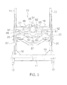
- FIG. 1 is an exploded perspective view of a new hydraulic puller device according to the present invention.
- FIG. 2 is a top, front perspective view of the present invention.
- FIG. 3 is a bottom, rear view of the present invention.
- FIG. 4 is a side elevational view of the present invention.
- FIGS. 1 through 4 a new hydraulic puller device embodying the principles and concepts of the present invention and generally designated by the reference numeral 10 will be described.
- the hydraulic puller device 10 generally comprises a mobile base assembly 11 - 26 , a jaw assembly 27 - 77 being mounted to the base assembly 11 - 26 and including a plurality of jaw members 27 , 31 , 35 , 39 , a press assembly 78 - 90 being mounted to the base assembly 11 - 26 for urging against an object to facilitate the removal of a press fitted work piece, and a control assembly 91 - 102 being in fluid communication with the base assembly 11 - 26 , the jaw assembly 27 - 77 and the press assembly 78 - 90 .
- the mobile base assembly 11 - 26 includes a base member 11 being conventionally mounted upon a set of wheels 12 and also includes vertically-extending masts 13 - 14 being spaced apart and being securely supported upon the base member 11 with braces 15 - 16 which are conventionally welded to the masts 14 - 14 and to the base member 11 .
- the support assembly 17 - 26 includes sleeves 17 - 18 being movably disposed upon and about the masts 13 - 14 and also includes planar support members 19 , 21 , 23 , 25 being conventionally attached to the sleeves 17 - 18 and extending between the masts 13 - 14 .
- the support members 19 , 21 , 23 , 25 include upper and lower support members 19 , 21 , 23 , 25 being vertically spaced apart.
- the upper and lower support members 19 , 21 , 23 , 25 have openings 20 , 22 , 24 , 26 being disposed therethrough.
- Each jaw member 27 , 31 , 35 , 39 has proximate and distal ends 28 , 29 , 32 , 33 , 36 , 37 , 40 , 41 and has at least a laterally-curved portion 103 - 106 .
- the proximate ends 28 , 32 , 36 , 40 of the jaw members 27 , 31 , 35 , 39 are pivotally mounted about vertical axes and conventionally connected to the support members 19 , 21 , 23 , 25 .
- Each of the jaw members 27 , 31 , 35 , 39 has a longitudinal flange 47 - 50 extending either upwardly or downwardly along at least a portion of an outer edge of each jaw member 27 , 31 , 35 , 39 .
- Each jaw member 27 , 31 , 35 , 39 has an arcuate work-piece engagement member 43 - 46 having a generally claw-like end and being pivotally mounted about a vertical axis and being conventionally attached with a bolt at the distal end 29 , 33 , 37 , 41 thereof for precise engagement to the work piece.
- the distal end 29 , 33 , 37 , 41 of each jaw member 27 , 31 , 35 , 39 has a longitudinal slot 30 , 34 , 38 , 42 for receiving at least a portion of a respective work-piece engagement member 43 - 46 .
- the jaw members 27 , 31 , 35 , 39 include a first pair of jaw members 27 , 31 with the jaw members 27 , 31 being horizontally opposed to one another.
- the jaw members 27 , 31 , 35 , 39 further include a second pair of jaw members 35 , 39 with the jaw members 35 , 39 thereof being horizontally opposed to one another and being vertically aligned with and spaced apart from the first pair of jaw members 27 , 31 .
- the jaw support assembly 51 - 77 includes a support frame 51 being movably disposed about and along the jaw members 27 , 31 , 35 , 39 .
- the support frame 51 includes upper and lower elongate guide support members 52 , 57 and jaw guide members 62 , 69 being horizontally adjustable relative to the upper and lower elongate guide support members 52 , 57 to adjust the horizontal positioning of the jaw members 27 , 31 , 35 , 39 , and the jaw guide members 62 , 69 are conventionally fastened to the upper and lower elongate guide support members 52 , 57 and are engagable to the longitudinal flanges 47 - 50 for moving the jaw members 27 , 31 , 35 , 39 inwardly and outwardly relative to one another.
- Each upper and lower elongate guide support member 52 , 57 has opposed ends 53 - 54 , 58 - 59 with slots 55 - 56 , 60 - 61 being disposed therein.
- Each jaw guide member 62 , 69 has a vertically-disposed elongate main portion 63 , 70 and a plurality of cross portions 64 - 66 , 71 - 73 extending generally perpendicular to the elongate main portion 63 , 70 and being spaced apart from one another and also having lengths which are shorter than the elongate main portion 63 , 70 .
- each jaw guide member 62 , 69 include an upper, middle and lower cross portions 64 - 66 , 71 - 73 .
- Each upper cross portion 64 , 71 is adjustably and conventionally fastened with bolts in a respective one of the slots 55 , 56 of the upper elongate guide support member 52 .
- Each lower cross portion 66 , 73 is adjustably and conventionally fastened with bolts in a respective one of the slots 60 , 61 of the lower elongate guide support member 57 .
- Each middle cross portion 65 , 72 is disposed between a respective pair of vertically-aligned the jaw members 27 , 31 , 35 , 39 .
- Each upper cross portion 64 , 71 has a slot 67 - 68 being disposed in a bottom thereof with the longitudinal flanges 47 - 48 of the first pair of jaw members 27 , 31 being received in the slots 67 - 68 of the upper cross portions 64 , 71 .
- Each middle cross portion 65 , 72 has a slot 74 , 75 being disposed in a bottom thereof with the longitudinal flanges 49 , 50 of the second pair of jaw members 35 , 39 being received in the slots 74 , 75 of the middle cross portions 65 , 72 .
- the press assembly 78 - 90 includes a housing 78 having walls and an opening disposed through one of the walls 81 with the housing 78 being disposed between the masts 13 - 14 , and also includes brackets 85 - 90 being conventionally attached and welded to the housing 78 and being securely and conventionally connected with bolts to the support members 19 , 21 , 23 , 25 , and further includes a press connector 83 being movably disposed in the housing 78 and through the opening of the housing 78 .
- the press assembly 78 - 90 also includes press adapters 84 being interchangeably and conventionally connected to the press connector 83 for urging against the object to facilitate removal of the press fitted work piece.
- the brackets 85 - 90 includes upper, middle and lower brackets 85 - 90 being conventionally attached and welded to the housing 78 and extending outwardly from opposite sides of the housing 78 .
- the control assembly 91 - 102 includes a first hydraulic cylinder 91 being conventionally mounted to the housing 78 and being engaged to the press connector 83 for actuating the press connector 83 and the press adapters 84 , and also includes second hydraulic cylinders 92 - 95 being conventionally connected to the support members 19 , 21 , 23 , 25 and to the support frame 51 via brackets 76 - 77 with fasteners such as bolts for actuating and moving the support frame 51 which engages and moves the jaw members 27 , 31 , 35 , 39 , and further includes vertically extending third hydraulic cylinders 96 - 97 being securely and conventionally mounted with bracket members upon the base member 11 proximate to the masts 13 - 14 for raising and lowering the jaw members 27 , 31 , 35 , 39 , and also includes a control unit 98 being conventionally mounted to the support assembly 17 - 26 and being in fluid communication with the hydraulic cylinders 91 - 97 via hoses 101 and having valves 99 for controlling hydraulic fluid
- the third hydraulic cylinders 96 - 97 are securely and conventionally attached to the support members 19 , 21 , 23 , 25 and extend through the openings 20 , 22 , 24 , 26 of the support members 19 , 21 , 23 , 25 for raising and lowering the jaw members 27 , 31 , 35 , 39 .
- the hydraulic assembly 91 - 102 includes a control switch 102 being in communication with the control unit 98 with wires conventionally interconnecting the control unit 98 to the control switch 102 for operating and controlling the hydraulic cylinders 91 - 97 .
- the hydraulic puller device 10 is positioned adjacent to the object and adjacent to the press fitted work piece to be removed from the object.
- the control switch 102 either the user actuates the third cylinders 96 - 97 with hydraulic pressure from the hydraulic pump 100 to raise and lower the jaw members 27 , 31 , 35 , 39 to horizontally position the jaw members 27 , 31 , 35 , 39 relative to the press fitted work piece, or if the jaw members 27 , 31 , 35 , 39 are already positioned correctly, the user actuates the second hydraulic cylinders 92 - 95 with hydraulic pressure from the hydraulic pump 100 to either spread the jaw members 27 , 31 , 35 , 39 apart with the jaw guide members 62 , 69 engaging the longitudinal flanges 47 - 50 so that the work-piece engagement members 43 - 46 can engage about the press fitted work piece or bring together the jaw members 27 , 31 , 35 , 39 with the jaw guide members 62 , 69 engaging the longitudinal flanges 47 - 50 to effectively engage the jaw members
- the jaw guide members 62 , 69 are able to move the jaw members 27 , 31 , 35 , 39 inwardly or outwardly relative to the horizontally-opposed jaw members 27 , 31 , 35 , 39 because of the laterally-curved portions 103 - 106 of the jaw members 27 , 31 , 35 , 39 .
- the press adapter 84 pushes on the object, the press fitted work piece is removed from the object because the jaw members 27 , 31 , 35 , 39 remain engaged about the press fitted work piece and the press adapter 84 pushes on the object and moves relative to the jaw members 27 , 31 , 35 , 39 .
Landscapes
- Engineering & Computer Science (AREA)
- Mechanical Engineering (AREA)
- Life Sciences & Earth Sciences (AREA)
- Geology (AREA)
- Mining & Mineral Resources (AREA)
- Physics & Mathematics (AREA)
- Environmental & Geological Engineering (AREA)
- Fluid Mechanics (AREA)
- General Life Sciences & Earth Sciences (AREA)
- Geochemistry & Mineralogy (AREA)
- Hand Tools For Fitting Together And Separating, Or Other Hand Tools (AREA)
Abstract
Description
Claims (15)
Priority Applications (1)
| Application Number | Priority Date | Filing Date | Title |
|---|---|---|---|
| US13/219,766 US8899133B1 (en) | 2011-08-29 | 2011-08-29 | Hydraulic puller device |
Applications Claiming Priority (1)
| Application Number | Priority Date | Filing Date | Title |
|---|---|---|---|
| US13/219,766 US8899133B1 (en) | 2011-08-29 | 2011-08-29 | Hydraulic puller device |
Publications (1)
| Publication Number | Publication Date |
|---|---|
| US8899133B1 true US8899133B1 (en) | 2014-12-02 |
Family
ID=51948253
Family Applications (1)
| Application Number | Title | Priority Date | Filing Date |
|---|---|---|---|
| US13/219,766 Active 2033-07-23 US8899133B1 (en) | 2011-08-29 | 2011-08-29 | Hydraulic puller device |
Country Status (1)
| Country | Link |
|---|---|
| US (1) | US8899133B1 (en) |
Cited By (3)
| Publication number | Priority date | Publication date | Assignee | Title |
|---|---|---|---|---|
| US20130255965A1 (en) * | 2012-03-29 | 2013-10-03 | Black Dog Industries Llc | Breakout Wrench Assemblies and Methods |
| US10435964B2 (en) * | 2016-11-07 | 2019-10-08 | Nabors Drilling Technologies Usa, Inc. | Modular gripperhead with effector for a racker system |
| US11506002B2 (en) | 2017-09-11 | 2022-11-22 | Nabors Drilling Technologies Usa, Inc. | Systems, devices, and methods to detect pipe with a gripperhead |
Citations (2)
| Publication number | Priority date | Publication date | Assignee | Title |
|---|---|---|---|---|
| US20050061112A1 (en) * | 2003-09-19 | 2005-03-24 | Weatherford Lamb, Inc. | Adapter frame for a power frame |
| US20090126536A1 (en) * | 2007-11-20 | 2009-05-21 | Frank's Casing Crew & Rental Tools, Inc. | Slippage Sensor and Method of Operating an Integrated Power Tong and Back-Up Tong |
-
2011
- 2011-08-29 US US13/219,766 patent/US8899133B1/en active Active
Patent Citations (2)
| Publication number | Priority date | Publication date | Assignee | Title |
|---|---|---|---|---|
| US20050061112A1 (en) * | 2003-09-19 | 2005-03-24 | Weatherford Lamb, Inc. | Adapter frame for a power frame |
| US20090126536A1 (en) * | 2007-11-20 | 2009-05-21 | Frank's Casing Crew & Rental Tools, Inc. | Slippage Sensor and Method of Operating an Integrated Power Tong and Back-Up Tong |
Cited By (4)
| Publication number | Priority date | Publication date | Assignee | Title |
|---|---|---|---|---|
| US20130255965A1 (en) * | 2012-03-29 | 2013-10-03 | Black Dog Industries Llc | Breakout Wrench Assemblies and Methods |
| US9447645B2 (en) * | 2012-03-29 | 2016-09-20 | Black Dog Industries Llc | Breakout wrench assemblies and methods |
| US10435964B2 (en) * | 2016-11-07 | 2019-10-08 | Nabors Drilling Technologies Usa, Inc. | Modular gripperhead with effector for a racker system |
| US11506002B2 (en) | 2017-09-11 | 2022-11-22 | Nabors Drilling Technologies Usa, Inc. | Systems, devices, and methods to detect pipe with a gripperhead |
Similar Documents
| Publication | Publication Date | Title |
|---|---|---|
| EP3546116B2 (en) | Device for tightening screw joints | |
| US8899133B1 (en) | Hydraulic puller device | |
| KR100929967B1 (en) | Pump Shaft Maintenance Work Table | |
| CN102252163B (en) | Automatic loading and unloading machine of cylinder valve | |
| CN202684499U (en) | Disposable assembly device of oil cylinder | |
| CN202643209U (en) | Combination type overhauling carrier | |
| CN103215955B (en) | Airborne hydraulic spiral pile driver | |
| CN205148268U (en) | Multi -functional maintenance platform | |
| CN204001643U (en) | A kind of indoor suspended ceiling hangs muscle erecting device | |
| CN110228225A (en) | A kind of interior high-pressure molding hydraulic press | |
| CN102198468A (en) | Mobile punch machine | |
| KR20150001693U (en) | Stand for cable drum | |
| CN201115869Y (en) | Horizontal punch-rivet machine | |
| CN205423497U (en) | Automatic hook lock structure | |
| CN203461744U (en) | Hydraulic sling cart | |
| CN218192157U (en) | Automatic throat machine of feeding | |
| CN220127356U (en) | Pipe fitting processing device | |
| CN102126232B (en) | Jig saw | |
| CN110405735A (en) | A kind of intelligent robot grabbing device | |
| CN213411815U (en) | Device for screwing nut in narrow space | |
| CN104235583B (en) | A kind of Main Drive of Rolling Mill axial cross bearing packet recharging oil device | |
| CN209207395U (en) | One kind is mostly used hydraulic to unload chain device | |
| CN209491186U (en) | Quickly adjust guide and guards | |
| CN208992421U (en) | A kind of steel pipe inner wall workpiece polishing mechanism | |
| CN201052428Y (en) | Filter fan assembly filter cloth strainer |
Legal Events
| Date | Code | Title | Description |
|---|---|---|---|
| STCF | Information on status: patent grant |
Free format text: PATENTED CASE |
|
| FEPP | Fee payment procedure |
Free format text: MAINTENANCE FEE REMINDER MAILED (ORIGINAL EVENT CODE: REM.) |
|
| FEPP | Fee payment procedure |
Free format text: SURCHARGE FOR LATE PAYMENT, SMALL ENTITY (ORIGINAL EVENT CODE: M2554); ENTITY STATUS OF PATENT OWNER: SMALL ENTITY |
|
| MAFP | Maintenance fee payment |
Free format text: PAYMENT OF MAINTENANCE FEE, 4TH YR, SMALL ENTITY (ORIGINAL EVENT CODE: M2551); ENTITY STATUS OF PATENT OWNER: SMALL ENTITY Year of fee payment: 4 |
|
| AS | Assignment |
Owner name: POSILOCK PULLER, INC., NORTH DAKOTA Free format text: ASSIGNMENT OF ASSIGNORS INTEREST;ASSIGNOR:SOMERVILLE, DEAN S.;REEL/FRAME:053340/0409 Effective date: 20200725 |
|
| AS | Assignment |
Owner name: SPX FLOW US, LLC, NORTH CAROLINA Free format text: ASSIGNMENT OF ASSIGNORS INTEREST;ASSIGNOR:POSILOCK PULLER, INC.;REEL/FRAME:054046/0935 Effective date: 20200731 |
|
| AS | Assignment |
Owner name: BANK OF AMERICA, N.A., AS ADMINISTRATIVE AGENT, TEXAS Free format text: NOTICE OF GRANT OF SECURITY INTEREST IN PATENTS;ASSIGNOR:SPX FLOW US, LLC;REEL/FRAME:057086/0053 Effective date: 20210803 |
|
| AS | Assignment |
Owner name: CITIBANK, N.A., NEW YORK Free format text: SECURITY INTEREST;ASSIGNORS:PHILADELPHIA MIXING SOLUTIONS LLC;SPX FLOW TECHNOLOGY USA, INC.;SPX FLOW, INC.;AND OTHERS;REEL/FRAME:059619/0158 Effective date: 20220405 |
|
| MAFP | Maintenance fee payment |
Free format text: PAYMENT OF MAINTENANCE FEE, 8TH YR, SMALL ENTITY (ORIGINAL EVENT CODE: M2552); ENTITY STATUS OF PATENT OWNER: SMALL ENTITY Year of fee payment: 8 |
|
| AS | Assignment |
Owner name: HYDRAULIC TECHNOLOGIES USA LLC, ILLINOIS Free format text: ASSIGNMENT OF ASSIGNORS INTEREST;ASSIGNOR:SPX FLOW US LLC;REEL/FRAME:067227/0874 Effective date: 20240423 |
|
| AS | Assignment |
Owner name: SPX FLOW US, LLC, NORTH CAROLINA Free format text: RELEASE OF SECURITY INTEREST RECORDED AT REEL/FRAME 057086/0053;ASSIGNOR:BANK OF AMERICA, N.A.;REEL/FRAME:067528/0852 Effective date: 20220405 |
|
| AS | Assignment |
Owner name: ANTARES CAPITAL LP, AS AGENT, ILLINOIS Free format text: SECURITY INTEREST;ASSIGNOR:HYDRAULIC TECHNOLOGIES USA LLC;REEL/FRAME:067595/0711 Effective date: 20240603 Owner name: HYDRAULIC TECHNOLOGIES USA LLC, ILLINOIS Free format text: TERMINATION AND RELEASE OF SECURITY INTEREST IN INTELLECTUAL PROPERTY;ASSIGNOR:CITIBANK, N.A.;REEL/FRAME:067607/0936 Effective date: 20240603 |
|
| AS | Assignment |
Owner name: HYDRAULIC TECHNOLOGIES USA LLC, ILLINOIS Free format text: RELEASE BY SECURED PARTY;ASSIGNOR:CITIBANK, N.A.;REEL/FRAME:067629/0831 Effective date: 20240603 |