CROSS REFERENCE TO RELATED APPLICATION
This application claims priority to Taiwan Patent Application No. 101146021 filed on Dec. 7, 2012.
BACKGROUND OF THE INVENTION
The present invention relates to the field of touch devices, and more particularly, to a detecting method for a touch device.
Detecting methods for a touch device have been disclosed in the prior art. According to the prior art detecting methods, whether there is an object in contact with a touch panel of the touch device is determined by comparing all sensed values of a base frame that are pre-stored in a memory are compared with all sensed values of a frame that is read at a subsequent time point. However, if there is any flaw in the pre-stored base frame, the comparison result may lead to malfunction of the touch device.
It may therefore desirable to have a detecting method for a touch device to overcome the aforementioned defects.
BRIEF SUMMARY OF THE INVENTION
Examples of the present invention may provide a detecting method for a touch device, which comprises steps of: reading all sensed values of a frame associated with the touch device; computing a difference between a maximum sensed value and a minimum sensed value of all the sensed values of the frame; comparing the difference with a base value so as to generate a comparison result and executing a corresponding operation based on the comparison result.
Some examples of the present invention may provide a detecting method for a touch device, which comprises steps of: defining a plurality of continuous time points; reading, at each of the plurality of continuous time points, all sensed values of a frame associated with the touch device corresponding to the time point; computing a difference between a maximum sensed value and a minimum sensed value of all the sensed values of a frame read at each of the time points; comparing the difference computed at each of the time points with a base value so as to generate a comparison result and executing a corresponding operation based on the comparison result.
Additional features and advantages of the present invention will be set forth in part in the description which follows, and in part will be obvious from the description, or may be learned by practice of the invention. The features and advantages of the invention will be realized and attained by means of the elements and combinations particularly pointed out in the appended claims.
It is to be understood that both the foregoing general description and the following detailed description are exemplary and explanatory only and are not restrictive of the invention, as claimed.
BRIEF DESCRIPTION OF THE SEVERAL VIEWS OF THE DRAWINGS
The foregoing summary, as well as the following detailed description of the invention, will be better understood when read in conjunction with the appended drawings. For the purpose of illustrating the invention, there are shown in the drawings examples which are presently preferred. It should be understood, however, that the invention is not limited to the precise arrangements and instrumentalities shown.
In the drawings:
FIG. 1 is a schematic view of a frame associated with a touch device;
FIG. 2 is a schematic view illustrating the computation of the difference associated with the frame;
FIG. 3 is a schematic view of a detecting method for a touch device according to an embodiment of the present invention;
FIG. 4 is a flowchart of the detecting method shown in FIG. 3;
FIG. 5 is a schematic view of a detecting method for a touch device according to another embodiment of the present invention;
FIG. 6 is a flowchart of the detecting method shown in FIG. 5;
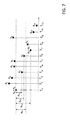
FIG. 7 is a schematic view of a detecting method for a touch device according to yet another embodiment of the present invention;
FIG. 8 is a flowchart of the detecting method shown in FIG. 7; and
FIG. 9 to FIG. 11 showing the variants of the embodiments shown in FIG. 3 to FIG. 8.
DETAILED DESCRIPTION OF THE INVENTION
Reference will now be made in detail to the present examples of the invention, examples of which are illustrated in the accompanying drawings. Wherever possible, the same reference numbers will be used throughout the drawings to refer to the same or like parts.
FIG. 1 is a schematic view of a frame associated with a touch device. As shown in FIG. 1, a touch panel 11 of the touch device 10 may include a plurality of sensing lines arranged in rows and columns, and a plurality of sensing points P are formed at intersections of the rows and the columns of the sensing lines. In this embodiment, the touch device 10 reads sensed value of each of the sensing points P on the touch device 10 by mutual-capacitance scanning and takes the sensed values as a frame F; however, this is only illustrated as an example but is not to limit the present invention. In another embodiment of the present invention, the touch device 10 may also read sensed values of all the sensing lines by self-capacitance scanning and take the sensed values as the frame F.
FIG. 2 is a schematic view illustrating the computation of the difference associated with the frame. The touch device 10 reads the frame F at each time point (including the power-on time point T0) after being powered on. The frame (referred to as “the initial frame F0” in the following description) read by the touch device 10 at the power-on time point T0 is stored in a memory and is used as a base frame FB. Moreover, the touch device 10 includes a difference between a maximum sensed value Cmax, B and a minimum sensed value Cmin, B of all the sensed values of the base frame FB, and sets the difference as a base value ΔB. For example, as shown in FIG. 3, if a user's palm contacts a lower left region of the touch panel 11 of the touch device 10 when the touch device 10 is powered on, sensed values C0, 0, C0, 1, . . . C3, 2, C3, 3 of the sensing points corresponding to the lower left region of the touch panel will be smaller than sensed values of sensing points corresponding to other regions of the touch panel. The maximum sensed value Cmax, B of the base frame FB may be, for example, C9, 6, and the minimum sensed value Cmin, B of the base frame FB may be, for example, C1, 1, and the base value ΔB is (C9, 6−C1, 1) in this example.
After being powered on, the touch device 10 reads sensed values corresponding to sensing points of a frame Fn at each time point Tn, computes a difference Δn between a maximum sensed value Cmax, n and a minimum sensed value Cmin, n of the sensed values corresponding to the sensing points of the frame Fn, compares the difference Δn with the base value ΔB to generate a comparison result, and executes an operation associated with the touch device 10 based on the comparison result, as will be described in detail below.
FIG. 3 is a schematic view of a detecting method for a touch device according to an embodiment of the present invention. As shown in FIG. 3, the touch device 10 computes the difference Δn between the maximum sensed value Cmax, n and the minimum sensed value Cmin, n at each time point Tn. For example, the touch device 10 computes a difference Δ1 at a time point T1 and computes a difference Δ2 at a time point T2, and so on. The touch device 10 computes a difference Δ10 at a time point T10.
At the time point T1, the touch device 10 compares the computed difference Δ1 with the base value ΔB. In this embodiment, since the difference Δ1 is greater than the base value ΔB, the base value ΔB and the base frame FB is not updated; that is, the base value ΔB is retained as the difference Δ0 and the base frame FB is retained as the initial frame F0.
Subsequently, at the next time point T2, the touch device 10 compares the computed difference Δ2 with the base value ΔB. In this embodiment, since the difference Δ2 is greater than the base value ΔB, the base value ΔB and the base frame FB is still not updated; that is, the base value ΔB is still retained as the difference Δ0, and the base frame FB is still retained as the initial frame F0.
Subsequently, at the next time point T3, the touch device 10 compares the computed difference Δ3 with the base value ΔB. At this point, since the difference Δ3 is smaller than the base value ΔB, the touch device 10 updates the base value ΔB and the base frame FB. The base value ΔB is updated to be the difference Δ3; and the base frame FB is updated to be a frame F3 read at the time point T3.
As the above embodiment, the touch device 10 compares the differences Δ4, Δ5 and Δ6, which are computed at the subsequent time points T4, T5 and T6 respectively, with the updated base value ΔB (ΔB=Δ3). Since the difference Δ6 is smaller than the updated base value ΔB, the base value ΔB is further updated, and the further updated base value ΔB is equal to the difference Δ6. Meanwhile, the base frame FB is further updated, and the further updated base frame FB is a frame F6 read at the time point T6.
According to the above embodiment, since the difference Δ7 computed at the subsequent time point T7 is smaller than the further updated base value ΔB, the base value ΔB is further updated to be the difference Δ7. Meanwhile, the base frame FB is further updated to be a frame F7 read at the time point T7, and so on. At the time point T10, the base value ΔB is further updated to be the difference Δ10, and the base frame FB is further updated to be a frame F10 read at the time point T10.
According to the above embodiment, the base value ΔB is updated to be a smaller value successively. The smaller the base value ΔB, the more uniformly all the sensed values of the corresponding base frame FB are distributed, which directs to a condition that no object is sensed when being in contact with the touch panel 11 with a smaller sensed value. Therefore, as the base value ΔB decreases successively, the corresponding base frame FB becomes more flawless.
In other words, the ideal base frame FB corresponds to sensed values of the sensing points which are not affected, that directs to a condition that no object is in contact with the touch panel 11. In such condition, the sensed values of the sensing points shall be approximate values with small differences therebetween. However, as there is an object in contact with the touch panel 11, the sensed values of sensing points affected by the object will vary greatly. Therefore, the difference Δn between the maximum sensed value Cmax, n and the minimum sensed value Cmin, n of the sensing points of the same frame F will be greater than the difference (i.e., the base value ΔB) of the ideal base frame FB. Therefore, by comparing the difference Δn between the maximum sensed value Cmax, n and the minimum sensed value Cmin, n of each frame F, the present invention can determine whether to update the base frame FB and the base value ΔB. In this way, the base frame FB can be successively updated as a frame with a smaller difference so that the updated base frame FB is close to the ideal frame FB.
Thus, even if an object (e.g., the palm of the user) accidentally makes contact with the touch panel 11 when the touch device 10 is powered on, and given that the frame F0 read at the power-on time point T0, which is affected by the object, is used as the base frame FB, the affected base frame FB can still be updated as a more ideal base frame by means of the updating mechanism of the present invention.
A flowchart of the aforementioned embodiment is as shown in FIG. 4
FIG. 5 is a schematic view of a detecting method for a touch device according to another embodiment of the present invention. In this embodiment of the present invention, the touch device 10 compares the difference Δn computed at the subsequent time point Tn with a product of the base value ΔB multiplied by a predetermined scaling factor R. If the difference Δn is smaller than the product of the base value ΔB multiplied by the predetermined scaling factor R, the base value ΔB is updated to be the difference Δn, and the base frame FB is updated to be a frame Fn read at the time point Tn. Otherwise, the base value ΔB and the base frame FB are kept unchanged. In this embodiment, the predetermined scaling factor R is smaller than or equal to 1.
Furthermore, as shown in FIG. 5, the difference Δ0 computed at the power-on time point T0 is set as the base value ΔB and the frame F0 read at the power-on time point T0 is set to be the base frame FB. Moreover, the predetermined scaling factor R is set as 50% (but is not limited thereto), and the difference Δn computed at the subsequent time point Tn is compared with (ΔB×50%).
Since the differences Δ1 to Δ6 computed at the subsequent time points T1 to T6 are all greater than (ΔB×50%), the base value ΔB and the base frame FB are not updated.
Thereafter, since the difference Δ7 computed at the time point T7 is smaller than (ΔB×50%), the base value ΔB is updated to be the difference Δ7. Meanwhile, the base frame FB is updated to be a frame F7 read at the time point T7.
Thereafter, the differences Δ8 to Δ11 computed at the subsequent time points T8 to T11 are compared with (ΔB×50%) (wherein the base value ΔB has been updated to be the difference Δ7). Since the difference Δ11 computed at the time point T11 is smaller than (ΔB×50%), the base value ΔB is further updated to be the difference Δ11. Meanwhile, the base frame FB is further updated to be a frame F11 read at the time point T11.
A flowchart of the aforementioned embodiment is as shown in FIG. 6.
FIG. 7 is a schematic view of a detecting method for a touch device according to another embodiment of the present invention. In this embodiment of the present invention, the touch device 10 compares the difference Δn computed at the subsequent time point Tn with the base value ΔB. If the difference Δn is smaller than the base value ΔB, and if an absolute value |Δn, B| of a difference value Δn, B between the difference Δn and the base value ΔB is greater than a predetermined threshold ΔTH (wherein the predetermined threshold ΔTH is a positive value), the base value ΔB is updated to be the difference Δn, and the base frame FB is updated to be a frame Fn read at the subsequent time point Tn. Otherwise, the base value ΔB and the base frame FB are kept unchanged.
Furthermore, as shown in FIG. 7, the difference Δ0 computed at the power-on time point T0 is set to be the base value ΔB, and the frame F0 read at the power-on time point T0 is set to be the base frame FB. Since the differences Δ1 and Δ2 computed at the subsequent time points T1 and T2 respectively are greater than the base value ΔB, the base value ΔB and the base frame FB are kept unchanged.
The difference Δ3 computed at the subsequent time point T3 is smaller than the base value ΔB and the absolute value |Δ3, B| of the difference value Δ3, B between the difference Δ3 and the base value ΔB is smaller than the predetermined threshold ΔTH, the base value ΔB and the base frame FB are still kept unchanged.
Next, since the differences Δ4 and Δ5 computed at the subsequent time points T4 and T5 respectively are greater than the base value ΔB, the base value ΔB and the base frame FB are kept unchanged. Thereafter, the difference Δ6 computed at the subsequent time point T6 is smaller than the base value ΔB and the absolute value |Δ6, B| of the difference value Δ6, 8 between the difference Δ6 and the base value ΔB is still smaller than the predetermined threshold ΔTH, the base value ΔB and the base frame FB are still kept unchanged.
Thereafter, the difference Δ7 computed at the subsequent time point T7 is smaller than the base value ΔB and the absolute value |Δ7, B| of the difference value Δ7, B between the difference Δ7 and the base value ΔB is greater than the predetermined threshold ΔTH, the base value ΔB is updated to be the difference Δ7, and the base frame FB is updated to be a frame F7 read at the time point T7.
A flowchart of the aforementioned embodiment is as shown in FIG. 8.
On the other hand, in the variants of the embodiments described above by reference to FIG. 3 to FIG. 8, the base frame FB is not limited to the frame F0 read by the touch device 10 at the power-on time point T0; instead, the base frame FB may also be a default frame FDef pre-stored in a programmable read only memory (PROM). Moreover, a difference ΔDef between a maximum value and a minimum value of all values of the default frame FDef is set to be the base value ΔB. Flowcharts of the aforementioned variants are shown in FIG. 9 to FIG. 11 respectively.
Furthermore, in the embodiment described above with reference to FIG. 3 to FIG. 4, if the difference Δn computed at the subsequent time point Tn is greater than the base value ΔB (the base value ΔB may be the difference Δ0 between the maximum sensed value and the minimum sensed value of the initial frame F0, or the difference ΔDef between the maximum value and the minimum value of the default frame FDef), the touch device 10 determines that there is an object in contact with the touch panel 11. Otherwise, if the difference Δn is smaller than the base value ΔB, the touch device 10 determines that there is no object in contact with the touch panel 11.
In another embodiment, if the difference Δn is greater than the base value ΔB (which represents that there is an object in contact with the touch panel 11; e.g., the user places his/her finger on the touch panel 11), then the touch device 10 will wake up an internal processor thereof and deactivate a sleeping mode of the processor.
It will be appreciated by those skilled in the art that changes could be made to the examples described above without departing from the broad inventive concept thereof. It is understood, therefore, that this invention is not limited to the particular examples disclosed, but it is intended to cover modifications within the spirit and scope of the present invention as defined by the appended claims.
Further, in describing representative examples of the present invention, the specification may have presented the method and/or process of the present invention as a particular sequence of steps. However, to the extent that the method or process does not rely on the particular order of steps set forth herein, the method or process should not be limited to the particular sequence of steps described. As one of ordinary skill in the art would appreciate, other sequences of steps may be possible. Therefore, the particular order of the steps set forth in the specification should not be construed as limitations on the claims. In addition, the claims directed to the method and/or process of the present invention should not be limited to the performance of their steps in the order written, and one skilled in the art can readily appreciate that the sequences may be varied and still remain within the spirit and scope of the present invention.