US8896226B2 - Constant-power power supply apparatus and method of supplying constant-power power - Google Patents
Constant-power power supply apparatus and method of supplying constant-power power Download PDFInfo
- Publication number
- US8896226B2 US8896226B2 US14/165,182 US201414165182A US8896226B2 US 8896226 B2 US8896226 B2 US 8896226B2 US 201414165182 A US201414165182 A US 201414165182A US 8896226 B2 US8896226 B2 US 8896226B2
- Authority
- US
- United States
- Prior art keywords
- voltage
- working
- power
- current
- loading
- Prior art date
- Legal status (The legal status is an assumption and is not a legal conclusion. Google has not performed a legal analysis and makes no representation as to the accuracy of the status listed.)
- Active
Links
Images


Classifications
-
- H—ELECTRICITY
- H05—ELECTRIC TECHNIQUES NOT OTHERWISE PROVIDED FOR
- H05B—ELECTRIC HEATING; ELECTRIC LIGHT SOURCES NOT OTHERWISE PROVIDED FOR; CIRCUIT ARRANGEMENTS FOR ELECTRIC LIGHT SOURCES, IN GENERAL
- H05B45/00—Circuit arrangements for operating light-emitting diodes [LED]
-
- H—ELECTRICITY
- H02—GENERATION; CONVERSION OR DISTRIBUTION OF ELECTRIC POWER
- H02M—APPARATUS FOR CONVERSION BETWEEN AC AND AC, BETWEEN AC AND DC, OR BETWEEN DC AND DC, AND FOR USE WITH MAINS OR SIMILAR POWER SUPPLY SYSTEMS; CONVERSION OF DC OR AC INPUT POWER INTO SURGE OUTPUT POWER; CONTROL OR REGULATION THEREOF
- H02M3/00—Conversion of dc power input into dc power output
- H02M3/02—Conversion of dc power input into dc power output without intermediate conversion into ac
- H02M3/04—Conversion of dc power input into dc power output without intermediate conversion into ac by static converters
-
- H05B33/08—
-
- H05B33/0845—
-
- H—ELECTRICITY
- H05—ELECTRIC TECHNIQUES NOT OTHERWISE PROVIDED FOR
- H05B—ELECTRIC HEATING; ELECTRIC LIGHT SOURCES NOT OTHERWISE PROVIDED FOR; CIRCUIT ARRANGEMENTS FOR ELECTRIC LIGHT SOURCES, IN GENERAL
- H05B45/00—Circuit arrangements for operating light-emitting diodes [LED]
- H05B45/10—Controlling the intensity of the light
Definitions
- the present invention relates generally to an apparatus of driving loading, and more particularly to a constant-power power supply apparatus and a method of supplying constant-power power.
- a constant-power power supply apparatus is used to supplies a specific loading, such as LED (light emitting diode) chip or rechargeable battery, with a constant-power electric power.
- the conventional constant-power power supply apparatus provides a constant working voltage and a constant working current to the loading only, so that the devices driven by different working voltages and/or working currents need the constant-power power supply apparatus with different specs.
- the working voltages and working currents for 28 W LED chips includes 80V/350 mA, 56V/500 mA, and 40V/700 mA, and each LED chip needs a specific constant-power power supply apparatus. Therefore, for a manufacturer of LED chips, he has to make a variety of LED chips as well as a variety of constant-power power supply apparatus so that the conventional LED chips are very expensive. In conclusion, the conventional constant-power power supply apparatus still needs to be improved.
- the primary objective of the present invention is to provide a constant-power power supply apparatus and a method of supplying constant-power power, which is controllable to provide different voltages and currents under a constant power.
- the present invention provides a method of supplying a loading with an electric power within a predetermined range of a default power, wherein at least two reference voltages are predetermined, and each two neighboring reference voltages are defined to have a voltage section therebetween, and each voltage section has a slope parameter accordingly; the method includes the steps of: detecting a working voltage of the electric power supplied to the loading; obtaining the slope parameter of the voltage section in which the working voltage falls; and generating a working current according to the working voltage and the obtained slope parameter, wherein a product of the working current and the working voltage is in the predetermined range of the default power.
- the present invention further provides a power supply apparatus for receiving power from a power source and supplying a loading with an electric power within a predetermined range of a default power, includes a driving unit, a voltage sensing unit, and a feedback control unit, wherein the driving unit is for receiving the power from the power source and supplying the loading with a working voltage and a working current; the voltage sensing unit is electrically connected to the driving unit to detect the working voltage; the feedback control unit is electrically connected to the voltage sensing unit and the driving unit, wherein the feedback control unit keeps at least two reference voltages, and each two neighboring reference voltages are defined to have a voltage section therebetween, and each voltage section has a slope parameter accordingly; wherein the feedback control unit receives the working voltage sensed by the voltage sensing unit, and finds the voltage section in which the working voltage falls to obtain the slope parameter of the voltage section, and then sends a current signal, which is according to the working voltage and the obtained slope parameter, to the driving unit to command the driving unit to change the working current accordingly, wherein
- the aforementioned apparatus and method could be applied for loadings which require the same power but different working voltage and/or working current, since the power provided is remained in the predetermined range of the default power. Therefore, the inconvenience of the conventional constant-power power supply apparatus that it could be only compatible with single working voltage and single working current is effectively improved.
- FIG. 1 is a block diagram of the constant-power power supply apparatus of a preferred embodiment of the present invention, which is applied in a LED illumination system;
- FIG. 2A is a diagram of the preferred embodiment of the present invention, showing the relation of the working voltage and the working current;
- FIG. 2B is an enlarged view of FIG. 2A , showing the voltage section between two neighboring reference voltages.
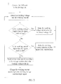
- FIG. 3 is a flow chart of the method of the preferred embodiment of the present invention.
- FIG. 1 shows an illumination system with a constant-power power supply apparatus of a preferred embodiment of the present invention.
- the constant-power power supply apparatus is respectively connected to a power source 10 and a loading, which is a LED chip 20 in the preferred embodiment.
- the constant-power power supply apparatus includes a driving unit 30 and a constant-power modulation module 40 .
- the driving unit 30 is electrically connected to the power source 10 and the LED chip 20 respectively to receive power from the power source 10 and supply a working voltage and a working current to the LED chip 20 .
- the driving unit 30 is controllable to change a value of the working voltage and a value of the working current.
- the driving unit 30 could be designed based on PWM circuit, half-bridge circuit, or buck boost circuit.
- the constant-power modulation module 40 has a voltage sensing unit 42 , a current sensing unit 44 , and a feedback control unit 46 .
- the voltage sensing unit 42 and the current sensing unit 44 are electrically connected to the driving unit 30 to detect the value of the working voltage and the working current supplied to the LED chip 20 respectively.
- the feedback control unit 46 has a comparator 462 and a signal generator 464 .
- the comparator 462 is electrically connected to the voltage sensing unit 42
- the signal generator 464 is electrically connected to the driving unit 30 .
- the comparator 462 keeps four reference voltages V 1 , V 2 , V 3 , and V 4 , each of which has a reference current corresponding to a value of the working current.
- Each two neighboring reference voltages are defined to have a voltage section S therebetween, and there is a straight line defined in each voltage section S to connect two corresponding reference voltages.
- the straight lines approach the real relation curve C of the ideal working voltages versus ideal working currents, wherein at any point on the relation curve C, a product of the working voltage and the working current is the same, and the product is a default power.
- the highest reference voltage V 1 is defined as an upper limit voltage Vmax
- the lowest reference voltage V 4 is a lower limit voltage Vmin
- the corresponding reference currents are upper limit current Imax and lower limit current Imax respectively.
- Each straight light has a slope, wherein absolute values the slopes of the straight lines decrease from the voltage section S between the reference voltages V 1 and V 2 to the voltage section S between the reference voltages V 3 and V 4 .
- the absolute value of the slope of the straight line in the voltage section S between the reference voltages V 1 and V 2 is the highest, and the absolute value of the slope of the straight line in the voltage section S between the reference voltages V 3 and V 4 is the lowest.
- the comparator 462 keeps slope parameters corresponding to each slope of each straight line in each voltage sections S respectively. In this way, the comparator 462 sends out a slope signal according to the slope parameters.
- the signal generator 464 receives the slope signal, and then generates a current signal according to the received slope signal and the working voltage.
- the driving unit 30 receives the current signal to change the current supplied to the LED chip 20 accordingly.
- the comparator 462 further generates a voltage limitation signal and a current limitation signal.
- the signal generator 464 receives these two signals to command the driving unit 30 to limit the working voltage and the working current supplied to the LED chip 20 no higher than a predetermined voltage and current to protect the LED chip 20 from being burned by high voltage or high current.
- the present invention further provides a method of supplying a constant-power power, as shown in FIG. 3 , and the method includes the following steps:
- the signal generator 464 compare the working voltage with the upper limit voltage Vmax, and then send the voltage limitation signal to the signal generator 464 if the working voltage is higher than the upper limit voltage Vmax or go to the step D otherwise.
- the signal generator 464 When the working voltage is higher than the upper limit voltage Vmax, the signal generator 464 generates an upper limit voltage signal, and send it to the driving unit 30 to make the working voltage supplied to the LED chip 20 identical to the reference voltage V 1 , and then go back to the step B.
- the comparator 462 Compare the working current with the upper limit current by the comparator 462 , and then send the current limitation signal to the signal generator 464 if the working current is higher than the upper limit current Imax or go to the step E otherwise.
- the signal generator 464 When the working current is higher than the upper limit current Imax, the signal generator 464 generates an upper limit current signal, and send it to the driving unit 30 to make the working current supplied to the LED chip 20 identical to the upper limit current Imax, and then go back to the step B.
- the signal generator 464 generates the current signal according to the working voltage and the slope signal to command the driving unit 30 to supply the LED chip 20 with a predetermined current.
- the power (the product of the working voltage and the working current) of the electric power supplied to the LED chip 20 is within a predetermined range of the default power.
- the present invention provides a plurality of the voltage sections, and obtains a slope of a straight line, which approaches the ideal relation curve for constant power, in each voltage section to get the corresponding working current by the detected working voltage and the slope of the voltage section which the working voltage falls in.
- the predetermined range of the default power is in a range between 90% and 110% of the default power (i.e., the default power ⁇ 10%).
- the predetermined range will be between 25.2 W and 30.8 W.
- step F Repeat the steps from the step B to the step E to keep supplying the LED chip 20 with an electric power of constant power.
- the present invention is applicable for the LED chips with the same working voltage and working current, and also for the LED chips with different working voltage and/or working current.
- one of the power supply apparatus of the present invention could be incorporated in different LED chips.
- the power supply apparatus of the present invention could be applied to other electric or electronic devices, such as rechargeable batteries, which need a constant-power electric power as well.
- the present invention defines several voltage sections, and approaches the ideal constant-power curve by connecting the straight lines in each voltage section. If the working voltage of the loading changes, which means it shifts to another voltage section, the present invention would still get the corresponding current to supply the electric power within the predetermined range of the default power. It is easy to understand that if number of the voltage sections increases, the connected straight lines from each voltage sections will be closer to the ideal constant-power curve.
Abstract
Description
Claims (16)
Applications Claiming Priority (6)
| Application Number | Priority Date | Filing Date | Title |
|---|---|---|---|
| TW102105249A TWI522004B (en) | 2013-02-08 | 2013-02-08 | Variable power of the light-emitting diode lighting device and set the power output control method |
| TW102203042 | 2013-02-08 | ||
| TW102105249 | 2013-02-08 | ||
| TW102105249A | 2013-02-08 | ||
| TW102203042U TWM458051U (en) | 2013-02-08 | 2013-02-08 | Constant power supply device |
| TW102203042U | 2013-02-08 |
Publications (2)
| Publication Number | Publication Date |
|---|---|
| US20140225525A1 US20140225525A1 (en) | 2014-08-14 |
| US8896226B2 true US8896226B2 (en) | 2014-11-25 |
Family
ID=50071414
Family Applications (1)
| Application Number | Title | Priority Date | Filing Date |
|---|---|---|---|
| US14/165,182 Active US8896226B2 (en) | 2013-02-08 | 2014-01-27 | Constant-power power supply apparatus and method of supplying constant-power power |
Country Status (2)
| Country | Link |
|---|---|
| US (1) | US8896226B2 (en) |
| EP (1) | EP2765829A3 (en) |
Families Citing this family (5)
| Publication number | Priority date | Publication date | Assignee | Title |
|---|---|---|---|---|
| JP6145788B2 (en) * | 2013-09-13 | 2017-06-14 | パナソニックIpマネジメント株式会社 | Illumination light source and illumination device |
| JP6145821B2 (en) | 2013-09-13 | 2017-06-14 | パナソニックIpマネジメント株式会社 | Illumination light source and illumination device |
| KR102293330B1 (en) * | 2013-11-11 | 2021-08-25 | 주식회사 솔루엠 | Led control device |
| MX2018006574A (en) * | 2015-12-08 | 2018-08-01 | Eaton Intelligent Power Ltd | Constant power supply for thermo-electric cells. |
| WO2019084899A1 (en) * | 2017-11-03 | 2019-05-09 | Dialog Semiconductor (Uk) Limited | Switch driver |
Citations (3)
| Publication number | Priority date | Publication date | Assignee | Title |
|---|---|---|---|---|
| US8350497B2 (en) * | 2009-11-06 | 2013-01-08 | Neofocal Systems, Inc. | Method and apparatus for outputting light in a LED-based lighting system |
| US8564222B2 (en) * | 2011-08-09 | 2013-10-22 | Shenzhen Tention Optoectronic Co., Ltd. | Lighting device controlling circuit module |
| US8653752B2 (en) * | 2011-04-14 | 2014-02-18 | Nichia Corporation | Light-emitting diode driving apparatus for suppressing harmonic components |
Family Cites Families (5)
| Publication number | Priority date | Publication date | Assignee | Title |
|---|---|---|---|---|
| JP4050474B2 (en) * | 2001-02-26 | 2008-02-20 | 株式会社小糸製作所 | Discharge lamp lighting circuit |
| DE102006056057A1 (en) * | 2006-02-28 | 2007-09-06 | Samsung Electro - Mechanics Co., Ltd., Suwon | Drive device for a colored LED backlight |
| US8174197B2 (en) * | 2009-04-09 | 2012-05-08 | Ge Lighting Solutions Llc | Power control circuit and method |
| US8779746B2 (en) * | 2011-04-29 | 2014-07-15 | Texas Instruments Incorporated | Methods and apparatus for constant power/current control for switch-mode power converters |
| CN102523663B (en) * | 2012-01-06 | 2014-05-07 | 广州市隆都电子有限公司 | Constant-power LED drive circuit |
-
2014
- 2014-01-27 US US14/165,182 patent/US8896226B2/en active Active
- 2014-01-28 EP EP14152836.4A patent/EP2765829A3/en not_active Withdrawn
Patent Citations (3)
| Publication number | Priority date | Publication date | Assignee | Title |
|---|---|---|---|---|
| US8350497B2 (en) * | 2009-11-06 | 2013-01-08 | Neofocal Systems, Inc. | Method and apparatus for outputting light in a LED-based lighting system |
| US8653752B2 (en) * | 2011-04-14 | 2014-02-18 | Nichia Corporation | Light-emitting diode driving apparatus for suppressing harmonic components |
| US8564222B2 (en) * | 2011-08-09 | 2013-10-22 | Shenzhen Tention Optoectronic Co., Ltd. | Lighting device controlling circuit module |
Also Published As
| Publication number | Publication date |
|---|---|
| US20140225525A1 (en) | 2014-08-14 |
| EP2765829A3 (en) | 2015-10-21 |
| EP2765829A2 (en) | 2014-08-13 |
Similar Documents
| Publication | Publication Date | Title |
|---|---|---|
| US8896226B2 (en) | Constant-power power supply apparatus and method of supplying constant-power power | |
| KR101677730B1 (en) | Led light emitting device | |
| CN101960922B (en) | Supply unit and ligthing paraphernalia | |
| US8144111B2 (en) | Light emitting diode driving circuit having voltage detection | |
| US8648847B2 (en) | LED driving apparatus which controls based on LED state | |
| US9131579B2 (en) | Driving apparatus for LED chips of different specifications | |
| US9167654B2 (en) | Solid light source lighting device, illumination apparatus, and illumination system | |
| US9445478B2 (en) | Light-emitting element lighting device, light-emitting module, illuminating apparatus, and light-emitting element lighting method | |
| CN103987147B (en) | Determine the light emitting diode illuminating apparatus of power and determine the control method of power output | |
| US8258716B2 (en) | Driving power supply system of an active type LED with multiple channels | |
| CN203206526U (en) | Light-emitting diode (LED) lighting device with certain power | |
| CN107113947A (en) | Drive the device of light-emitting component | |
| US9420655B2 (en) | Method of driving LED chips of same power but different rated voltages and currents | |
| CN111225472A (en) | Temperature detection and LED drive pin multiplexing circuit, power supply chip and working method of pin multiplexing circuit | |
| CN103458565A (en) | LED driving device and illuminating device | |
| US10231298B2 (en) | Integrated light emitting diode driving circuit | |
| CN203206527U (en) | Stable-power power supply device | |
| JP5944672B2 (en) | LED lighting device, lighting apparatus including the same, and lighting device | |
| TWI523570B (en) | Multi - specification hybrid light - emitting diode driver method | |
| CN102469666B (en) | Feedback voltage stabilizing circuit | |
| JP6106900B2 (en) | Constant power factor power supply and control method of constant power factor output | |
| CN108811257A (en) | A kind of control method of LED illumination System and LED load circuit | |
| TWM458051U (en) | Constant power supply device | |
| TWI522004B (en) | Variable power of the light-emitting diode lighting device and set the power output control method | |
| EP2785145A2 (en) | Method of driving LED chips of different specifications |
Legal Events
| Date | Code | Title | Description |
|---|---|---|---|
| AS | Assignment |
Owner name: LIN, MING-FENG, TAIWAN Free format text: ASSIGNMENT OF ASSIGNORS INTEREST;ASSIGNOR:LIN, MING-FENG;REEL/FRAME:032055/0352 Effective date: 20140123 Owner name: HEP TECH CO., LTD., TAIWAN Free format text: ASSIGNMENT OF ASSIGNORS INTEREST;ASSIGNOR:LIN, MING-FENG;REEL/FRAME:032055/0352 Effective date: 20140123 Owner name: HEP TECH CO., LTD., TAIWAN Free format text: ASSIGNMENT OF ASSIGNORS INTEREST;ASSIGNOR:LIN, MING-FENG;REEL/FRAME:032054/0722 Effective date: 20140123 |
|
| STCF | Information on status: patent grant |
Free format text: PATENTED CASE |
|
| FEPP | Fee payment procedure |
Free format text: SURCHARGE FOR LATE PAYMENT, LARGE ENTITY (ORIGINAL EVENT CODE: M1554) |
|
| MAFP | Maintenance fee payment |
Free format text: PAYMENT OF MAINTENANCE FEE, 4TH YEAR, LARGE ENTITY (ORIGINAL EVENT CODE: M1551) Year of fee payment: 4 |
|
| AS | Assignment |
Owner name: LIN, MING-FENG, TAIWAN Free format text: ASSIGNMENT OF ASSIGNORS INTEREST;ASSIGNORS:HEP TECH CO., LTD.;LIN, MING-FENG;REEL/FRAME:047041/0539 Effective date: 20180717 |
|
| AS | Assignment |
Owner name: ESPEN TECHNOLOGY, INC, CALIFORNIA Free format text: ASSIGNMENT OF ASSIGNORS INTEREST;ASSIGNOR:LIN, MING-FENG, MR.;REEL/FRAME:048583/0007 Effective date: 20190306 |
|
| AS | Assignment |
Owner name: PIERMONT BANK, NEW YORK Free format text: SECURITY INTEREST;ASSIGNOR:ESPEN TECHNOLOGY INC.;REEL/FRAME:051164/0250 Effective date: 20191031 |
|
| FEPP | Fee payment procedure |
Free format text: ENTITY STATUS SET TO SMALL (ORIGINAL EVENT CODE: SMAL); ENTITY STATUS OF PATENT OWNER: SMALL ENTITY Free format text: 7.5 YR SURCHARGE - LATE PMT W/IN 6 MO, SMALL ENTITY (ORIGINAL EVENT CODE: M2555); ENTITY STATUS OF PATENT OWNER: SMALL ENTITY |
|
| MAFP | Maintenance fee payment |
Free format text: PAYMENT OF MAINTENANCE FEE, 8TH YR, SMALL ENTITY (ORIGINAL EVENT CODE: M2552); ENTITY STATUS OF PATENT OWNER: SMALL ENTITY Year of fee payment: 8 |