US8893972B2 - RFID reading tunnel for identifying objects by means of RFID - Google Patents
RFID reading tunnel for identifying objects by means of RFID Download PDFInfo
- Publication number
- US8893972B2 US8893972B2 US14/093,085 US201314093085A US8893972B2 US 8893972 B2 US8893972 B2 US 8893972B2 US 201314093085 A US201314093085 A US 201314093085A US 8893972 B2 US8893972 B2 US 8893972B2
- Authority
- US
- United States
- Prior art keywords
- modules
- tunnel
- rfid
- accordance
- rfid reading
- Prior art date
- Legal status (The legal status is an assumption and is not a legal conclusion. Google has not performed a legal analysis and makes no representation as to the accuracy of the status listed.)
- Active
Links
Images


Classifications
-
- G—PHYSICS
- G06—COMPUTING OR CALCULATING; COUNTING
- G06K—GRAPHICAL DATA READING; PRESENTATION OF DATA; RECORD CARRIERS; HANDLING RECORD CARRIERS
- G06K7/00—Methods or arrangements for sensing record carriers, e.g. for reading patterns
- G06K7/10—Methods or arrangements for sensing record carriers, e.g. for reading patterns by electromagnetic radiation, e.g. optical sensing; by corpuscular radiation
- G06K7/10009—Methods or arrangements for sensing record carriers, e.g. for reading patterns by electromagnetic radiation, e.g. optical sensing; by corpuscular radiation sensing by radiation using wavelengths larger than 0.1 mm, e.g. radio-waves or microwaves
- G06K7/10316—Methods or arrangements for sensing record carriers, e.g. for reading patterns by electromagnetic radiation, e.g. optical sensing; by corpuscular radiation sensing by radiation using wavelengths larger than 0.1 mm, e.g. radio-waves or microwaves using at least one antenna particularly designed for interrogating the wireless record carriers
-
- G—PHYSICS
- G06—COMPUTING OR CALCULATING; COUNTING
- G06K—GRAPHICAL DATA READING; PRESENTATION OF DATA; RECORD CARRIERS; HANDLING RECORD CARRIERS
- G06K7/00—Methods or arrangements for sensing record carriers, e.g. for reading patterns
- G06K7/10—Methods or arrangements for sensing record carriers, e.g. for reading patterns by electromagnetic radiation, e.g. optical sensing; by corpuscular radiation
- G06K7/10009—Methods or arrangements for sensing record carriers, e.g. for reading patterns by electromagnetic radiation, e.g. optical sensing; by corpuscular radiation sensing by radiation using wavelengths larger than 0.1 mm, e.g. radio-waves or microwaves
- G06K7/10366—Methods or arrangements for sensing record carriers, e.g. for reading patterns by electromagnetic radiation, e.g. optical sensing; by corpuscular radiation sensing by radiation using wavelengths larger than 0.1 mm, e.g. radio-waves or microwaves the interrogation device being adapted for miscellaneous applications
- G06K7/10415—Methods or arrangements for sensing record carriers, e.g. for reading patterns by electromagnetic radiation, e.g. optical sensing; by corpuscular radiation sensing by radiation using wavelengths larger than 0.1 mm, e.g. radio-waves or microwaves the interrogation device being adapted for miscellaneous applications the interrogation device being fixed in its position, such as an access control device for reading wireless access cards, or a wireless ATM
- G06K7/10425—Methods or arrangements for sensing record carriers, e.g. for reading patterns by electromagnetic radiation, e.g. optical sensing; by corpuscular radiation sensing by radiation using wavelengths larger than 0.1 mm, e.g. radio-waves or microwaves the interrogation device being adapted for miscellaneous applications the interrogation device being fixed in its position, such as an access control device for reading wireless access cards, or a wireless ATM the interrogation device being arranged for interrogation of record carriers passing by the interrogation device
- G06K7/10435—Methods or arrangements for sensing record carriers, e.g. for reading patterns by electromagnetic radiation, e.g. optical sensing; by corpuscular radiation sensing by radiation using wavelengths larger than 0.1 mm, e.g. radio-waves or microwaves the interrogation device being adapted for miscellaneous applications the interrogation device being fixed in its position, such as an access control device for reading wireless access cards, or a wireless ATM the interrogation device being arranged for interrogation of record carriers passing by the interrogation device the interrogation device being positioned close to a conveyor belt or the like on which moving record carriers are passing
- G06K7/10445—Methods or arrangements for sensing record carriers, e.g. for reading patterns by electromagnetic radiation, e.g. optical sensing; by corpuscular radiation sensing by radiation using wavelengths larger than 0.1 mm, e.g. radio-waves or microwaves the interrogation device being adapted for miscellaneous applications the interrogation device being fixed in its position, such as an access control device for reading wireless access cards, or a wireless ATM the interrogation device being arranged for interrogation of record carriers passing by the interrogation device the interrogation device being positioned close to a conveyor belt or the like on which moving record carriers are passing the record carriers being fixed to further objects, e.g. RFIDs fixed to packages, luggage, mail-pieces or work-pieces transported on a conveyor belt
-
- G—PHYSICS
- G06—COMPUTING OR CALCULATING; COUNTING
- G06K—GRAPHICAL DATA READING; PRESENTATION OF DATA; RECORD CARRIERS; HANDLING RECORD CARRIERS
- G06K7/00—Methods or arrangements for sensing record carriers, e.g. for reading patterns
- G06K7/08—Methods or arrangements for sensing record carriers, e.g. for reading patterns by means detecting the change of an electrostatic or magnetic field, e.g. by detecting change of capacitance between electrodes
- G06K7/082—Methods or arrangements for sensing record carriers, e.g. for reading patterns by means detecting the change of an electrostatic or magnetic field, e.g. by detecting change of capacitance between electrodes using inductive or magnetic sensors
- G06K7/083—Methods or arrangements for sensing record carriers, e.g. for reading patterns by means detecting the change of an electrostatic or magnetic field, e.g. by detecting change of capacitance between electrodes using inductive or magnetic sensors inductive
- G06K7/084—Methods or arrangements for sensing record carriers, e.g. for reading patterns by means detecting the change of an electrostatic or magnetic field, e.g. by detecting change of capacitance between electrodes using inductive or magnetic sensors inductive sensing magnetic material by relative movement detecting flux changes without altering its magnetised state
Definitions
- the invention relates to an RFID reading tunnel for identifying objects by means of RFID in accordance with the preamble of claim 1 .
- RFID reading tunnels are known, for example, from the documents DE 100 40 550 A1, EP 1 064 568 B1 and WO 2009/002156 A1 and are frequently installed at automatic flight baggage systems and parcel sorting systems.
- Each object (piece of baggage or parcel) bears an RFID transponder which is read out by an RFID reader so that an individual further treatment of the object can take place according to the information stored in the transponder.
- the RFID reading device only works with an RFID antenna which transmits and/or receives the electromagnetic radiation. Since such antennas show high scatter in the radio frequency range and since the radiation interferes outside the radio station, on the one hand, and since the radiation is itself subject to interference by surrounding metal surfaces or articles, on the other hand, a screening is necessary which screens, on the one hand, and creates constant electromagnetic reading conditions in the reading zone, on the other hand. Due to the large reading zone of such systems and due to the desired all-round screening, with inlet and outlet openings for the objects having to remain, such a screen forms a tunnel.
- Each reading tunnel is individually dimensioned and individually produced in accordance with the provided use in order to create respective constant electromagnetic environmental conditions at the different systems in the reading zone.
- a reading tunnel cannot be adapted, or can only be adapted with a great effort, to new specific conditions once it has been assembled and a new construction has to be prepared as a rule. Furthermore, such reading tunnels are very large as a rule since all types of baggage or parcels have to be able to be conveyed through them so that the tunnel walls can only be assembled by a number or persons or lifting devices.
- the RFID reading tunnel in accordance with the invention comprises a screen for electromagnetic radiation, which forms the tunnel and has side walls and a cover part, a cover device or conveying device for the object in or through the tunnel and at least one RFID reader having at least one RFID antenna.
- the screen is formed by modules which can be connected to one another variably and releasably and wherein the modules are selected from a kit of predefined modules.
- a kit of predefined and thus more or less standardized modules is therefore provided from which the designer selects modules and thus sets up the tunnel. Since the modules are predefined, he has to take fewer into account and only has to build up the desired geometry or size of the tunnel from the predefined modules. This does not only mean a substantial simplification in the design and assembly of the tunnel in accordance with the invention, but also provides the advantageous possibility of carrying out a simple matching of an existing tunnel to new framework conditions. Such new framework conditions can result, for example, on a replacement of system parts, e.g., of the conveyor belt, if namely the new conveyor belt has a different width.
- the invention also provides the possibility of dismantling an existing tunnel in accordance with the invention from a system and of reinstalling it at a new system, with a very comfortable adaptation to the geometry being able to be made due to the modular design.
- the modular design allows a flexible realization of different demands with a small individual engineering effort.
- the modules and thus the tunnel are very easy to transport and can be assembled simply and quickly on site. Lifting tools or a number of persons are not necessary for the setup. Transport costs and assembly costs are thus substantially reduced.
- the predefined modules are configured as standard modules, and indeed as a simple screen module and/or as a screen module with an additional absorber and/or as a s screen module with an antenna and/or as a screen module with an antenna and with an absorber. Most demands on RFID reading tunnels can be satisfied using such a module kit.
- the individual modules have a tub-like construction with a planar tub bath which forms the tunnel wall.
- a simple construction has a small production depth and can be manufactured correspondingly inexpensively.
- the tub can also serve as a simple receiver for an absorber and/or for an antenna.
- connection elements can all be configured as similar and only have different angles so that a respective associated connection element is provided for a specific angle.
- the standard modules are configured in rectangular form and all modules have the same length. It would be sensible in this respect if there are at least two different widths. This increases the variability in the design of a tunnel considerably and sufficiently.
- At least one additional module is provided which can replace a standard module and which is configured as a standard module with an additional barcode reading device for reading a barcode and/or with an additional camera for detecting object features and/or with at least one additional sensor, for example for determining the volume or the weight.
- a module is arranged beneath the placing down device or conveying device; it screens the reading volume in the tunnel from below and is optionally configured as a standard module with an antenna.
- FIG. 1 a perspective view of a schematically represented RFID reading tunnel in accordance with the invention
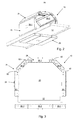
- FIGS. 2 and 3 views of the RFID tunnel of FIG. 1 without a support frame
- FIGS. 4 and 5 views of two standard modules
- FIG. 6 an exploded view for explaining the connection of two standard modules
- FIG. 7 a view of a further embodiment.
- An RFID reading tunnel 10 in accordance with the invention is mounted at a conveyor belt 12 in the embodiment in accordance with FIG. 1 .
- the conveyor belt 12 conveys objects, not shown, which bear an RFID transponder (also called an RFID tag) in a direction 14 through the tunnel 10 .
- RFID antennas 16 are arranged in the tunnel and transmit and receive corresponding RFID signals to be able to read in and/or write the transponders in a reading zone 20 within the tunnel 10 .
- Antennas 16 are connected to an RFID reader 18 for this purpose.
- the tunnel 10 and the conveyor belt 12 are mounted on a rack 22 .
- the reading zone 20 is bounded by the screen 24 forming the tunnel so that constant electromagnetic conditions are present in the reading zone 20 .
- the screen 24 comprises side walls 26 and cover parts 28 and, in the embodiments in accordance with FIGS. 1 to 3 , also lower parts 29 .
- the side walls 26 , cover parts 28 and lower parts 29 are formed in accordance with the invention by modules which, in the embodiment in accordance with FIGS. 1 to 3 , are made up only of two different standard modules 30 - 1 and 30 - 2 .
- the standard module 30 - 1 is shown in a perspective view in FIG. 5 and has a rectangular, tub-like base body 34 - 1 with a tub base 36 - 1 and longitudinal tub side walls 38 - 1 and 40 - 1 having a length L- 1 as well as end face tub walls 42 - 1 and 44 - 1 having a length B- 1 .
- One of the RFID antennas 16 is fastened in the interior of the tub-like base body 34 - 1 .
- the standard module 30 - 2 which is shown in a perspective view in FIG. 4 , has an analog design to the module 30 - 1 with a base body 34 - 2 , a tub base 36 - 2 , longitudinal tub side walls 38 - 2 and 40 - 2 as well as end face tub walls 42 - 2 and 44 - 2 .
- the width B- 2 of the module 30 - 2 is smaller.
- An absorber absorbing electromagnetic radiation is provided in the interior of the tubs 34 - 1 and 34 - 2 .
- a kit of predefined modules can be configured as standard modules, wherein the standard modules can comprise, in the described manner, simply the tub-like base body and can thus form a simple screen module or can contain an additional absorber or can contain an antenna or can contain both an antenna and an absorber.
- the standard modules can comprise, in the described manner, simply the tub-like base body and can thus form a simple screen module or can contain an additional absorber or can contain an antenna or can contain both an antenna and an absorber.
- Such a kit would then have four standard modules differing in design which can optionally each have two different widths.
- connection elements 50 are all configured as similar and are fixed at the end faces 42 - x and 44 - x for connecting the modules along their longitudinal sides 36 - x and 38 - x (“x” is a placeholder for “1” or “2”).
- the connection elements 30 comprise a metal plate 52 and connect two modules 30 - 1 and 30 - 2 by means of fastening means such as screws via correspondingly positioned holes 54 .
- the modules likewise have for the purpose correspondingly positioned holes 56 - 1 and 56 - 2 for the fastening means in their end faces.
- the holes 54 of the connection element 50 are positioned such that the connected modules 30 - 1 and 30 - 2 form an angle of 135°.
- connection element 50 - a is dimensioned and the holes 54 - a are positioned such that the connected modules include an angle of 120°.
- the reading tunnel comprises four standard modules 30 - 1 .
- Each standard module serves at least as a screen and at least one standard module has to include an RFID antenna so that an RFID reading is possible at all. It can be sensible to carry out an RFID reading from below in specific applications.
- a standard module having an antenna is arranged beneath the placing down device or conveying device; it screens the reading module in the tunnel from below and can read an RFID tag by means of the antenna.
- additional modules can be provided.
- Such an additional module generally has the same design as a standard module, that is it has the tub-like base body with the same dimensions as a standard module.
- an additional device is provided in the additional module such as a barcode reader for reading a barcode and/or a camera for detecting object features and/or a sensor, e.g. a laser scanner, for the volume determination and a sensor for the weight determination. Since the additional module is designed like a standard module, it can replace a standard module in the tunnel so that a reading tunnel equipped in this manner can satisfy further functions such as a barcode reading in addition to an RFID reading.
Landscapes
- Engineering & Computer Science (AREA)
- Physics & Mathematics (AREA)
- Health & Medical Sciences (AREA)
- Toxicology (AREA)
- General Physics & Mathematics (AREA)
- Artificial Intelligence (AREA)
- Computer Vision & Pattern Recognition (AREA)
- Theoretical Computer Science (AREA)
- Electromagnetism (AREA)
- General Health & Medical Sciences (AREA)
- Computer Networks & Wireless Communication (AREA)
- Discharge Of Articles From Conveyors (AREA)
- Shielding Devices Or Components To Electric Or Magnetic Fields (AREA)
- Support Of Aerials (AREA)
Abstract
Description
Claims (10)
Applications Claiming Priority (3)
| Application Number | Priority Date | Filing Date | Title |
|---|---|---|---|
| DE102012111986.4A DE102012111986A1 (en) | 2012-12-07 | 2012-12-07 | RFID reading tunnel for the identification of objects by means of RFID |
| DE102012111986 | 2012-12-07 | ||
| DE102012111986.4 | 2012-12-07 |
Publications (2)
| Publication Number | Publication Date |
|---|---|
| US20140158766A1 US20140158766A1 (en) | 2014-06-12 |
| US8893972B2 true US8893972B2 (en) | 2014-11-25 |
Family
ID=49578212
Family Applications (1)
| Application Number | Title | Priority Date | Filing Date |
|---|---|---|---|
| US14/093,085 Active US8893972B2 (en) | 2012-12-07 | 2013-11-29 | RFID reading tunnel for identifying objects by means of RFID |
Country Status (5)
| Country | Link |
|---|---|
| US (1) | US8893972B2 (en) |
| EP (1) | EP2741230B1 (en) |
| JP (1) | JP2014115994A (en) |
| CN (1) | CN103870857A (en) |
| DE (1) | DE102012111986A1 (en) |
Families Citing this family (16)
| Publication number | Priority date | Publication date | Assignee | Title |
|---|---|---|---|---|
| DE202013004511U1 (en) * | 2013-05-15 | 2014-08-18 | Checkpoint Systems, Inc. | System for writing RFID transponders |
| US9830486B2 (en) * | 2014-06-05 | 2017-11-28 | Avery Dennison Retail Information Services, Llc | RFID variable aperture read chamber crossfire |
| JP6146479B2 (en) | 2014-08-21 | 2017-06-14 | 株式会社村田製作所 | Method for reading article with RFID tag and RFID system |
| US11714975B2 (en) | 2014-10-28 | 2023-08-01 | Avery Dennison Retail Information Services Llc | High density read chambers for scanning and encoding RFID tagged items |
| US20160117530A1 (en) * | 2014-10-28 | 2016-04-28 | Avery Dennison Retail Branding and Information Solutions | Methods for scanning and encoding a plurality of rfid tagged items |
| CN104616103A (en) * | 2015-01-28 | 2015-05-13 | 佛山市威格特电气设备有限公司 | Tool intelligent self-service management method and self-service management terminal |
| US9922218B2 (en) | 2015-06-10 | 2018-03-20 | Avery Dennison Retail Information Services, Llc | RFID isolation tunnel with dynamic power indexing |
| CN105574982B (en) * | 2016-01-12 | 2018-09-25 | 深圳粤宝电子科技有限公司 | A kind of reading chinaware of wound core full bridge structure |
| CN106159463B (en) * | 2016-08-19 | 2023-03-24 | 杭州潮盛科技有限公司 | Antenna and reader |
| JP2018055634A (en) * | 2016-09-30 | 2018-04-05 | マスプロ電工株式会社 | RFID gate system |
| CN106403842B (en) * | 2016-10-31 | 2019-12-31 | 紫光智云(江苏)物联网科技有限公司 | System and method for electronic tracking of target items |
| FR3059448B1 (en) | 2016-11-29 | 2019-05-17 | Wid | ASSOCIATED MANAGEMENT SYSTEM, INSTALLATION AND MOUNTING METHOD |
| CN107092845A (en) * | 2017-03-28 | 2017-08-25 | 杭州利邮通信器材有限公司 | A kind of express box batch scanning system |
| CN109127444A (en) * | 2018-10-18 | 2019-01-04 | 昆明昆船逻根机场物流系统有限公司 | The movable label identification device and control method of a kind of Luggage from flights in loading place |
| JP7278182B2 (en) * | 2019-09-13 | 2023-05-19 | 東芝テック株式会社 | RFID tag reader |
| CN119631078A (en) * | 2022-08-05 | 2025-03-14 | 佐藤控股株式会社 | RFID Tunnel Reader |
Citations (4)
| Publication number | Priority date | Publication date | Assignee | Title |
|---|---|---|---|---|
| DE10040550A1 (en) | 2000-08-15 | 2002-03-07 | Kahl Elektrotechnik Gmbh | Device for the automatic detection of luggage provided with electronic tags |
| EP1064568B1 (en) | 1998-03-23 | 2005-11-23 | Magellan Technology Pty. Limited | An interrogator for interrogating an rfid |
| WO2009002156A1 (en) | 2007-06-28 | 2008-12-31 | Vanderlande Industries Nederland B.V. | Device for identifying pieces of luggage provided with an rfid tag |
| US20090134221A1 (en) | 2000-11-24 | 2009-05-28 | Xiaoxun Zhu | Tunnel-type digital imaging-based system for use in automated self-checkout and cashier-assisted checkout operations in retail store environments |
Family Cites Families (4)
| Publication number | Priority date | Publication date | Assignee | Title |
|---|---|---|---|---|
| JPS561910U (en) * | 1979-06-20 | 1981-01-09 | ||
| US7218231B2 (en) * | 2004-07-29 | 2007-05-15 | Omnicell, Inc. | Method and apparatus for preparing an item with an RFID tag |
| JP4384083B2 (en) * | 2005-06-03 | 2009-12-16 | 三菱電線工業株式会社 | Conveyance management device |
| JP4238922B2 (en) * | 2007-07-09 | 2009-03-18 | 三菱電機株式会社 | Patch antenna |
-
2012
- 2012-12-07 DE DE102012111986.4A patent/DE102012111986A1/en not_active Withdrawn
-
2013
- 2013-11-15 EP EP13193007.5A patent/EP2741230B1/en active Active
- 2013-11-25 JP JP2013242830A patent/JP2014115994A/en active Pending
- 2013-11-29 US US14/093,085 patent/US8893972B2/en active Active
- 2013-12-09 CN CN201310659447.5A patent/CN103870857A/en active Pending
Patent Citations (4)
| Publication number | Priority date | Publication date | Assignee | Title |
|---|---|---|---|---|
| EP1064568B1 (en) | 1998-03-23 | 2005-11-23 | Magellan Technology Pty. Limited | An interrogator for interrogating an rfid |
| DE10040550A1 (en) | 2000-08-15 | 2002-03-07 | Kahl Elektrotechnik Gmbh | Device for the automatic detection of luggage provided with electronic tags |
| US20090134221A1 (en) | 2000-11-24 | 2009-05-28 | Xiaoxun Zhu | Tunnel-type digital imaging-based system for use in automated self-checkout and cashier-assisted checkout operations in retail store environments |
| WO2009002156A1 (en) | 2007-06-28 | 2008-12-31 | Vanderlande Industries Nederland B.V. | Device for identifying pieces of luggage provided with an rfid tag |
Non-Patent Citations (2)
| Title |
|---|
| Corresponding to EPO Office Action dated Mar. 19, 2014 for 13193007.5-1811. |
| Examination Report issued in German Application No. 10 2012 222 986.4 dated Aug. 14, 2013, 6 pages. |
Also Published As
| Publication number | Publication date |
|---|---|
| US20140158766A1 (en) | 2014-06-12 |
| EP2741230B1 (en) | 2016-03-02 |
| CN103870857A (en) | 2014-06-18 |
| DE102012111986A1 (en) | 2014-06-12 |
| JP2014115994A (en) | 2014-06-26 |
| EP2741230A1 (en) | 2014-06-11 |
Similar Documents
| Publication | Publication Date | Title |
|---|---|---|
| US8893972B2 (en) | RFID reading tunnel for identifying objects by means of RFID | |
| EP3542302B1 (en) | Interference-reducing rfid reader | |
| US20120019364A1 (en) | Rfid reading apparatus | |
| US9446880B2 (en) | Floor element for a cargo container and/or a cargo pallet, and method for production of a corresponding floor element | |
| AU2011284797C1 (en) | Luggage processing station | |
| US6967579B1 (en) | Radio frequency identification for advanced security screening and sortation of baggage | |
| US9830486B2 (en) | RFID variable aperture read chamber crossfire | |
| RU2014144405A (en) | METHOD AND SYSTEM FOR RECEIVING AND REGISTRATION OF BAGGAGE ON FLIGHTS OF AIRLINES | |
| RU2013139711A (en) | DEVICE AND METHOD FOR ACCOUNTING COMMODITY OF A SHOPPING POINT AND / OR WAREHOUSE, AS WELL AS MANAGED BY THIS EQUIPMENT | |
| GB2555554A (en) | Method and apparatus pertaining to an RFID tag reader antenna array | |
| CA2939977A1 (en) | Luggage processing station and system thereof | |
| KR101274585B1 (en) | Position information decision apparatus of rfid tag and the method thereof | |
| CN105151616B (en) | Express delivery end warehouse machine and automation services method | |
| US10139265B2 (en) | System and method for determining weight of freight units and baggage | |
| MX2014015129A (en) | Rfid smart garment. | |
| CN103381964A (en) | Metal detector belt with integrated weighing cell | |
| CN104573582A (en) | Detection device for multi-angle detection of cargo RFID tags and belt conveyor | |
| US20070075866A1 (en) | Apparatus for encapsulating radio frequency identification (RFID) antennae | |
| KR101330363B1 (en) | Directional rfid label tag for measuring postal matter delivery service | |
| CN204926103U (en) | RFID electronic tags discerns passageway suitable for on luggage delivery chute | |
| US20160159498A1 (en) | Luggage handling control installation | |
| DE202012104776U1 (en) | RFID reading tunnel for the identification of objects by means of RFID | |
| AU2016201979B2 (en) | Luggage Processing Station | |
| CN223078691U (en) | Airport Baggage Identification System | |
| DE102015214621B4 (en) | Tail lift for a truck, method of loading goods |
Legal Events
| Date | Code | Title | Description |
|---|---|---|---|
| AS | Assignment |
Owner name: SICK AG, GERMANY Free format text: ASSIGNMENT OF ASSIGNORS INTEREST;ASSIGNORS:WEHRLE, KLEMENS;PASKE, RALF;REEL/FRAME:031692/0123 Effective date: 20131121 |
|
| STCF | Information on status: patent grant |
Free format text: PATENTED CASE |
|
| MAFP | Maintenance fee payment |
Free format text: PAYMENT OF MAINTENANCE FEE, 4TH YEAR, LARGE ENTITY (ORIGINAL EVENT CODE: M1551) Year of fee payment: 4 |
|
| MAFP | Maintenance fee payment |
Free format text: PAYMENT OF MAINTENANCE FEE, 8TH YEAR, LARGE ENTITY (ORIGINAL EVENT CODE: M1552); ENTITY STATUS OF PATENT OWNER: LARGE ENTITY Year of fee payment: 8 |