US8882418B2 - Locking device for an equipment item on a locking track - Google Patents
Locking device for an equipment item on a locking track Download PDFInfo
- Publication number
- US8882418B2 US8882418B2 US13/945,345 US201313945345A US8882418B2 US 8882418 B2 US8882418 B2 US 8882418B2 US 201313945345 A US201313945345 A US 201313945345A US 8882418 B2 US8882418 B2 US 8882418B2
- Authority
- US
- United States
- Prior art keywords
- support component
- locking
- contour
- guide
- section
- Prior art date
- Legal status (The legal status is an assumption and is not a legal conclusion. Google has not performed a legal analysis and makes no representation as to the accuracy of the status listed.)
- Active
Links
Images


Classifications
-
- B—PERFORMING OPERATIONS; TRANSPORTING
- B64—AIRCRAFT; AVIATION; COSMONAUTICS
- B64D—EQUIPMENT FOR FITTING IN OR TO AIRCRAFT; FLIGHT SUITS; PARACHUTES; ARRANGEMENTS OR MOUNTING OF POWER PLANTS OR PROPULSION TRANSMISSIONS IN AIRCRAFT
- B64D11/00—Passenger or crew accommodation; Flight-deck installations not otherwise provided for
- B64D11/06—Arrangements of seats, or adaptations or details specially adapted for aircraft seats
- B64D11/0696—Means for fastening seats to floors, e.g. to floor rails
Definitions
- the present application relates to a device for locking an equipment item onto a locking track attached to the floor of a cabin, including two parallel retaining edges divided by a longitudinal slot and a number of spatially separated openings, wherein the device has on its upper side means for locking the equipment item and on its lower side includes at least two locking projections the size and the arrangement of which are adapted to at least two adjacent openings, and wherein by shifting the locking projections in the longitudinal direction of the locking track until the locking projections are located between two adjacent openings, a positive connection between the device and the locking track can be produced.
- Such a device is known from U.S. Pat. No. 5,871,318, for example, and is used in particular for the longitudinal shifting of aircraft seats along locking tracks that are attached onto the cabin floor of an aircraft.
- the device In order to fasten the aircraft seats onto the locking tracks, the device is initially aligned such that a support component with molded projections is aligned with the circular openings, so that this can be moved through the longitudinal slot in the locking track.
- the support component is then moved by half the distance between adjacent openings in the longitudinal direction of the track, wherein the T-shaped cross-sectional projections engage behind the retaining edges on both sides of the locking track and prevent the support component from coming out of the locking track.
- locking parts having a corresponding contour are then moved down by the support component, so that these are retained in the openings which are now located below.
- the locking parts are pushed against the retaining edges, which results in locking the support component and thus the seat attached to it in the track.
- the support components after having been inserted into the locking track, must be moved as accurately as possible by half the distance of the opening, so that the locking parts engage into the openings and thus making secure locking possible. Since several seats are normally combined in one row and are arranged on one seat support, it is necessary that this entire row of seats must be moved. This process requires some time for assembly, particularly if the distance by which the row of seats is shifted deviates too greatly from the setpoint, and locking is not possible initially until some fine alignment has been done. This shifting process can also result in some tilting and can thus produce jamming.
- the object of the present application is to prevent the above disadvantages and to facilitate a structurally simple device for locking an equipment item onto a locking track attached to the floor of a cabin, permitting quicker and uncomplicated assembly.
- the device according to the present application includes a support component, the underside of which includes an insertion section that is adapted to the longitudinal slot contour which can be inserted into the locking track, and that an insertable sliding part is guided in the locking track so that it can be shifted longitudinally, the outside contour of which corresponds to the insertion section, wherein the sliding part can be shifted in the locking track relative to the support component to lock the support component.
- This design has the advantage that the support component has to be inserted only into the locking track, and therefore does not need to be shifted in the longitudinal direction of the track after the equipment item (e.g. the row of seats) has been inserted, but instead remains in this position. Rather, the sliding part that in the unlocked position is arranged below the support component is shifted by half the distance between adjacent openings. The support component is positively held in the locking track in this position. For this purpose, the outside contour of the sliding part does not have to completely match that of the insertion section, but it is rather important that the device can be inserted into the locking track without the possibility of entanglement during insertion or retraction.
- the insertion section has the contour of two or three adjacent openings. In this manner it is accomplished that a solid contact of the support component on the locking track is ensured.
- the contour of the sliding part corresponds to the contour of two or three adjacent openings. This prevents the sliding part from tilting during its movement.
- the bottom of the support component comprises a T-shaped groove in the longitudinal direction, and the sliding part has a corresponding guide section with a T-shaped cross-section. This facilitates good and secure guidance of the sliding part in the support component.
- T-shaped is to be understood in that the groove and/or guide have the shape of a swallowtail, or similar.
- the sliding part is essentially L-shaped with an actuating projection extending vertically.
- This actuating projection which is arranged ahead of the front face of the support component projects from the longitudinal slot and makes it possible to shift the sliding part within the locking track below the support component from outside of the longitudinal slot in the longitudinal direction of the track.
- the actuating projection is preferably positioned in the locked condition on the support component or on a limit stop molded on the support component. In the unlocked position, the actuating projection will preferably be spaced apart from the support component, the distance of which corresponds to half of the distance between adjacent openings.
- the sliding part can be moved relative to the support component by a distance which corresponds to half of the distance between adjacent openings in the locking track.
- corresponding limits are provided either in the guide of the sliding part in the support component, or in another position.
- An easy design consist in that the actuating projection in the locked position bears against the support component or against another limit stop provided on it, and that a projection is formed on the end of the T-shaped guide of the sliding part, which then strikes against the support component.
- a guide projection is molded onto the actuating projection and a correspondingly shaped guide recess is assigned to it in the support component, wherein the guide projection during the shift of the sliding part in the locked condition slides into the guide recess.
- the support component has a locking guide on one front face, in which the locking element is held movable, and that a counterpart is formed in the sliding part which accommodates the locking element, so that the sliding part is locked with respect to the support component when the locking element is in the locked position.
- the locking element will preferably be a vertically movable pin and the counterpart a recess. This is a very straightforward design, structurally.
- the locking element is preferably placed elastically into the closed position so that it will automatically engage when the locked position is reached. This design makes the assembly particularly easy and fast, because it requires no separate locking. A further advantage is if the locking element engages audibly or is perceivable haptically.
- the locking element will preferably have unlocking means that can be manually actuated, such as a handle or an annular section through which a finger can be inserted, in order to move the locking element into the unlocked position manually.
- unlocking means can be manually actuated, such as a handle or an annular section through which a finger can be inserted, in order to move the locking element into the unlocked position manually.
- the locking element can have a small projection in the guided center section, and a corresponding guide for the projection is provided in the locking guide, so that in both and positions, the pin can be put into a locked position by a 90° rotation in each case.
- the locking element preferably comprises an indicator to indicate the locked condition, such as a red section of the pin that protrudes in the unlocked condition to indicate that locking has not occurred.
- a preferred use of the device according to the present application is in an aircraft, in particular in a passenger aircraft, and the equipment item preferably is an aircraft seat or a row of aircraft seats.
- FIG. 1 is a perspective cutaway view of a locking track
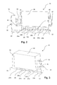
- FIG. 2 is a perspective illustration of the device according to the present application in the unlocked condition
- FIG. 3 is a perspective illustration of the device according to the present application in the locked condition
- FIG. 4 is a longitudinal section through the device according to the present application.
- FIG. 5 is a front elevation of the device according to the present application.
- FIG. 1 illustrates a locking track 10 , as typically arranged in aircraft, particularly in passenger aircraft, for attaching equipment items such as seats, seat rows, partitions, galleys, or luggage racks.
- the locking track 10 includes two parallel retaining edges 12 a , 12 b , between which a longitudinal slot 14 is defined, including circular openings 16 spaced apart evenly, such as at one inch.
- FIG. 2 is a device 18 according to the present application as a perspective illustration looking at the side from below, in the unlocked condition.
- the identical device 18 is shown in FIG. 3 as a perspective illustration looking at the side from above, in the locked condition.
- FIG. 4 is the identical device 18 also in the locked condition, illustrated as a vertical longitudinal section.
- the device 18 shown in FIGS. 1 to 4 includes a support component 20 , on the upper side of which devices are attached (not shown) for attaching equipment items.
- an insertion section 22 is molded, which has a cross-sectional contour which matches the contour of the longitudinal slot 14 in the locking track 10 with the openings 16 .
- the insertion section 22 in particular includes three cylindrical sections 24 a , the outside diameter of which is slightly smaller than the diameter of the openings 16 and which are arranged equally spaced apart as the openings 16 . These three cylindrical sections 24 a are connected to each other by means of straight-line sections 26 , the width of which corresponds to the width of the longitudinal slot 14 in the locking track 10 .
- the device 18 furthermore includes a sliding part 30 that is essentially L-shaped and which includes a horizontal section 32 and an actuating projection 34 .
- the horizontal section 32 has the same outside contour as the insertion section 22 of the support component 20 , and therefore also includes three cylindrical sections 24 b , which in the unlocked embodiment shown in FIG. 2 are aligned with the cylindrical sections 24 a of the insertion section 22 .
- the sliding part 30 has a T-shaped or swallowtail-shaped guide 36 , which guides the sliding part 30 in the support component 20 .
- a guide projection 38 is molded onto the actuating projection 34 , which can engage in a matched guide recess 40 .
- the guide projection 38 In the unlocked position represented in FIG. 2 , the guide projection 38 is located so that it is disengaged from the guide recess 40 , while in the locked position shown in FIG. 3 , the guide projection 38 and the guide recess 40 are engaged, as a result of which the rigidity of the connection between support component 20 and sliding part 30 is increased in the locked condition.
- a locking guide 42 for accommodating a locking element 44 is furthermore provided on the support component 20 , which can slide into a recess 46 formed in the sliding part 30 .
- the locking element 44 is pushed down by spring devices (not shown) and then automatically latches into the recess 46 as soon as the locking element 44 and the recess 46 are aligned with each other.
- it has means (not shown), for example an annular section molded onto the upper end through which a finger can be inserted to then pull it.
- the locking element 44 will preferably have a bright color or a fluorescent coating so that it can be seen from outside whether it is in a latched position or not.
- the device 18 Prior to the assembly on the locking track 10 , the device 18 according to the present application will be in the position shown in FIG. 2 , in which the cylindrical sections 24 a and 24 b are aligned, and can therefore be inserted into the openings 16 of the locking track 10 . As mentioned previously, in this position the guide projection 38 is disengaged from the guide recess 40 and the locking element 44 is disengaged from the recess 46 . In this position, the device 18 will therefore be guided in the longitudinal slot 14 of the locking track 10 .
- the sliding part 30 is moved into the locked position shown in FIGS. 3 and 4 .
- the cylindrical sections 24 b of the horizontal section 32 are located offset by half the distance between adjacent cylindrical sections 24 b , which distance is identical to the distance between adjacent cylindrical sections 24 a and also identical to the distance between adjacent openings 16 .
- the cylindrical sections 24 b are positioned below the retaining edges 12 a , 12 b , of the locking track 10 , so that the support component 20 is thus retained in the locking track 10 .
- the guide projection 38 is engaged in the guide recess 40 and thus increases the rigidity of the connection.
- the locking element 44 is engaged in the recess 46 and thus prevents a reverse movement of the sliding part 30 relative to the support component 20 .
- the sections 24 b of the sliding part 30 can have a slight bevel in the longitudinal direction and/or in the direction of movement. In this way, the slack during the shifting of the sliding part 30 would increasingly become smaller automatically, which would ultimately result in clamping.
Abstract
Description
- 10 Locking track;
- 12 a, b Retaining edges;
- 14 Longitudinal slot;
- 16 Openings;
- 18 Device;
- 20 Support component;
- 22 Insertion section;
- 24 a, b Sections;
- 26 Sections;
- 28 Bottom surface;
- 30 Sliding part;
- 32 Horizontal section;
- 34 Actuating projection;
- 36 Guide;
- 38 Guide projection;
- 40 Guide recess;
- 42 Locking guide;
- 44 Locking element; and
- 46 Recess.
Claims (15)
Applications Claiming Priority (3)
| Application Number | Priority Date | Filing Date | Title |
|---|---|---|---|
| DE102012106865.8 | 2012-07-27 | ||
| DE102012106865.8A DE102012106865B4 (en) | 2012-07-27 | 2012-07-27 | Fixing device for a piece of equipment on a Fixierschiene |
| DE102012106865 | 2012-07-27 |
Publications (2)
| Publication Number | Publication Date |
|---|---|
| US20140030039A1 US20140030039A1 (en) | 2014-01-30 |
| US8882418B2 true US8882418B2 (en) | 2014-11-11 |
Family
ID=48877063
Family Applications (1)
| Application Number | Title | Priority Date | Filing Date |
|---|---|---|---|
| US13/945,345 Active US8882418B2 (en) | 2012-07-27 | 2013-07-18 | Locking device for an equipment item on a locking track |
Country Status (3)
| Country | Link |
|---|---|
| US (1) | US8882418B2 (en) |
| EP (1) | EP2690017B8 (en) |
| DE (1) | DE102012106865B4 (en) |
Families Citing this family (2)
| Publication number | Priority date | Publication date | Assignee | Title |
|---|---|---|---|---|
| DE102010053892B4 (en) * | 2010-12-09 | 2015-01-29 | Airbus Operations Gmbh | Seat adjustment device as well as aircraft or spacecraft |
| EP3009350A1 (en) * | 2014-10-17 | 2016-04-20 | Airbus Defence and Space GmbH | Seat-mounting systems, seat or group of seats, aircraft cabin and method for attaching a seat or a group of seats |
Citations (3)
| Publication number | Priority date | Publication date | Assignee | Title |
|---|---|---|---|---|
| US4496271A (en) * | 1982-09-30 | 1985-01-29 | East/West Industries, Inc. | Restraining fittings |
| EP0583295B1 (en) | 1991-04-27 | 1994-11-23 | MICHLER, Walter | Quick-release fastening device |
| EP1342662A1 (en) | 2002-03-08 | 2003-09-10 | Antar Daouk | Fixation device of an equipment in rails of aeronautic type |
Family Cites Families (4)
| Publication number | Priority date | Publication date | Assignee | Title |
|---|---|---|---|---|
| US5871318A (en) | 1997-11-12 | 1999-02-16 | Be Aerospace, Inc. | Quick-release track fastener |
| FR2953489B1 (en) * | 2009-12-09 | 2012-01-13 | Attax | SYSTEM FOR FASTENING A SEAT, IN PARTICULAR AN AIRCRAFT AND SEAT COMPRISING AT LEAST ONE SUCH SYSTEM. |
| FR2957331B1 (en) * | 2010-03-12 | 2012-07-13 | Attax | SYSTEM FOR FASTENING A SEAT IN AN AIRCRAFT RAIL |
| FR2957330B1 (en) * | 2010-03-12 | 2012-04-20 | Attax | AIRCRAFT SEAT ATTACHING SYSTEM |
-
2012
- 2012-07-27 DE DE102012106865.8A patent/DE102012106865B4/en active Active
-
2013
- 2013-07-18 US US13/945,345 patent/US8882418B2/en active Active
- 2013-07-24 EP EP13177777.3A patent/EP2690017B8/en active Active
Patent Citations (4)
| Publication number | Priority date | Publication date | Assignee | Title |
|---|---|---|---|---|
| US4496271A (en) * | 1982-09-30 | 1985-01-29 | East/West Industries, Inc. | Restraining fittings |
| EP0583295B1 (en) | 1991-04-27 | 1994-11-23 | MICHLER, Walter | Quick-release fastening device |
| US5489172A (en) | 1991-04-27 | 1996-02-06 | Michler; Walter | Quick-release fastening device |
| EP1342662A1 (en) | 2002-03-08 | 2003-09-10 | Antar Daouk | Fixation device of an equipment in rails of aeronautic type |
Also Published As
| Publication number | Publication date |
|---|---|
| US20140030039A1 (en) | 2014-01-30 |
| EP2690017A2 (en) | 2014-01-29 |
| EP2690017B1 (en) | 2017-02-15 |
| DE102012106865A1 (en) | 2014-01-30 |
| EP2690017A3 (en) | 2015-03-25 |
| EP2690017B8 (en) | 2017-04-26 |
| DE102012106865B4 (en) | 2016-11-03 |
Similar Documents
| Publication | Publication Date | Title |
|---|---|---|
| JP6591646B2 (en) | ISOFIX connector and child seat | |
| US10124706B2 (en) | Guide device | |
| US9718410B2 (en) | Assembly for connecting a roof rack to a vehicle | |
| US8882418B2 (en) | Locking device for an equipment item on a locking track | |
| US7824207B2 (en) | Plug-in connector with a sleeve with an unlocking member | |
| US8939424B2 (en) | Seat slide device | |
| US10640027B2 (en) | Table unit | |
| US10462922B2 (en) | Locking device for rackable electronic equipment | |
| US9726275B2 (en) | Shift lever of automotive transmission | |
| US7455543B2 (en) | Electric plug connector with bayonet ring and secondary lock | |
| US9730495B2 (en) | Side-release buckle | |
| US9515411B2 (en) | Connector with lever | |
| US9738387B2 (en) | Galley segment for a cabin of a vehicle, cabin of a vehicle and aircraft having a cabin with such a galley segment | |
| CN210454662U (en) | Roof rack system and cross member apparatus | |
| US20150031230A1 (en) | Connector | |
| US9461420B2 (en) | Connector holder | |
| US9831604B2 (en) | Plug connector system | |
| US10214121B2 (en) | Method of assembling a child restraint having a tiltable juvenile vehicle seat | |
| US20110107560A1 (en) | Buckle assemblies for personal restraint systems and associated methods of use and manufacture | |
| US20170211607A1 (en) | Ball Lock Pin | |
| CN112236642B (en) | Rapid release system for body armor | |
| CN103493163A (en) | Lockout device | |
| ES2932650T3 (en) | Seat accessories for attaching seats to seat guides in a vehicle and related systems and methods | |
| DE102015110892A1 (en) | Covering device for covering a loading space of a motor vehicle | |
| DE102011076009A1 (en) | Plug holder for attaching equipment element to rear construction structure, has locking device that is provided with sliding segment which is provided with arc-shaped locking surface, and plug that is provided with retaining bolt |
Legal Events
| Date | Code | Title | Description |
|---|---|---|---|
| AS | Assignment |
Owner name: EADS DEUTSCHLAND GMBH, GERMANY Free format text: ASSIGNMENT OF ASSIGNORS INTEREST;ASSIGNORS:ROLLFINK, PATRICK;POMMERS, MARTINS;SIGNING DATES FROM 20130909 TO 20130910;REEL/FRAME:031529/0567 |
|
| STCF | Information on status: patent grant |
Free format text: PATENTED CASE |
|
| FEPP | Fee payment procedure |
Free format text: PAYOR NUMBER ASSIGNED (ORIGINAL EVENT CODE: ASPN); ENTITY STATUS OF PATENT OWNER: LARGE ENTITY |
|
| AS | Assignment |
Owner name: AIRBUS DEFENCE AND SPACE GMBH, GERMANY Free format text: CHANGE OF NAME;ASSIGNOR:EADS DEUTSCHLAND GMBH;REEL/FRAME:036100/0801 Effective date: 20150701 |
|
| AS | Assignment |
Owner name: AIRBUS DEFENCE AND SPACE GMBH, GERMANY Free format text: CORRECTIVE ASSIGNMENT TO DELETE APPLICATION NUMBER 14/443003 PREVIOUSLY RECORDED AT REEL: 036100 FRAME: 0801. ASSIGNOR(S) HEREBY CONFIRMS THE CHANGE OF NAME;ASSIGNOR:EADS DEUTSCHLAND GMBH;REEL/FRAME:036144/0462 Effective date: 20150701 |
|
| MAFP | Maintenance fee payment |
Free format text: PAYMENT OF MAINTENANCE FEE, 4TH YEAR, LARGE ENTITY (ORIGINAL EVENT CODE: M1551) Year of fee payment: 4 |
|
| MAFP | Maintenance fee payment |
Free format text: PAYMENT OF MAINTENANCE FEE, 8TH YEAR, LARGE ENTITY (ORIGINAL EVENT CODE: M1552); ENTITY STATUS OF PATENT OWNER: LARGE ENTITY Year of fee payment: 8 |