US8880357B2 - Apparatus for estimating a resonant frequency of a wind turbine tower - Google Patents
Apparatus for estimating a resonant frequency of a wind turbine tower Download PDFInfo
- Publication number
- US8880357B2 US8880357B2 US13/993,228 US201013993228A US8880357B2 US 8880357 B2 US8880357 B2 US 8880357B2 US 201013993228 A US201013993228 A US 201013993228A US 8880357 B2 US8880357 B2 US 8880357B2
- Authority
- US
- United States
- Prior art keywords
- filter
- module
- frequency
- wind turbine
- band
- Prior art date
- Legal status (The legal status is an assumption and is not a legal conclusion. Google has not performed a legal analysis and makes no representation as to the accuracy of the status listed.)
- Expired - Fee Related
Links
- 238000004422 calculation algorithm Methods 0.000 claims abstract description 62
- 230000003044 adaptive effect Effects 0.000 claims abstract description 55
- 230000001133 acceleration Effects 0.000 claims abstract description 43
- 230000002238 attenuated effect Effects 0.000 claims abstract description 21
- 238000005259 measurement Methods 0.000 claims description 15
- 230000004044 response Effects 0.000 claims description 12
- 238000000034 method Methods 0.000 claims description 9
- 230000010355 oscillation Effects 0.000 description 15
- 230000006870 function Effects 0.000 description 7
- 238000004364 calculation method Methods 0.000 description 3
- 230000008859 change Effects 0.000 description 3
- 230000000694 effects Effects 0.000 description 3
- 230000001419 dependent effect Effects 0.000 description 2
- 238000009795 derivation Methods 0.000 description 2
- 230000004069 differentiation Effects 0.000 description 2
- 239000000463 material Substances 0.000 description 2
- 230000003595 spectral effect Effects 0.000 description 2
- 238000007792 addition Methods 0.000 description 1
- 230000005540 biological transmission Effects 0.000 description 1
- 238000013016 damping Methods 0.000 description 1
- 238000010586 diagram Methods 0.000 description 1
- 230000005611 electricity Effects 0.000 description 1
- 238000003379 elimination reaction Methods 0.000 description 1
- 230000005284 excitation Effects 0.000 description 1
- 230000008569 process Effects 0.000 description 1
- 230000003068 static effect Effects 0.000 description 1
- 238000007619 statistical method Methods 0.000 description 1
Images


Classifications
-
- G—PHYSICS
- G01—MEASURING; TESTING
- G01N—INVESTIGATING OR ANALYSING MATERIALS BY DETERMINING THEIR CHEMICAL OR PHYSICAL PROPERTIES
- G01N29/00—Investigating or analysing materials by the use of ultrasonic, sonic or infrasonic waves; Visualisation of the interior of objects by transmitting ultrasonic or sonic waves through the object
- G01N29/04—Analysing solids
- G01N29/12—Analysing solids by measuring frequency or resonance of acoustic waves
-
- F03D11/04—
-
- F—MECHANICAL ENGINEERING; LIGHTING; HEATING; WEAPONS; BLASTING
- F03—MACHINES OR ENGINES FOR LIQUIDS; WIND, SPRING, OR WEIGHT MOTORS; PRODUCING MECHANICAL POWER OR A REACTIVE PROPULSIVE THRUST, NOT OTHERWISE PROVIDED FOR
- F03D—WIND MOTORS
- F03D13/00—Assembly, mounting or commissioning of wind motors; Arrangements specially adapted for transporting wind motor components
- F03D13/20—Arrangements for mounting or supporting wind motors; Masts or towers for wind motors
-
- F—MECHANICAL ENGINEERING; LIGHTING; HEATING; WEAPONS; BLASTING
- F03—MACHINES OR ENGINES FOR LIQUIDS; WIND, SPRING, OR WEIGHT MOTORS; PRODUCING MECHANICAL POWER OR A REACTIVE PROPULSIVE THRUST, NOT OTHERWISE PROVIDED FOR
- F03D—WIND MOTORS
- F03D17/00—Monitoring or testing of wind motors, e.g. diagnostics
-
- G—PHYSICS
- G01—MEASURING; TESTING
- G01H—MEASUREMENT OF MECHANICAL VIBRATIONS OR ULTRASONIC, SONIC OR INFRASONIC WAVES
- G01H13/00—Measuring resonant frequency
-
- F—MECHANICAL ENGINEERING; LIGHTING; HEATING; WEAPONS; BLASTING
- F03—MACHINES OR ENGINES FOR LIQUIDS; WIND, SPRING, OR WEIGHT MOTORS; PRODUCING MECHANICAL POWER OR A REACTIVE PROPULSIVE THRUST, NOT OTHERWISE PROVIDED FOR
- F03D—WIND MOTORS
- F03D9/00—Adaptations of wind motors for special use; Combinations of wind motors with apparatus driven thereby; Wind motors specially adapted for installation in particular locations
- F03D9/20—Wind motors characterised by the driven apparatus
- F03D9/25—Wind motors characterised by the driven apparatus the apparatus being an electrical generator
- F03D9/255—Wind motors characterised by the driven apparatus the apparatus being an electrical generator connected to electrical distribution networks; Arrangements therefor
-
- F—MECHANICAL ENGINEERING; LIGHTING; HEATING; WEAPONS; BLASTING
- F05—INDEXING SCHEMES RELATING TO ENGINES OR PUMPS IN VARIOUS SUBCLASSES OF CLASSES F01-F04
- F05B—INDEXING SCHEME RELATING TO WIND, SPRING, WEIGHT, INERTIA OR LIKE MOTORS, TO MACHINES OR ENGINES FOR LIQUIDS COVERED BY SUBCLASSES F03B, F03D AND F03G
- F05B2260/00—Function
- F05B2260/80—Diagnostics
-
- F—MECHANICAL ENGINEERING; LIGHTING; HEATING; WEAPONS; BLASTING
- F05—INDEXING SCHEMES RELATING TO ENGINES OR PUMPS IN VARIOUS SUBCLASSES OF CLASSES F01-F04
- F05B—INDEXING SCHEME RELATING TO WIND, SPRING, WEIGHT, INERTIA OR LIKE MOTORS, TO MACHINES OR ENGINES FOR LIQUIDS COVERED BY SUBCLASSES F03B, F03D AND F03G
- F05B2260/00—Function
- F05B2260/96—Preventing, counteracting or reducing vibration or noise
-
- F—MECHANICAL ENGINEERING; LIGHTING; HEATING; WEAPONS; BLASTING
- F05—INDEXING SCHEMES RELATING TO ENGINES OR PUMPS IN VARIOUS SUBCLASSES OF CLASSES F01-F04
- F05B—INDEXING SCHEME RELATING TO WIND, SPRING, WEIGHT, INERTIA OR LIKE MOTORS, TO MACHINES OR ENGINES FOR LIQUIDS COVERED BY SUBCLASSES F03B, F03D AND F03G
- F05B2270/00—Control
- F05B2270/40—Type of control system
- F05B2270/404—Type of control system active, predictive, or anticipative
-
- Y—GENERAL TAGGING OF NEW TECHNOLOGICAL DEVELOPMENTS; GENERAL TAGGING OF CROSS-SECTIONAL TECHNOLOGIES SPANNING OVER SEVERAL SECTIONS OF THE IPC; TECHNICAL SUBJECTS COVERED BY FORMER USPC CROSS-REFERENCE ART COLLECTIONS [XRACs] AND DIGESTS
- Y02—TECHNOLOGIES OR APPLICATIONS FOR MITIGATION OR ADAPTATION AGAINST CLIMATE CHANGE
- Y02E—REDUCTION OF GREENHOUSE GAS [GHG] EMISSIONS, RELATED TO ENERGY GENERATION, TRANSMISSION OR DISTRIBUTION
- Y02E10/00—Energy generation through renewable energy sources
- Y02E10/70—Wind energy
- Y02E10/72—Wind turbines with rotation axis in wind direction
-
- Y—GENERAL TAGGING OF NEW TECHNOLOGICAL DEVELOPMENTS; GENERAL TAGGING OF CROSS-SECTIONAL TECHNOLOGIES SPANNING OVER SEVERAL SECTIONS OF THE IPC; TECHNICAL SUBJECTS COVERED BY FORMER USPC CROSS-REFERENCE ART COLLECTIONS [XRACs] AND DIGESTS
- Y02—TECHNOLOGIES OR APPLICATIONS FOR MITIGATION OR ADAPTATION AGAINST CLIMATE CHANGE
- Y02E—REDUCTION OF GREENHOUSE GAS [GHG] EMISSIONS, RELATED TO ENERGY GENERATION, TRANSMISSION OR DISTRIBUTION
- Y02E10/00—Energy generation through renewable energy sources
- Y02E10/70—Wind energy
- Y02E10/728—Onshore wind turbines
Definitions
- the invention relates to an apparatus for estimating a resonant frequency of a wind turbine tower comprising a measuring module adapted for measuring acceleration values of the wind turbine tower wherein the acceleration values represent acceleration of the wind turbine tower, as well as a method of determining a resonant frequency of a wind turbine tower, comprising receiving acceleration measurement values of an acceleration of a wind turbine tower.
- a wind turbine generates electrical energy by converting the energy in the wind.
- the electrical energy can be supplied to the electric power transmission network.
- US patent application 2009/0230682 A1 discloses an apparatus for determining a resonant frequency of a wind turbine tower.
- the apparatus includes a processing unit configured to receive an acceleration measurement value, and a memory configured to store a series of acceleration measurement values.
- the processing unit includes a Fourier transform module configured to calculate a spectral vector based on calculating a convolution-based fast Fourier transform of the series of acceleration measurement values.
- a resonant frequency calculation module calculates the tower resonant frequency based on the calculated spectral vector.
- the object can be achieved by means of an apparatus for estimating a resonant frequency of a wind turbine tower, comprising a measuring module adapted for measuring acceleration values of the wind turbine tower wherein the acceleration values represent acceleration of the wind turbine tower, a filter module adapted for receiving the measured acceleration values, the filter module comprises a variable filter wherein the variable filter is adapted to attenuate frequencies in a band hereby attenuating frequencies for an output of the filter module, an adaptive algorithm module comprising an adaptive algorithm wherein the adaptive algorithm module is adapted for communicating with the filter module and wherein the adaptive algorithm is adapted to minimise the energy of the output of the filter module by adjusting the band of attenuated frequencies, a resonant frequency estimating module adapted for estimating the resonant frequency of a wind turbine tower based on the attenuated frequencies.
- the resonant frequency also called the natural oscillation frequency, or simply the natural frequency
- the information of the resonant frequency could be used to hinder that other parts of the wind turbine system, for example the rotors, oscillate with the same frequency.
- the apparatus according to the invention can be designed as a compact unit and can thus be incorporated into the wind turbine system e.g. in the tower or in the nacelle and can be accessible via a wireless system if needed.
- the resonant frequency is a characteristic of wind turbine tower dependent, among other things, on the height and weight of the nacelle, tower and rotor and the material composition of the parts of the wind turbine.
- the measuring of the acceleration values can, for example, be a continuous measurement or a plurality of discrete measurements that are received by the filter module.
- the measured acceleration values can also be stored for any given time before the filter module receives them.
- the band of attenuated frequencies should be understood as a range or interval of frequencies that are attenuated.
- the filter will normally not attenuate all frequencies with the same magnitude.
- the acceleration values are measured in a plane perpendicular to the tower, preferably parallel to the rotor axle and/or perpendicular to the rotor axle.
- the acceleration measured in the plane perpendicular to the tower and parallel to the rotor axle is also known as the fore-aft direction.
- the acceleration measured in the plane perpendicular to the tower and perpendicular to the rotor axle is also known as the sideward direction.
- the terms “parallel” and “perpendicular” are to be understood as including a certain amount of derivation from its actual precise orientation.
- the rotor axle is inclined upwards by a small angle in relation to the horizontal direction in order to prevent that the blades come into contact with the tower during high wind pressures as it bends the blades in direction towards the tower.
- the measuring module comprises an accelerometer.
- This can be a single- and/or a multi-axis model detecting the magnitude and direction of the acceleration of the wind turbine tower as a vector quantity.
- An accelerometer is also known as a g-sensor.
- the accelerometer can be positioned in the nacelle.
- variable filter is a band-stop filter.
- a band-stop filter is also known as a notch filter, band limit filter or band-elimination filter. It is a filter that allows most frequencies to pass unaltered but attenuates frequencies in a specific band to low levels.
- the range of the stop-band can be less that 0.2 Hz within a ⁇ 3 dB bandwidth, preferably less than 0.15 Hz, more preferably less than 0.1 Hz.
- variable filter comprises an IIR filter.
- IIR Infinite impulse response
- the adaptive algorithm module receives an input from the output of the variable filter and/or an input of the acceleration values of the wind turbine tower. These inputs can be used in optimising the algorithm, aid the algorithm to ensure that the resonant frequency is in the attenuated band and prevent the algorithm from drifting away from the resonant frequency once it has found it.
- the adaptive algorithm is an adaptive LMS algorithm or an adaptive RLS algorithm as they can adapt an IIR type filter or a FIR (Finite impulse response) type filter.
- the resonant frequency is estimated as the centre frequency of the attenuated band. This is a relatively simple way of estimating the centre frequency and does not require any additional calculation. Thus, resonant frequency estimating module can be made relatively simple and cost effective.
- the resonant frequency estimating module is communicating with the adaptive algorithm module.
- data generated in the adaptive algorithm module for example the data on the attenuated band, can be received by the resonant frequency estimating module without the risk of interference during the process.
- the apparatus further comprises a sensor that is able to establish the frequency of the rotor rotation.
- Knowledge of the rotor frequency of the rotor rotation can be compared with the resonant frequency of a wind turbine tower in order to establish if there is an undesired correlation between the two.
- the filter module further comprises a 1P filter that attenuates the 1P-oscillation frequency based on the established frequency of the rotor rotation.
- a 1P filter that attenuates the 1P-oscillation frequency based on the established frequency of the rotor rotation.
- the 1P frequency When the rotor rotates, it generates an oscillation which is mainly caused by unbalance in the rotor or the blades; this frequency is called the 1P frequency. It can be ensured that the 1P-frequency is not mistaken to be the resonant frequency by attenuating the 1P-frequency.
- the filter module further comprises a 3P filter that attenuates the 3P-oscillation frequency based on the established frequency of the rotor rotation.
- the wind speed over the entire rotor of a wind turbine system normally differs so that the wind speed increases with an increasing height over the ground. This phenomenon is also known as wind sheer.
- the oscillations in the wind turbine tower that are caused by this effect are called 3P oscillations.
- the 3P-frequency can be attenuated.
- the filter module, the adaptive algorithm module and the resonant frequency estimating module can be integrated into one unit or module having multiple functionalities. Further it should be noted that not all the modules of the present invention needs to be positioned in or near the wind turbine.
- the present invention also regards a method of determining a resonant frequency of a wind turbine tower, comprising receiving acceleration measurement values of an acceleration of a wind turbine tower, forwarding the acceleration measurement values to a variable filter which attenuates a frequency band by use of an adaptive algorithm, adapting the adaptive algorithm to minimise the energy of the output of the variable filter by adjusting the band of attenuated frequencies, determining the resonant frequency on the basis of the attenuated frequencies.
- Using the method provides a reliable and cost effective way of determining the resonant frequency of a wind turbine tower, which can be used to ensure that no other parts of the tower oscillate with the same frequency. Contributing to a longer life time of the wind turbine tower.
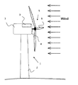
- FIG. 1 a schematic side view of a wind turbine.
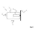
- FIG. 2 a schematic top view of a wind turbine.
- FIG. 3 a schematic view of an aspect of the invention.
- FIG. 4 a schematic view of a pole-zero placement for the band-stop filter implementation in the z-domain.
- FIG. 5 a schematic view of the effect of changing the IIR filter
- FIG. 6 a schematic view of an apparatus according to the invention.
- FIG. 7 a schematic view of graph illustrating aspects of the invention.
- FIG. 1 shows a wind turbine 1 with a tower 2 and a nacelle 3 .
- the axle 4 has a rotor 5 with three blades 6 , as is common for modern wind turbines although the wind turbine 1 could have any number of blades.
- wind When wind is present, it stimulates the rotor 5 which then starts to rotate.
- the rotational energy taken from the wind energy will be converted to electrical energy in a generator in the nacelle 3 .
- the wind turbine 1 can then transmit the electricity to the utility grid.
- FIG. 2 shows the wind turbine from above, where the nacelle 3 and the rotor 5 can be seen.
- the wind turbine 1 can start to oscillate.
- the rotation of the rotor generates a frequency component corresponding to the rotor speed.
- the frequency is called the 1P-frequency.
- the 1P-frequency is usually caused by an unbalance between the blades for instance if their weights differ or difference in their pitch calibration. Due to the use of three blades, there is also generated a frequency component corresponding to three times the rotor speed. This frequency is called the 3P-frequency. This is generated because the speed of the wind is larger at an increased height.
- the present invention provides an apparatus and a method for determining the resonant frequency of the tower.
- the oscillation can have a fore-aft component and a sideways component.
- the fore-aft component is illustrated by the arrows 7 and the sideways component is illustrated with the arrows 8 .
- the wind turbine 1 has a measuring module 9 having a accelerometer which is positioned in the nacelle, that can measure the oscillations of the wind turbine 1 . These measurements can be used to determine the resonant frequency of the tower 2 , this can be done by using the sideways and/or the fore-aft acceleration measurement and/or by combining the measurements.
- FIG. 3 is a sketch of an embodiment of the invention that is able to estimate the natural frequency of a wind turbine tower.
- a measuring module 9 has an accelerometer which establishes acceleration values of the tower 2 by continuously measuring the acceleration.
- the inventor has realised that it is possible to estimate the natural frequency of a wind turbine tower from the signal received from the sideways oscillations of the tower alone. This is because the natural oscillation seams to be more distinct in that signal compared to the fore-aft signal.
- the signal from the measuring module 9 is transmitted to the filter module 10 that attenuates a band of frequencies established by the adaptive algorithm module 11 .
- the filtered signal output of the filter module 10 is transmitted to the adaptive algorithm module 11 .
- the adaptive algorithm module 11 can receive an unaltered signal directly from the accelerometer 9 , in the present embodiment only the signal from the filter module 10 is used.
- the filtered signal from the filter module 10 can be used to determine the performance of the apparatus for estimating a resonant frequency of a wind turbine tower. By evaluating the output of the filter module 10 with the filter on and with the filter off the effect of the filter module 10 can be established.
- the adaptive algorithm module 11 establishes the frequency that has the highest energy contribution to the signal and communicates that frequency to the filter module 10 .
- the filter module 10 attenuates a band or interval of frequencies centred at that frequency.
- the adaptive algorithm module 11 also communicates the frequency to the estimating module 12 .
- the estimating module 12 estimates the natural frequency of the tower.
- the established frequency can in some cases, drift over time but will stay close to the true resonant frequency of the tower, statistical methods can be used to evaluate the changes in the established frequency to find a estimate of the natural resonant frequency of the wind turbine tower.
- the natural frequency is estimated as the frequency established by the adaptive algorithm module 11 .
- these frequencies can be removed from the signal transmitted to the module 11 .
- This can be done by the use of a rotor rotation module 13 that establishes the rotational speed of the rotor and thus its rotor frequency.
- the frequencies in a band around the rotor frequency are attenuated to remove the 1P frequency and the band around three times the rotor frequency is attenuated which will remove the 3P frequency from the signal.
- Attenuating the 1P and the 3P frequency can be done with the knowledge of the rotor rotational frequency, thus, without the need of an analysis of the signal.
- the natural frequency of the tower will be the most significant frequency.
- the removal of the 1P and the 3P frequencies is done in the filter module 10 but it can be done anywhere, for example be a part of the adaptive algorithm.
- Some wind turbines are designed to have a constant rotor speed in which case, the 1P and 3P filter can be a simple static filter attenuating frequencies around the predefined rotor frequency.
- an adaptive LMS algorithm in the adaptive algorithm module 11 is used to minimise the signal energy by the use of a band-stop filter in the filter module 10 .
- the band-stop filter is implemented using an IIR (Infinite impulse response) filter.
- IIR Infinite impulse response
- the band-stop filter will dampen a narrow band of frequencies around a centre frequency which will be the most significant frequency, established by the adaptive algorithm.
- FIG. 6 shows an apparatus 14 for estimating a resonant frequency of a wind turbine tower.
- the apparatus 14 is a simpler embodiment than the schematic view of the invention shown in FIG. 3 .
- the apparatus 14 comprises a measuring module 9 , wherein a accelerometer establishes acceleration values. These values are forwarded to the filter module 10 which attenuates frequencies in a band around a centre frequency.
- the centre frequency is established by the adaptive algorithm module 11 by receiving the filtered signal from the filter module 10 and then minimise the energy in the signal by adjusting the centre frequency.
- the centre frequency is then forwarded to the filter module 10 .
- the resonant frequency estimating module 12 receives the data regarding the centre frequency and then establishes the resonant frequency of 1 wind turbine tower.
- the adaptive LMS algorithm can be based on recursively or updating the estimate of the resonant frequency of a wind turbine tower by use of the derivative of a cost function.
- the cost function can be defined as the difference between the desired filter response and the actual filter response, as shown in equation 1.
- the update equation used to find an estimate can be based on the derivative of the cost function and a step size ( ⁇ ) as shown in equation 2.
- w ⁇ ⁇ ( n + 1 ) w ⁇ ⁇ ( n ) - ⁇ ⁇ ⁇ J ⁇ ( n ) ⁇ w ⁇ ⁇ ( n ) , Equation ⁇ ⁇ 2
- ⁇ (n) is a vector containing the parameters to optimize.
- the implementation has to ensure the stability. This can be done by choosing a filter structure where the poles are placed within the unit circle in the z-domain.
- the implementation of the IIR filter stop-band of the present embodiment is shown in equation 3.
- H ⁇ ( z ) 1 - 2 ⁇ cos ⁇ ( ⁇ ) ⁇ z - 1 + z - 2 1 - 2 ⁇ r ⁇ cos ⁇ ( ⁇ ) ⁇ z - 1 + r 2 ⁇ z - 2 , Equation ⁇ ⁇ 3
- the parameter r is giving the filter characteristic as a compromise between the width and damping at the band-step while the parameter ⁇ gives the centre frequency in [rad] found with respect to the sample rate using equation 4.
- ⁇ 2 ⁇ ⁇ ⁇ f F S , Equation ⁇ ⁇ 4
- f is the frequency in [Hz]
- ⁇ is the frequency in [rad]
- F S is the sample rate in [Hz].
- the filter implementation in the z-domain places a complex conjugate zero pair on the unit circle and a complex conjugate pole pair within the unit circle as illustrated on FIG. 4 .
- the parameter r determines the frequency characteristics of the filter.
- the chosen parameter makes the filter commonly adapt successfully to the most significant frequency within ⁇ 0.5 Hz of the given centre frequency. However, the performance will vary according to the SNR (Signal-to-noise ratio) and characteristics of the excitation signal.
- Equation 5 The implementation of the chosen IIR filter is shown in equation 5, expressed as a function in the time domain.
- y ( n ) x ( n ) ⁇ 2 ⁇ cos( ⁇ ) ⁇ x ( n ⁇ 1)+ x ( n ⁇ 2)+2 ⁇ r ⁇ cos( ⁇ ) ⁇ y ( n ⁇ 1) ⁇ r 2 ⁇ y ( n ⁇ 2), Equation 5
- Equation 5 can be used as the general expression of the update equation for an adaptive LMS algorithm applied to an IIR filter.
- the equation is simplified to one equation as only one parameter is to be optimized, namely ⁇ , accordingly:
- Equation ⁇ ⁇ 6 ⁇ is consistent with the frequency of the IIR filter shown in equation 5 and as mentioned, it is the only parameter to be estimated.
- the implementation of the differentiation can be done by dividing the difference in y(n) with the difference in ⁇ (n) as shown in Equation 8.
- ⁇ y ⁇ ( n ) ⁇ ⁇ ⁇ ( n ) y ⁇ ( n ) - y ⁇ ( n - 1 ) ⁇ ⁇ ( n ) - ⁇ ⁇ ( n - 1 ) Equation ⁇ ⁇ 8
- the found partial derivative depends on partial derivatives of y(n ⁇ 1) with respect to ⁇ (n).
- the partial derivative can be calculated recursively assuming the change from ⁇ (n) to ⁇ (n ⁇ 1) is small enough making the two assumptions in equation 10 valid.
- ⁇ y ⁇ ( n ) ⁇ ⁇ ⁇ ( n ) 2 ⁇ sin ⁇ ( ⁇ ) ⁇ x ⁇ ( n - 1 ) + 2 ⁇ r ⁇ cos ⁇ ( ⁇ ) ⁇ ⁇ y ⁇ ( n - 1 ) ⁇ ⁇ ⁇ ( n - 1 ) - 2 ⁇ r ⁇ sin ⁇ ( ⁇ ) ⁇ y ⁇ ( n - 1 ) - r 2 ⁇ ⁇ y ⁇ ( n - 2 ) ⁇ ⁇ ⁇ ( n - 2 ) Equation ⁇ ⁇ 12
- ⁇ ⁇ ( n + 1 ) ⁇ ⁇ ( n ) + ⁇ ⁇ y ⁇ ( n ) ⁇ ⁇ y ⁇ ( n ) ⁇ ⁇ ⁇ ( n ) , Equation ⁇ ⁇ 13 where y(n) is found from equation 12.
- the algorithm used in the present embodiment is now presented. It is quite simple and requires only a few calculations during every single iteration. An initial guess can be introduced to help the algorithm converge faster and make the likelihood of errors smaller. The initial guess in the present case is chosen to be 0.
- the steps in the adaptive LMS IIR filter can be expressed as:
- the complexity of the adaptive LMS algorithm according to the present embodiment of the invention is relatively simple.
- the IIR filter contains two parameters where the parameter r has been described above and visualized in FIG. 5 which shows the change in filter characteristics when changing the parameter r.
- the filter parameter ⁇ changes the centre frequency of the filter and this is the adaptively estimated parameter.
- the step size ⁇ can be chosen to be above the highest expected amplitudes of the filter response to guarantee the stability.
- non-normalized adaptive LMS algorithm is chosen which allows the algorithm to take larger steps when the oscillations are stronger making the algorithm adapt stronger when the signal holds more energy.
- the present embodiment uses an adaptive algorithm to minimise the signal energy of measured acceleration values from a wind turbine by applying a variable filter.
- FIG. 7 is a graphic illustration of the invention in a frequency-energy diagram.
- a graph 17 showing the frequencies of the measurements of the accelerometer 9 .
- the resonant frequency of the wind turbine tower 2 can be seen as the peak 15 .
- This resonant peak 15 can be the resonant frequency.
- the adaptive filter applied to the signal is shown as the filter graph 16 . As can be seen the filter attenuates the frequencies around the peak 15 and hereby attenuating the resonant frequency.
Landscapes
- Engineering & Computer Science (AREA)
- Chemical & Material Sciences (AREA)
- Life Sciences & Earth Sciences (AREA)
- Physics & Mathematics (AREA)
- Sustainable Energy (AREA)
- Combustion & Propulsion (AREA)
- Mechanical Engineering (AREA)
- General Engineering & Computer Science (AREA)
- Sustainable Development (AREA)
- General Physics & Mathematics (AREA)
- Acoustics & Sound (AREA)
- Health & Medical Sciences (AREA)
- Analytical Chemistry (AREA)
- Biochemistry (AREA)
- General Health & Medical Sciences (AREA)
- Immunology (AREA)
- Pathology (AREA)
- Wind Motors (AREA)
Abstract
Description
where d(n) is the desired response, y(n) is the actual response and e(n) is the error signal.
where ŵ(n) is a vector containing the parameters to optimize.
where f is the frequency in [Hz], φ is the frequency in [rad] and FS is the sample rate in [Hz].
y(n)=x(n)−2·cos(φ)·x(n−1)+x(n−2)+2·r·cos(φ)·y(n−1)−r 2 ·y(n−2),
φ is consistent with the frequency of the IIR filter shown in
where y(n) is found from
-
- 1) Find the initial condition for the filter.
- 2) Iteratively calculate the following steps.
- a. Calculate the filter output y(n).
- b. Calculate the filter derivative
-
-
- c. Calculate the new angle φ(n+1) using
equation 13 - d. Output the angle after each iteration.
- c. Calculate the new angle φ(n+1) using
-
| TABLE 1 |
| Computational complexity for the adaptive LMS algorithm on an IIR filter |
| Steps | Multiplications | Additions | Sine/ | Division |
| A | ||||
| 7 | 4 | 2 | 0 | |
| |
10 | 3 | 3 | 0 |
| |
3 | 2 | 0 | 1 |
| D | — | — | — | — |
| Total | 20 | 9 | 5 | 1 |
- 1 wind turbine
- 2 tower
- 3 nacelle
- 4 axle
- 5 rotor
- 6 blades
- 7 fore-aft
- 8 sideways
- 9 measuring module
- 10 filter module
- 11 adaptive algorithm module
- 12 resonant frequency estimating module
- 13 rotor rotation module
- 14 apparatus for estimating a resonant frequency of a wind turbine tower
- 15 resonant peak
- 16 filter graph
- 17 frequency graph
Claims (19)
Applications Claiming Priority (1)
| Application Number | Priority Date | Filing Date | Title |
|---|---|---|---|
| PCT/DK2010/050340 WO2012079574A1 (en) | 2010-12-15 | 2010-12-15 | Apparatus for estimating a resonant frequency of a wind turbine tower |
Publications (2)
| Publication Number | Publication Date |
|---|---|
| US20140012516A1 US20140012516A1 (en) | 2014-01-09 |
| US8880357B2 true US8880357B2 (en) | 2014-11-04 |
Family
ID=44542886
Family Applications (1)
| Application Number | Title | Priority Date | Filing Date |
|---|---|---|---|
| US13/993,228 Expired - Fee Related US8880357B2 (en) | 2010-12-15 | 2010-12-15 | Apparatus for estimating a resonant frequency of a wind turbine tower |
Country Status (3)
| Country | Link |
|---|---|
| US (1) | US8880357B2 (en) |
| EP (1) | EP2652467A1 (en) |
| WO (1) | WO2012079574A1 (en) |
Cited By (1)
| Publication number | Priority date | Publication date | Assignee | Title |
|---|---|---|---|---|
| US11635062B2 (en) | 2018-11-07 | 2023-04-25 | General Electric Renovables Espana, S.L. | Wind turbine and method to determine modal characteristics of the wind turbine in a continuous manner |
Families Citing this family (3)
| Publication number | Priority date | Publication date | Assignee | Title |
|---|---|---|---|---|
| US9651443B2 (en) | 2014-06-06 | 2017-05-16 | General Electric Company | System and method for protecting rotary machines |
| CN110568081B (en) * | 2019-08-01 | 2022-05-31 | 北京建筑大学 | Ancient building damage testing device and method |
| DK181447B1 (en) * | 2021-11-19 | 2024-01-23 | Shanghai electric wind power group co ltd | Controller, method, apparatus, and computer program product for a wind turbine |
Family Cites Families (5)
| Publication number | Priority date | Publication date | Assignee | Title |
|---|---|---|---|---|
| US7309930B2 (en) * | 2004-09-30 | 2007-12-18 | General Electric Company | Vibration damping system and method for variable speed wind turbines |
| EP2115299B1 (en) * | 2006-12-28 | 2011-03-16 | Clipper Windpower, Inc. | Wind turbine damping of tower resonant motion and symmetric blade motion using estimation methods |
| DE102007063082B4 (en) * | 2007-12-21 | 2010-12-09 | Repower Systems Ag | Method for operating a wind energy plant |
| DK2103915T3 (en) | 2008-03-17 | 2017-02-20 | Siemens Ag | Device and method for determining a resonant frequency of a wind turbine tower |
| AU2010220551B2 (en) * | 2009-03-02 | 2013-10-10 | Suzlon Energy Gmbh | Method for monitoring wind turbines |
-
2010
- 2010-12-15 EP EP10803220.2A patent/EP2652467A1/en not_active Withdrawn
- 2010-12-15 US US13/993,228 patent/US8880357B2/en not_active Expired - Fee Related
- 2010-12-15 WO PCT/DK2010/050340 patent/WO2012079574A1/en active Application Filing
Cited By (1)
| Publication number | Priority date | Publication date | Assignee | Title |
|---|---|---|---|---|
| US11635062B2 (en) | 2018-11-07 | 2023-04-25 | General Electric Renovables Espana, S.L. | Wind turbine and method to determine modal characteristics of the wind turbine in a continuous manner |
Also Published As
| Publication number | Publication date |
|---|---|
| EP2652467A1 (en) | 2013-10-23 |
| WO2012079574A1 (en) | 2012-06-21 |
| US20140012516A1 (en) | 2014-01-09 |
Similar Documents
| Publication | Publication Date | Title |
|---|---|---|
| US8880357B2 (en) | Apparatus for estimating a resonant frequency of a wind turbine tower | |
| US8511988B2 (en) | Monitoring of blade frequencies of a wind turbine | |
| US20100111693A1 (en) | Wind turbine damping of tower resonant motion and symmetric blade motion using estimation methods | |
| US8039981B2 (en) | Monitoring of blade frequencies of a wind turbine | |
| KR20190122840A (en) | Method for determining available power of a wind farm, and associated wind farms | |
| CN105275742B (en) | A kind of control method of Wind turbines adaptive environment | |
| EP1978246A1 (en) | Method of reducing an unbalance in a wind turbine rotor and device for performing the method | |
| CN109642542B (en) | Diagnostic system and method for a wind turbine | |
| US20110153099A1 (en) | Method and system for controlling a wind power plant comprising a number of wind turbine generators | |
| CN103321854A (en) | Vibration control method for wind generator set tower | |
| EP2472238A1 (en) | Determination of a vibrational frequency of a wind turbine rotor blade with a sensor device being placed at a structural component being assigned to and/or being part of the rotor | |
| KR101822535B1 (en) | Tilt damping of a floating wind turbine | |
| CN107589299B (en) | Electric power signal synchronous phasor measuring method based on multi-frequency the measures model | |
| EP3225838A1 (en) | Method and arrangement for performing a wind direction measurement | |
| Bhui et al. | Estimation of inherent governor dead-band and regulation using unscented Kalman filter | |
| CN102410139B (en) | Determine the method and apparatus of the common blade frequencies of rotor and the method for operation wind turbine | |
| US20190292933A1 (en) | Power source, adjusting power instructing apparatus, method, and recording medium for changing adjusting power | |
| CN109521275A (en) | A kind of synchronized phasor determines method, system, device and readable storage medium storing program for executing | |
| CN110244151A (en) | A kind of synchronous phasor measuring method, system and associated component | |
| RU2543367C1 (en) | Energy loss determining method | |
| CN112012884B (en) | Control method and device of wind generating set | |
| US20200371142A1 (en) | Power system detection of sustained oscillations based on synchrophasor frequency measurements | |
| WO2020098892A1 (en) | Wind turbine noise masking | |
| US20230178990A1 (en) | System and method for automated tuning/configuring of a power system stabilizer (pss) in a digital excitation control system | |
| Malec et al. | Comparison of low frequency signals emitted by wind turbines of two different generator types |
Legal Events
| Date | Code | Title | Description |
|---|---|---|---|
| AS | Assignment |
Owner name: KK-ELECTRONIC A/S, DENMARK Free format text: ASSIGNMENT OF ASSIGNORS INTEREST;ASSIGNOR:NIELSEN, RASMUS;REEL/FRAME:031049/0074 Effective date: 20130809 |
|
| AS | Assignment |
Owner name: KK WIND SOLUTIONS A/S, DENMARK Free format text: CHANGE OF NAME;ASSIGNOR:KK-ELECTRONIC A/S;REEL/FRAME:036581/0255 Effective date: 20140922 |
|
| FEPP | Fee payment procedure |
Free format text: MAINTENANCE FEE REMINDER MAILED (ORIGINAL EVENT CODE: REM.) |
|
| LAPS | Lapse for failure to pay maintenance fees |
Free format text: PATENT EXPIRED FOR FAILURE TO PAY MAINTENANCE FEES (ORIGINAL EVENT CODE: EXP.); ENTITY STATUS OF PATENT OWNER: LARGE ENTITY |
|
| STCH | Information on status: patent discontinuation |
Free format text: PATENT EXPIRED DUE TO NONPAYMENT OF MAINTENANCE FEES UNDER 37 CFR 1.362 |
|
| FP | Lapsed due to failure to pay maintenance fee |
Effective date: 20181104 |