US8879100B2 - Image forming system, image forming device, and non-transitory computer readable medium for updating information based upon a usage count - Google Patents
Image forming system, image forming device, and non-transitory computer readable medium for updating information based upon a usage count Download PDFInfo
- Publication number
- US8879100B2 US8879100B2 US13/448,917 US201213448917A US8879100B2 US 8879100 B2 US8879100 B2 US 8879100B2 US 201213448917 A US201213448917 A US 201213448917A US 8879100 B2 US8879100 B2 US 8879100B2
- Authority
- US
- United States
- Prior art keywords
- image forming
- unit
- user
- information
- forming device
- Prior art date
- Legal status (The legal status is an assumption and is not a legal conclusion. Google has not performed a legal analysis and makes no representation as to the accuracy of the status listed.)
- Active, expires
Links
Images


Classifications
-
- H—ELECTRICITY
- H04—ELECTRIC COMMUNICATION TECHNIQUE
- H04N—PICTORIAL COMMUNICATION, e.g. TELEVISION
- H04N1/00—Scanning, transmission or reproduction of documents or the like, e.g. facsimile transmission; Details thereof
- H04N1/00127—Connection or combination of a still picture apparatus with another apparatus, e.g. for storage, processing or transmission of still picture signals or of information associated with a still picture
- H04N1/00344—Connection or combination of a still picture apparatus with another apparatus, e.g. for storage, processing or transmission of still picture signals or of information associated with a still picture with a management, maintenance, service or repair apparatus
-
- G—PHYSICS
- G06—COMPUTING; CALCULATING OR COUNTING
- G06F—ELECTRIC DIGITAL DATA PROCESSING
- G06F3/00—Input arrangements for transferring data to be processed into a form capable of being handled by the computer; Output arrangements for transferring data from processing unit to output unit, e.g. interface arrangements
- G06F3/12—Digital output to print unit, e.g. line printer, chain printer
- G06F3/1201—Dedicated interfaces to print systems
- G06F3/1202—Dedicated interfaces to print systems specifically adapted to achieve a particular effect
- G06F3/1222—Increasing security of the print job
-
- G—PHYSICS
- G06—COMPUTING; CALCULATING OR COUNTING
- G06F—ELECTRIC DIGITAL DATA PROCESSING
- G06F3/00—Input arrangements for transferring data to be processed into a form capable of being handled by the computer; Output arrangements for transferring data from processing unit to output unit, e.g. interface arrangements
- G06F3/12—Digital output to print unit, e.g. line printer, chain printer
- G06F3/1201—Dedicated interfaces to print systems
- G06F3/1223—Dedicated interfaces to print systems specifically adapted to use a particular technique
- G06F3/1237—Print job management
- G06F3/1239—Restricting the usage of resources, e.g. usage or user levels, credit limit, consumables, special fonts
-
- G—PHYSICS
- G06—COMPUTING; CALCULATING OR COUNTING
- G06F—ELECTRIC DIGITAL DATA PROCESSING
- G06F3/00—Input arrangements for transferring data to be processed into a form capable of being handled by the computer; Output arrangements for transferring data from processing unit to output unit, e.g. interface arrangements
- G06F3/12—Digital output to print unit, e.g. line printer, chain printer
- G06F3/1201—Dedicated interfaces to print systems
- G06F3/1223—Dedicated interfaces to print systems specifically adapted to use a particular technique
- G06F3/1237—Print job management
- G06F3/1273—Print job history, e.g. logging, accounting, tracking
-
- G—PHYSICS
- G06—COMPUTING; CALCULATING OR COUNTING
- G06F—ELECTRIC DIGITAL DATA PROCESSING
- G06F3/00—Input arrangements for transferring data to be processed into a form capable of being handled by the computer; Output arrangements for transferring data from processing unit to output unit, e.g. interface arrangements
- G06F3/12—Digital output to print unit, e.g. line printer, chain printer
- G06F3/1201—Dedicated interfaces to print systems
- G06F3/1278—Dedicated interfaces to print systems specifically adapted to adopt a particular infrastructure
- G06F3/1285—Remote printer device, e.g. being remote from client or server
- G06F3/1288—Remote printer device, e.g. being remote from client or server in client-server-printer device configuration
-
- H—ELECTRICITY
- H04—ELECTRIC COMMUNICATION TECHNIQUE
- H04N—PICTORIAL COMMUNICATION, e.g. TELEVISION
- H04N1/00—Scanning, transmission or reproduction of documents or the like, e.g. facsimile transmission; Details thereof
- H04N1/00832—Recording use, e.g. counting number of pages copied
-
- G—PHYSICS
- G06—COMPUTING; CALCULATING OR COUNTING
- G06F—ELECTRIC DIGITAL DATA PROCESSING
- G06F3/00—Input arrangements for transferring data to be processed into a form capable of being handled by the computer; Output arrangements for transferring data from processing unit to output unit, e.g. interface arrangements
- G06F3/12—Digital output to print unit, e.g. line printer, chain printer
- G06F3/1201—Dedicated interfaces to print systems
- G06F3/1223—Dedicated interfaces to print systems specifically adapted to use a particular technique
- G06F3/1237—Print job management
- G06F3/1267—Job repository, e.g. non-scheduled jobs, delay printing
-
- G—PHYSICS
- G06—COMPUTING; CALCULATING OR COUNTING
- G06F—ELECTRIC DIGITAL DATA PROCESSING
- G06F3/00—Input arrangements for transferring data to be processed into a form capable of being handled by the computer; Output arrangements for transferring data from processing unit to output unit, e.g. interface arrangements
- G06F3/12—Digital output to print unit, e.g. line printer, chain printer
- G06F3/1201—Dedicated interfaces to print systems
- G06F3/1278—Dedicated interfaces to print systems specifically adapted to adopt a particular infrastructure
- G06F3/1291—Pool of printer devices: self-managing printing devices in a network, e.g. without a server
-
- H—ELECTRICITY
- H04—ELECTRIC COMMUNICATION TECHNIQUE
- H04N—PICTORIAL COMMUNICATION, e.g. TELEVISION
- H04N1/00—Scanning, transmission or reproduction of documents or the like, e.g. facsimile transmission; Details thereof
- H04N1/32—Circuits or arrangements for control or supervision between transmitter and receiver or between image input and image output device, e.g. between a still-image camera and its memory or between a still-image camera and a printer device
- H04N1/32101—Display, printing, storage or transmission of additional information, e.g. ID code, date and time or title
- H04N1/32106—Display, printing, storage or transmission of additional information, e.g. ID code, date and time or title separate from the image data, e.g. in a different computer file
- H04N1/32122—Display, printing, storage or transmission of additional information, e.g. ID code, date and time or title separate from the image data, e.g. in a different computer file in a separate device, e.g. in a memory or on a display separate from image data
-
- H—ELECTRICITY
- H04—ELECTRIC COMMUNICATION TECHNIQUE
- H04N—PICTORIAL COMMUNICATION, e.g. TELEVISION
- H04N2201/00—Indexing scheme relating to scanning, transmission or reproduction of documents or the like, and to details thereof
- H04N2201/0008—Connection or combination of a still picture apparatus with another apparatus
- H04N2201/0034—Details of the connection, e.g. connector, interface
- H04N2201/0037—Topological details of the connection
- H04N2201/0039—Connection via a network
-
- H—ELECTRICITY
- H04—ELECTRIC COMMUNICATION TECHNIQUE
- H04N—PICTORIAL COMMUNICATION, e.g. TELEVISION
- H04N2201/00—Indexing scheme relating to scanning, transmission or reproduction of documents or the like, and to details thereof
- H04N2201/0077—Types of the still picture apparatus
- H04N2201/0082—Image hardcopy reproducer
-
- H—ELECTRICITY
- H04—ELECTRIC COMMUNICATION TECHNIQUE
- H04N—PICTORIAL COMMUNICATION, e.g. TELEVISION
- H04N2201/00—Indexing scheme relating to scanning, transmission or reproduction of documents or the like, and to details thereof
- H04N2201/32—Circuits or arrangements for control or supervision between transmitter and receiver or between image input and image output device, e.g. between a still-image camera and its memory or between a still-image camera and a printer device
- H04N2201/3201—Display, printing, storage or transmission of additional information, e.g. ID code, date and time or title
- H04N2201/3204—Display, printing, storage or transmission of additional information, e.g. ID code, date and time or title of data relating to a user, sender, addressee, machine or electronic recording medium
- H04N2201/3205—Display, printing, storage or transmission of additional information, e.g. ID code, date and time or title of data relating to a user, sender, addressee, machine or electronic recording medium of identification information, e.g. name or ID code
-
- H—ELECTRICITY
- H04—ELECTRIC COMMUNICATION TECHNIQUE
- H04N—PICTORIAL COMMUNICATION, e.g. TELEVISION
- H04N2201/00—Indexing scheme relating to scanning, transmission or reproduction of documents or the like, and to details thereof
- H04N2201/32—Circuits or arrangements for control or supervision between transmitter and receiver or between image input and image output device, e.g. between a still-image camera and its memory or between a still-image camera and a printer device
- H04N2201/3201—Display, printing, storage or transmission of additional information, e.g. ID code, date and time or title
- H04N2201/3274—Storage or retrieval of prestored additional information
Definitions
- the present invention relates to an image forming system, an image forming device, and a non-transitory computer readable medium.
- a technique of storing image data designated by a user in a print server device so that the image data may be accessed from plural image forming devices is known.
- an image forming system including: plural image forming devices; a first storage unit that stores user information for identifying a user and device information indicating an image forming device included in the plural image forming devices in a correlated manner; a transmitting device that transmits image data to an image forming device correlated with the user information indicated by the device information stored in the first storage unit; a second storage unit that is provided in each of the image forming devices and stores the image data transmitted from the transmitting device; a receiving unit that is provided in each of the image forming devices and receives an input of the user information; a first acquiring unit that is provided in each of the image forming devices and acquires image data corresponding to the user information from an image forming device correlated with the input user information indicated by the device information stored in the first storage unit; an image forming unit that is provided in each of the image forming devices and forms an image corresponding to the image data acquired by the first acquiring unit; a recording unit that is provided in each of the image forming devices and
- FIG. 1 is a schematic diagram showing the configuration of an image forming system according to a first exemplary embodiment
- FIG. 2 is a diagram showing a hardware configuration of a distribution server device
- FIG. 3 is a diagram showing an example of user information stored in the distribution server device
- FIG. 4 is a diagram showing a hardware configuration of a client device
- FIG. 5 is a diagram showing an example of information set to a printer driver
- FIG. 6 is a diagram showing a hardware configuration of an image forming device
- FIG. 7 is a diagram showing an example of user information stored in the image forming device.
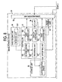
- FIG. 8 is a diagram showing the functional configurations of the image forming device according to the first exemplary embodiment
- FIG. 9 is a diagram showing the functional configurations of the distribution server device according to the first exemplary embodiment.
- FIG. 10 is a sequence chart showing a print operation
- FIG. 11 is a flowchart showing a user authentication process
- FIG. 12 is a diagram showing an example of an image data list
- FIG. 13 is a sequence chart showing a user information updating operation according to the first exemplary embodiment
- FIG. 14 is a diagram showing an example of recorded information
- FIG. 15 is a diagram showing an example of user information after updating
- FIG. 16 is a diagram showing the functional configurations of an image forming device according to a second exemplary embodiment
- FIG. 17 is a sequence chart showing a user information updating operation according to the second exemplary embodiment.
- FIG. 18 is a diagram showing the functional configurations of a distribution server device according to a third exemplary embodiment
- FIG. 19 is a sequence chart showing a user information updating operation according to the third exemplary embodiment.
- FIG. 20 is a diagram showing an example of a log
- FIG. 21 is a flowchart showing an user information updating process
- FIG. 22 is a diagram showing an example of total information.
- FIG. 1 is a schematic diagram showing the configuration of an image forming system 1 according to the first exemplary embodiment.
- the image forming system 1 includes a distribution server device 10 , a client device 20 , and image forming devices 30 A, 30 B, and 30 C.
- the distribution server device 10 , the client device 20 , and the image forming devices 30 A, 30 B, and 30 C are connected to each other via a communication line 2 .
- the image forming system 1 has a structure such that a user may store image data in any of the image forming devices 30 and form an image corresponding to the image data using any image forming device 30 .
- the image forming devices 30 A, 30 B, and 30 C may sometimes be collectively referred to as “image forming device 30 ” when they need not be distinguished from each other.
- FIG. 2 is a diagram showing a hardware configuration of the distribution server device 10 .
- the distribution server device 10 includes a central processing unit (CPU) 11 , a memory 12 , a communication unit 13 , a storage unit 14 , an operation unit 15 , and a display 16 .
- the CPU 11 controls each unit of the distribution server device 10 by executing a program stored in the memory 12 .
- the communication unit 13 is a communication interface connected to the communication line 2 .
- the distribution server device 10 communicates with the client device 20 or the image forming device 30 using the communication unit 13 .
- the storage unit 14 is a storage device such as a hard disk. User information 41 is stored in the storage unit 14 .
- the storage unit 14 is used as a first storage unit.
- the operation unit 15 includes a keyboard and a mouse, for example.
- the operation unit 15 is used for operating the distribution server device 10 .
- the display 16 is a display device such as a liquid crystal display.
- FIG. 3 is a diagram showing an example of the user information 41 .
- a user ID is correlated with plural spooler information.
- the user ID is information for identifying a user.
- the spooler information is information indicating the image forming device 30 in which image data is stored.
- IP Internet protocol
- the spooler information “spoolerA,” “spoolerB,” and “spoolerC” shown in FIG. 3 indicate the image forming devices 30 A, 30 B, and 30 C, respectively.
- a priority order is allocated to the spooler information.
- spooler information to which the priority order “1” is allocated is referred to as “primary spooler information,” and spooler information to which the priority order “2” is allocated is referred to as “secondary spooler information.”
- the user information 41 When the user information 41 is created, two spooler information randomly selected from “spoolerA,” “spoolerB,” and “spoolerC,” for example, are allocated to each user ID. In this case, one priority order randomly selected from the priority orders “1” and “2” is also correlated with each spooler information.
- primary spooler information “spoolerA” and secondary spooler information “spoolerC” are correlated with the user ID “user001.” This means that image data corresponding to the user ID “user001” are stored in the image forming device 30 A or the image forming device 30 C. In this case, the image forming device 30 A is used preferentially than the image forming device 30 C.
- FIG. 4 is a diagram showing a hardware configuration of the client device 20 .
- the client device 20 includes a CPU 21 , a memory 22 , a communication unit 23 , a storage unit 24 , an operation unit 25 , and a display 26 .
- the CPU 21 controls each unit of the client device 20 by executing a program stored in the memory 22 .
- the communication unit 23 is a communication interface connected to the communication line 2 .
- the client device 20 communicates with the distribution server device 10 or the image forming device 30 using the communication unit 23 .
- the storage unit 24 is a storage device such as a hard disk.
- a printer driver 42 is stored in the storage unit 24 .
- the printer driver 42 is a program having a function of controlling the image forming device 30 .
- the operation unit 25 includes a keyboard and a mouse, for example.
- the operation unit 25 is used for operating the client device 20 .
- the display 26 is a display device such as a liquid crystal display.
- FIG. 5 is a diagram showing an example of the information set in the printer driver 42 .
- the printer driver 42 the user ID “user001,” the primary spooler information “spoolerA,” and the secondary spooler information “spoolerC” included in the user information 41 shown in FIG. 3 are set. Only the primary spooler information and the secondary spooler information are set in the printer driver 42 , and spooler information to which the priority order “3” is allocated is not set in the printer driver 42 .
- FIG. 6 is a diagram showing a hardware configuration of the image forming device 30 .
- the image forming device 30 includes a controller 31 , a communication unit 32 , a storage unit 33 , a user interface (UI) unit 34 , an image forming unit 35 , and a card reading unit 36 .
- the controller 31 controls each unit of the image forming device 30 .
- the controller 31 includes a CPU and a memory, for example.
- the CPU realizes the function of the controller 31 by executing a program stored in the memory.
- the communication unit 32 is a communication interface connected to the communication line 2 .
- the image forming device 30 communicates with the distribution server device 10 , the client device 20 , or the other image forming devices 30 using the communication unit 32 .
- the storage unit 33 is a storage device such as a hard disk or a flash memory.
- the storage unit 33 includes a storage area 37 in which the image data are stored.
- the storage unit 33 is used as a second storage unit.
- user information 41 a corresponding to the above-described user information 41 is stored in the storage unit 33 .
- the UI unit 34 includes a touch screen and an operation button, for example.
- the UI unit 34 is used for operating the image forming device 30 .
- the image forming unit 35 is an electrophotographic printer, for example.
- the image forming unit 35 forms (prints) an image corresponding to the image data on a medium such as a paper.
- the card reading unit 36 reads information stored in an integrated circuit (IC) card in a non-contact manner.
- the IC card is provided to a user in advance in order to perform authentication of the user.
- the user ID included in the above-described user information 41 is stored in the IC card.
- the image forming device 30 may include a configuration realizing the function of a scanner, a facsimile, and the like in addition to the above-described configuration. In the following description, when the configurations of the image forming devices 30 A, 30 B, and 30 C need to be distinguished from each other, characters “A,” “B,” and “C” will be added to reference symbols of the configurations
- FIG. 7 is a diagram showing an example of user information 41 a .
- the user information 41 a includes the same user ID and the same spooler information as the user information 41 shown in FIG. 3 . Only the primary spooler information and the secondary spooler information are included in the user information 41 a , and spooler information to which the priority order “3” is allocated is not included in the user information 41 a.
- FIG. 8 is a diagram showing the functional configurations of the image forming device 30 .
- Respective image forming devices 30 have the same functional configuration. In FIG. 8 , the functional configurations of one image forming device 30 are not illustrated for the other image forming device 30 .
- a receiving unit 301 is realized by the card reading unit 36 .
- a third acquiring unit 302 , a display controller 303 , a first acquiring unit 304 , an authenticating unit 305 , a recording unit 306 , and a specifying unit 307 are realized when the CPU in the controller 31 , for example, executes a program.
- These functional configurations of the image forming device 30 may be realized by a single program and may be realized by plural programs.
- FIG. 9 is a diagram showing a functional configuration of the distribution server device 10 .
- An updating unit 101 is realized when the CPU 11 executes a program.
- the client device 20 transmits image data corresponding to a user ID to the image forming device 30 indicated by the spooler information stored in the distribution server device 10 so as to be correlated with the user ID. Attribute information including information for identifying image data is appended to the image data.
- the spooler information is an example of device information indicating the image forming device 30 .
- the client device 20 is used as a transmitting device. Practically, the client device 20 transmits image data based on the information set in the printer driver 42 . However, as described above, the user ID and the spooler information included in the user information 41 stored in the distribution server device 10 are set in the printer driver 42 . Thus, it may be said that the client device 20 transmits image data based on the user information 41 stored in the distribution server device 10 .
- the receiving unit 301 receives the input of the user ID.
- the user ID is an example of identification information for identifying a user.
- the third acquiring unit 302 acquires attribute information appended to image data corresponding to an input user ID from the image forming device 30 indicated by the primary spooler information and the image forming device 30 indicated by the secondary spooler information among the plural spooler information stored in the distribution server device 10 so as to be correlated with the input user ID.
- the primary spooler information and the secondary spooler information are examples of the first device information. These spooler information are a predetermined number (two) of spooler information selected based on a priority order.
- the third acquiring unit 302 acquires the attribute information based on the user information 41 a stored in the storage unit 33 .
- the same user ID and the same spooler information as the user information 41 stored in the distribution server device 10 are included in the user information 41 a .
- the third acquiring unit 302 acquires the attribute information based on the user information 41 stored in the distribution server device 10 .
- the display controller 303 displays the attribute information acquired by the third acquiring unit 302 on the UI unit 34 .
- the UI unit 34 is used as a display.
- the first acquiring unit 304 acquires image data selected based on the attribute information displayed on the UI unit 34 .
- the authenticating unit 305 performs user authentication using the input user ID.
- the recording unit 306 records an authentication count of authentication performed using each of the input user IDs in the storage unit 33 .
- the authentication count is an example of the use history of the user.
- the authentication count is an authentication frequency calculated based on the authentication history of the user ID. That is, it may be said that the recording unit 306 records the authentication history and calculates the frequency of authentication performed using the user ID based on the authentication history.
- the specifying unit 307 specifies a user ID and an own device based on the authentication count recorded by the recording unit 306 when the authentication count corresponding to the user ID in the own device has reached a first threshold value and notifies the distribution server device 10 of spooler information indicating the specified user ID and own device. That is, the specifying unit 307 specifies a user ID and an own device when a condition that the authentication count of the own device corresponding to the user ID has reached a threshold value is satisfied.
- the updating unit 101 shown in FIG. 9 updates the spooler information of the user information 41 stored in the storage unit 14 so that the spooler information and the user ID notified from the image forming device 30 are stored in a correlated manner.
- FIG. 10 is a sequence chart showing a print operation of the image forming system 1 .
- the user operates the client device 20 to input a print instruction. Specifically, the user designates image data using the operation unit 25 and issues a print instruction. In this example, it is assumed that the user issues a print instruction by designating image data D 1 .
- the client device 20 Upon receiving a print instruction, the client device 20 transmits image data D 1 to the image forming device 30 based on the information set in the printer driver 42 (step S 11 ). Specifically, the user ID “user001,” the primary spooler information “spoolerA” and the secondary spooler information “spoolerC” are set in the printer driver 42 as shown in FIG. 5 . In this case, the CPU 21 appends the attribute information including the user ID “user001” to the image data D 1 . In this way, the image data D 1 is used as image data corresponding to the user ID “user001.” Moreover, in addition to the user ID, information such as a file name for specifying the image data D 1 is included in the attribute information.
- the CPU 21 controls the communication unit 23 to transmit the image data D 1 to the image forming device 30 A indicated by the primary spooler information “spoolerA.”
- the CPU 21 controls the communication unit 23 to transmit the image data D 1 to the image forming device 30 C indicated by the secondary spooler information “spoolerC.”
- the client device 20 transmits the image data corresponding to the user ID to the image forming device 30 which is available and indicated by spooler information having the highest priority order allocated thereto among the image forming devices 30 indicated by the spooler information set in the printer driver 42 .
- “available” means that image data may be stored in the image forming device 30 . Whether the image forming device 30 is available or not is determined, for example, by transmitting an echo request to the image forming device 30 and determining whether an echo response is returned from the image forming device 30 . When the image forming device 30 and the communication line 2 are operating properly, an echo response is returned from the image forming device 30 .
- an echo response is not returned from the image forming device 30 .
- the client device 20 determines that the image forming device 30 is an unavailable state.
- the image forming device 30 A is available.
- the image data D 1 is transmitted from the client device 20 to the image forming device 30 A.
- the image forming device 30 A Upon receiving the image data D 1 from the client device 20 , the image forming device 30 A stores the image data D 1 in a storage area 37 A of the storage unit 33 A (step S 12 ).
- the user moves to a place where one of the image forming devices 30 A, 30 B, and 30 C is located.
- the user may move to a place where the image forming device 30 usually used by the user is located.
- the user may move to a place where the nearby image forming device 30 is located.
- the user may move to a place where the image forming device 30 nearest to the present location of the user is located. That is, the user moves to the place of the image forming device 30 so that the user may use anyone of the image forming devices 30 A, 30 B, and 30 C.
- An authentication screen is displayed on the UI unit 34 of the image forming device 30 , and unless authentication is performed, the operation on the image forming device 30 is not received.
- the user performs authentication by passing an IC card thereof over a card reading unit 36 B in order to use the image forming device 30 B.
- the image forming device 30 B performs a user authentication process using the user ID (step S 13 ).
- FIG. 11 is a flowchart showing a user authentication process.
- a user ID “user001” is stored in the IC card.
- the card reading unit 36 B reads the user ID “user001” from the IC card (step S 131 ).
- a controller 31 B determines whether or not the user ID “user001” is included in the user information 41 a stored in the storage unit 33 B (step S 132 ). For example, when the user ID “user001” is not included in the user information 41 a (step S 132 : NO), the controller 31 B displays a message indicating authentication failure on the UI unit 34 B (step S 133 ), and this process ends. In this case, it is not possible for the user to use the image forming device 30 B.
- step S 132 when the user ID “user001” is included in the user information 41 a (step S 132 : YES), the controller 31 B authenticates the user as an authenticated user (step S 134 ), and the flow proceeds to the next step S 14 .
- the image forming device 30 B acquires the attribute information of image data corresponding to the user ID “user001” based on the user information 41 a stored in the storage unit 33 B. Specifically, as shown in FIG. 3 , in the user information 41 a , the primary spooler information “spoolerA” and the secondary spooler information “spoolerC” are correlated with the user ID “user001.” In this case, the controller 31 B controls the communication unit 32 B sends a request for the attribute information of image data corresponding to the user ID “user001” to the image forming device 30 A indicated by the primary spooler information “spoolerA” and the image forming device 30 C indicated by the secondary spooler information “spoolerC” (step S 14 of FIG. 10 ).
- the image forming devices 30 A and 30 C transmit the attribute information to the image forming device 30 B when the image forming devices 30 A and 30 C possess the attribute information requested from the image forming device 30 B (step S 15 ).
- the image data D 1 is stored in the storage unit 33 A of the image forming device 30 A.
- the attribute information including the user ID “user001” is appended to the image data D 1 .
- the controller 31 A reads the attribute information from the storage unit 33 A and controls the communication unit 32 A to transmit the attribute information to the image forming device 30 B.
- the image data D 2 corresponding to a user ID “user001” is stored in the storage unit 33 C of the image forming device 30 C.
- the controller 31 C reads the attribute information from the storage unit 33 C and controls the communication unit 32 C to transmit the attribute information to the image forming device 30 B.
- the image forming device 30 B receives these attribute information from the image forming devices 30 A and 30 C.
- FIG. 12 is a diagram showing an example of the image data list 50 .
- the attribute information of the image data D 1 acquired from the image forming device 30 A and the attribute information of the image data D 2 acquired from the image forming device 30 C are arranged in a line.
- a “PRINT” button 51 for receiving a print instruction is displayed on the UI unit 34 B together with the image data list 50 .
- the user select desired image data based on the image data list 50 displayed on the UI unit 34 and presses the “PRINT” button 51 . In this example, it is assumed that the image data D 1 is selected and the “PRINT” button 51 is pressed.
- the image forming device 30 B acquires the image data D 1 from the image forming device 30 in which the selected image data D 1 is stored. Specifically, the controller 31 B controls the communication unit 32 B to send a request for the image data D 1 to the image forming device 30 A which is an origin that transmits the attribute information of the image data D 1 (step S 17 ). The image forming device 30 A reads the image data D 1 requested from the image forming device 30 B from the storage unit 33 A and transmits the image data D 1 to the image forming device 30 B (step S 18 ). The image forming device 30 B receives the image data D 1 from the image forming device 30 A.
- the image forming device 30 B Upon acquiring the image data D 1 , the image forming device 30 B performs printing based on the image data D 1 (step S 19 ). Specifically, the controller 31 B supplies the image data D 1 to the image forming unit 35 B and forms an image corresponding to the image data D 1 . The image forming unit 35 B forms an image corresponding to the image data D 1 on a medium under the control of the controller 31 B.
- the user information 41 stored in the distribution server device 10 is updated depending on which image forming device 30 is frequently used by the user.
- FIG. 13 is a sequence chart showing an operation of updating the user information 41 .
- the image forming device 30 records an authentication count for each user ID.
- the controller 31 measures an authentication count of a user authentication process performed using each of the user IDs.
- the controller 31 does not measure an authentication count for a user ID in the user information 41 a stored in the storage unit 33 , which is correlated with spooler information indicating the own device.
- FIG. 14 is a diagram showing an example of the recording information 43 stored in the image forming device 30 B.
- “5” is recorded as the authentication count corresponding to the user ID “user001.” This indicates that the image forming device 30 B has performed the user authentication process “five times” using the user ID “user001.”
- This authentication count is reset once a day, for example. Alternatively, the authentication count may be reset once several days. In this case, the authentication count is measured every several days.
- the image forming device 30 specifies a user ID and an own device corresponding to the authentication count and notifies the distribution server device 10 of the spooler information indicating the user ID and the own device. Specifically, the controller 31 determines whether or not the authentication count included in the recording information 43 has reached a threshold value (step S 21 of FIG. 13 ). In this example, it is assumed that the threshold value is “5.”
- step S 21 NO
- the controller 31 B returns to step S 21 .
- the controller 31 B specifies the user ID “user001” and the image forming device 30 B (step S 22 ).
- the controller 31 B controls the communication unit 32 B to transmit update information including the user ID “user001” and the spooler information “spoolerB” indicating the own device to the distribution server device 10 (step S 23 ). In this way, the user ID specified in the image forming device 30 B and the spooler information indicating the image forming device 30 B are notified to the distribution server device 10 .
- the distribution server device 10 Upon receiving the update information from the image forming device 30 , the distribution server device 10 updates the user information 41 stored in the storage unit 14 at a predetermined time (for example, once every night at midnight) (step S 24 ).
- FIG. 15 is a diagram showing an example of the user information 41 after update. Specifically, as described above, when the update information including the user ID “user001” and the spooler information “spoolerB” is received from the image forming device 30 B, the CPU 11 lowers, by one step, the priority order of the primary spooler information “spoolerA” and the secondary spooler information “spoolerC” correlated with the user ID “user001” in the user information 41 shown in FIG. 3 . In this way, as shown in FIG.
- the priority order of the primary spooler information “spoolerA” is changed from “1” to “2” and the priority order of the secondary spooler information “spoolerC” is changed from “2” to “3.”
- the CPU 11 stores the spooler information “spoolerB” received from the image forming device 30 B as the primary spooler information of the user ID “user001.” In this way, as shown in FIG. 15 , the user ID “user001” and the primary spooler information “spoolerB” are stored in a correlated manner.
- the distribution server device 10 performs the process of step S 24 based on the update information received lately.
- the distribution server device 10 distributes the user information 41 a corresponding to the latest user information 41 to the image forming device 30 in order to synchronize the user information 41 stored in the storage unit 14 with the user information 41 a stored in the image forming device 30 .
- the CPU 11 reads the user information 41 from the storage unit 14 at a predetermined time (for example, once every night at midnight).
- the CPU 11 extracts the user ID, the primary spooler information, and the secondary spooler information from the user information 41 to create the user information 41 a .
- the spooler information to which the priority order “3” is allocated is not included in the user information 41 a .
- the CPU 11 controls the communication unit 13 to transmit the created user information 41 a to the image forming devices 30 A, 30 B, and 30 C.
- the image forming devices 30 A, 30 B, and 30 C Upon receiving the user information 41 a from the distribution server device 10 , the image forming devices 30 A, 30 B, and 30 C store the user information 41 a in the storage units 33 A, 33 B, and 33 C, respectively. In this way, the user information 41 a stored in each of the image forming devices 30 A, 30 B, and 30 C is updated.
- the client device 20 updates the spooler information set in the printer driver 42 in order to synchronize the spooler information set in the printer driver 42 with the spooler information of the user information 41 stored in the distribution server device 10 .
- the CPU 21 controls the communication unit 13 to send a request for the spooler information corresponding to the user ID “user001” set in the printer driver 42 to the distribution server device 10 .
- the predetermined time is when the first print instruction is received on each day, for example.
- the distribution server device 10 extracts the spooler information requested from the client device 20 from the user information 41 stored in the storage unit 14 and transmits the spooler information to the client device 20 .
- the CPU 11 extracts the primary spooler information “spoolerB” and the secondary spooler information “spoolerA” correlated with the user ID “user001” requested to the client device 20 from the user information 41 shown in FIG. 15 .
- the CPU 11 controls the communication unit 13 to transmit the extracted spooler information to the client device 20 .
- the spooler information “spoolerC” to which the priority order “3” is allocated is not transmitted to the client device 20 .
- the client device 20 sets the received spooler information in the printer driver 42 . In this way, the spooler information set in the printer driver 42 is updated.
- the image data stored in the image forming device 30 are not deleted but remain undeleted even after used for printing. This is because the user may sometime perform printing repeatedly using the same image data.
- the priority order of the spooler information “spoolerC” correlated with the user ID “user001” is changed from “2” to “3” due to the updating of the user information 43 .
- spooler information “spoolerC” to which the priority order “3” is allocated is not included in the user information 41 a distributed from the distribution server device 10 to the image forming device 30 . If so, after the user information 41 is updated, the image data stored in the image forming device 30 C indicated by the spooler information before the user information 41 is updated are not acquired.
- the image forming system 1 has a structure that retrieves such image data.
- the user performs printing using the image forming device 30 B.
- the user ID “user001” is input by the user.
- the image forming device 30 B displays a retrieval button on the UI unit 34 B together with the image data list 50 when displaying the image data list 50 in step S 16 shown in FIG. 10 .
- the retrieval button is used for receiving an instruction to acquire the attribute information of another image data corresponding to the user ID “user001.”
- the image forming device 30 B acquires spooler information (an example of second device information) other than the primary spooler information and the secondary spooler information, corresponding to the user ID “user001” from the distribution server device 10 .
- the controller 31 B controls the communication unit 32 B to send a request for the spooler information other than the primary spooler information and the secondary spooler information, corresponding to the user ID “user001.”
- the distribution server device 10 reads the spooler information requested from the image forming device 30 B from the storage unit 14 and transmits the spooler information to the image forming device 30 B. Specifically, as shown in FIG.
- the primary spooler information “spoolerB,” the secondary spooler information “spoolerA,” and the spooler information “spoolerC” to which the priority order “3” is allocated are included in the user information 41 so as to be correlated with the user ID “user001.”
- the CPU 11 extracts the spooler information “spoolerC” having the priority order “3” among these spooler information.
- the CPU 11 controls the communication unit 13 to transmit the extracted spooler information to the image forming device 30 B.
- the image forming device 30 B Upon receiving the spooler information “spoolerC” from the distribution server device 10 , the image forming device 30 B acquires the attribute information of the image data corresponding to the user ID “user001” from the image forming device 30 C indicated by the spooler information similarly to steps S 14 and S 15 shown in FIG. 10 . The image forming device 30 B adds the acquired attribute information to the image data list 50 . The subsequent processes are the same as those of steps S 17 to S 19 shown in FIG. 10 .
- the user information 41 stored in the distribution server device 10 is updated, and the image data corresponding to the user ID are stored in the image forming device 30 .
- the authentication count is information indicating the use frequency of the image forming device 30 .
- image data is stored in an image forming device corresponding to the use frequency of the user.
- each image forming device 30 performs a process of determining whether or not the authentication count has reached a threshold value.
- the processing load is distributed more than a case where these processes are performed solely by the distribution server device 10 .
- the primary spooler information and the secondary spooler information are set in the printer driver 42 .
- image data is stored in the other image forming device 30 .
- the attribute information and the image data is acquired from the image forming device 30 , and an image corresponding to the acquired image data is formed.
- the operation of updating the user information 41 is different from that of the first exemplary embodiment.
- the user information 41 stored in the distribution server device 10 is updated, and the spooler information “spoolerB” indicating the image forming device 30 B is stored as the primary spooler information of the user ID “user001” as shown in FIG. 15 .
- the user may also frequently use the image forming device 30 A in addition to the image forming device 30 B, indicated by the primary spooler information “spoolerA” correlated with the user ID “user001” in the user information 41 before updating shown in FIG. 3 .
- the user information 41 is updated, a problem may occur.
- the image forming system 1 according to the second exemplary embodiment has a structure such that the user information 41 is not updated in such a case. Since the other configurations and operations are the same as those of the first exemplary embodiment, description thereof will not be provided.
- FIG. 16 is a diagram showing the functional configurations of the image forming device 30 according to the second exemplary embodiment. The same functional configurations as those shown in FIG. 8 will not be described.
- An inquiring unit 308 and a responding unit 309 are realized when the CPU in the controller 31 , for example, executes a program. These functional configurations may be realized by a single program and may be realized by plural programs.
- the inquiring unit 308 inquires to the other image forming device 30 indicated by the spooler information stored in the distribution server device 10 so as to be correlated with the authentication count based on the authentication count recorded by the recording unit 306 , about whether or not the authentication count of the other image forming device 30 corresponding to the user ID is equal to or larger than a first threshold value.
- the image forming device 30 having the inquiring unit 308 is used as a first image forming device.
- the other image forming device 30 serving as an inquiry destination of the inquiring unit 308 is used as a second image forming device.
- the inquiring unit 308 specifies the other image forming device 30 serving as the inquiry destination based on the user information 41 a stored in the storage unit 33 .
- the same user ID and the same spooler information as the user information 41 stored in the distribution server device 10 are included in the user information 41 a .
- the inquiring unit 308 specifies the other image forming device 30 serving as the inquiry destination based on the user information 41 stored in the distribution server device 10 .
- the responding unit 309 responds as to whether or not the authentication count inquired by the inquiring unit 308 is equal to or larger than a second threshold value based on the authentication count recorded by the own device.
- the second threshold value may be equal to the first threshold value and may be smaller than the first threshold value.
- the specifying unit 307 notifies the user ID and the spooler information similarly to the first exemplary embodiment described above.
- the specifying unit 307 does not notify the user ID and the spooler information.
- FIG. 17 is a sequence chart showing an operation of updating the user information 41 according to the second exemplary embodiment.
- the image forming device 30 records the authentication count for each user ID similarly to the first exemplary embodiment described above. However, in the second exemplary embodiment, the image forming device 30 also measures the authentication count of the user ID which is correlated with the spooler information indicating the own device in the user information 41 a . When the authentication count recorded in the recording information 43 has reached a threshold value, the image forming device 30 specifies the user ID and the own device corresponding to the authentication count similarly to steps S 21 and S 22 shown in FIG. 13 (steps S 31 and S 32 ). In this exemplary embodiment, it is assumed that the user ID “user001” and the image forming device 30 B are specified in the image forming device 30 B.
- the image forming device 30 B inquires to the other image forming devices 30 indicated by the spooler information correlated with the user ID “user001” in the user information 41 a stored in the storage unit 33 B about whether or not the authentication count of the other image forming devices 30 corresponding to the user ID has reached a threshold value (step S 33 ). Specifically, as shown in FIG.
- the primary spooler information “spoolerA” is correlated with the user ID “user001.”
- the controller 31 B controls the communication unit 32 B to inquire to the image forming device 30 A indicated by the primary spooler information about whether or not the authentication count of the image forming device 30 A corresponding to the user ID “user001” has reached a threshold value.
- the image forming device 30 A responds as to whether the authentication count inquired from the image forming device 30 B is equal to or larger than the threshold value based on the authentication count recorded in the recording information 43 (step S 34 ). Specifically, the controller 31 A determines whether or not the authentication count corresponding to the user ID “user001” in the recording information 43 stored in the storage unit 33 A is equal to or larger than the threshold value. When the authentication count corresponding to the user ID “user001” is equal to or larger than the threshold value, the controller 31 A controls the communication unit 32 A to transmit response information to the image forming device 30 B, indicating that the authentication count is equal to or larger than the threshold value. On the other hand, when the authentication count corresponding to the user ID “user001” is smaller than the threshold value, the controller 31 A controls the communication unit 32 A to transmit response information to the image forming device 30 B, indicating that the authentication count is smaller than the threshold value.
- step S 35 When there is a response from the image forming device 30 A, indicating that the authentication count corresponding to the user ID “user001” is smaller than the threshold value (step S 35 : “smaller than threshold value”), the image forming device 30 B transmits update information including the user ID “user001” and the spooler information “spoolerB” of the own device to the distribution server device 10 similarly to step S 23 shown in FIG. 13 (step S 36 ). In this way, the spooler information “spoolerB” indicating the image forming device 30 B and the user ID “user001” are notified to the distribution server device 10 .
- the distribution server device 10 updates the user information 41 stored in the storage unit 14 similarly to step S 24 shown in FIG. 13 (step S 37 ).
- step S 35 when there is a response from the image forming device 30 A, indicating that the authentication count corresponding to the user ID “user001” is equal to or larger than the threshold value (step S 35 : equal to or larger than threshold value), the image forming device 30 B ends this process without transmitting the update information. That is, when there is a response from the image forming device 30 A, indicating that the authentication count is equal to or larger than the threshold value, the image forming device 30 B does not notify the spooler information and the user ID. In this case, the user information 41 is not updated in the distribution server device 10 .
- the user information 41 stored in the distribution server device 10 is updated and image data is stored in the image forming device 30 B.
- the authentication count is information indicating the use frequency of the image forming device 30 .
- the image data is stored in the image forming device based on the use frequency of the user.
- each image forming device 30 similarly to the first exemplary embodiment described above, each image forming device 30 performs a process of determining whether or not the authentication count has reached a threshold value.
- the processing load is distributed more than a case where these processes are performed solely by the distribution server device 10 .
- the operation of updating the user information 41 is different from that of the first exemplary embodiment.
- which image forming device 30 is frequently used by the user is determined on the distribution server device 10 side on a relative basis.
- the image forming device 30 frequently used by the user is specified using log information 44 instead of the authentication count.
- the log information 44 is information indicating the history of processing in the image forming device 30 . Since the other configurations and operations are the same as those of the first exemplary embodiment, description thereof will not be provided.
- FIG. 18 is a diagram showing the functional configurations of the distribution server device 10 according to the third exemplary embodiment.
- a second acquiring unit 102 , the specifying unit 307 , and the updating unit 101 are realized by the CPU 11 executing a program.
- the functional configurations of the distribution server device 10 may be realized by a single program and may be realized by plural programs.
- the second acquiring unit 102 may be realized by an application program different from a program realizing the other functional configuration.
- the second acquiring unit 102 acquires the log information 44 recorded in each image forming device 30 from the image forming devices 30 A, 30 B, and 30 C.
- the log information 44 information indicating an image formation history of image formation performed by the image forming unit 35 is included.
- the log information 44 is an example of the use history of the user.
- the specifying unit 307 is provided in the distribution server device 10 instead of the image forming device 30 .
- the specifying unit 307 calculates a print count corresponding to the image data corresponding to the user ID based on the log information 44 acquired by the second acquiring unit 102 and specifies a user ID and the image forming device 30 having the highest print count corresponding to the user ID among the image forming devices 30 A, 30 B, and 30 C.
- the print count indicates the frequency of image formation performed by the image forming unit 35 based on the image data corresponding to the user ID. That is, the specifying unit 307 specifies the user ID and the image forming device 30 that satisfies a condition that the image forming device 30 has the highest frequency of image formation performed based on the image data corresponding to the user ID.
- the updating unit 101 updates the spooler information of the user information 41 stored in the storage unit 14 so that the spooler information indicating the image forming device 30 specified by the specifying unit 307 and the specified user ID are stored in a correlated manner.
- FIG. 19 is a sequence chart showing the operation of updating the user information 41 according to the third exemplary embodiment.
- the image forming device 30 records the log information 44 for each user ID. Specifically, the controller 31 records the history of processing corresponding to each user ID in the log information 44 .
- the history of processing also includes the history of processing of a scanner or a facsimile as well as the history of printing.
- the log information 44 is stored in the storage unit 33 .
- FIG. 20 is a diagram showing an example of the log information 44 .
- a processing time is the time when processing is performed.
- the user ID is input by the user.
- the processing type is information indicating the type of processing.
- the controller 31 records the time “2011/9/1/11:30” when printing is performed, the user ID “user001,” and the processing type “print” in the log information 44 in a correlated manner.
- the processing history including the processing type “print” will be referred to as a “print log.”
- the distribution server device 10 acquires the log information 44 from each image forming device 30 at a predetermined time. Specifically, when a predetermined time comes, the CPU 11 controls the communication unit 13 to send a request for the log information 44 to the image forming devices 30 A, 30 B, and 30 C (step S 41 of FIG. 19 ). In response to this request, the image forming devices 30 A, 30 B, and 30 C read the log information 44 from the storage units 33 A, 33 B, and 33 C and transmit the log information 44 to the distribution server device 10 (step S 42 ). Upon receiving the log information 44 from the image forming devices 30 A, 30 B, and 30 C, the distribution server device 10 updates the user information 41 stored in the storage unit 14 based on the received log information 44 (step S 43 ).
- FIG. 21 is a flowchart showing a process of updating the user information 41 .
- the CPU 11 aggregates the log information 44 received from the image forming devices 30 A, 30 B, and 30 C for each user ID to create aggregate information 45 (step S 431 ).
- FIG. 22 is diagram showing an example of the aggregate information 45 .
- a user ID and the print counts of the image forming devices 30 A, 30 B, and 30 C are stored in a correlated manner.
- the user ID is included in the log information 44 .
- the print count is calculated from the number of print logs included in the log information 44 . For example, it is assumed that the log information 44 shown in FIG. 20 is received from the image forming device 30 A.
- the log information 44 includes one print log corresponding to the user ID “user001.” This means that printing corresponding to the user ID “user001” is performed once in the image forming device 30 A. In this case, the CPU 11 adds “1” to the aggregate information 45 as the print count of the image forming device 30 A corresponding to the user ID “user001.” The CPU 11 calculates the print counts of the image forming devices 30 B and 30 C by the same method and adds the print counts to the aggregate information 45 .
- the CPU 11 specifies the user ID included in the aggregate information 45 and the image forming device 30 having the highest print count corresponding to the user ID among the image forming devices 30 A, 30 B, and 30 C based on the created aggregate information 45 (step S 432 ).
- the print count “1” of the image forming device 30 A, the print count “5” of the image forming device 30 B, and the print count “0” of the image forming device 30 C are correlated with the user ID “user001.” If so, the image forming device 30 B has the highest print count corresponding to the user ID “user001” among the image forming devices 30 A, 30 B, and 30 C.
- the CPU 11 specifies the user ID “user001” and the image forming device 30 B.
- the CPU 11 performs this process with respect to all of the user IDs included in the aggregate information 45 .
- the CPU 11 updates the user information 41 stored in the storage unit 14 so that the spooler information indicated by the specified image forming device 30 and the specified user ID are stored in a correlated manner similarly to step S 24 shown in FIG. 13 (step S 433 ).
- the image data corresponding to the user ID are stored in the image forming device 30 having the highest print count corresponding to the user ID among the image forming devices 30 A, 30 B, and 30 C.
- the print count is information indicating the use frequency of the image forming device 30 .
- image data is stored in the image forming device based on the use frequency of the user.
- the print log is used instead of the authentication count. Therefore, the image data corresponding to a user ID are stored in the image forming device 30 having the highest frequency of printing corresponding to the user ID.
- the present invention is not limited to the above-described exemplary embodiments but may be modified in the following ways. Moreover, the following modification examples may be combined with each other.
- the image forming device 30 may determine whether or not the print count corresponding to the user ID has reached a threshold value using the print log instead of the authentication count. In this case, the image forming device 30 records the log information 44 for each user ID as described in the third exemplary embodiment. Moreover, the image forming device 30 aggregates the log information 44 for each user ID to create the aggregate information 45 similarly to step S 431 shown in FIG. 21 . When the print count included in the aggregate information 45 exceeds a threshold value, the image forming device 30 proceeds to the next step.
- the user may use the image forming device 30 in order to perform processing other than the printing. If so, the image forming device 30 having the high authentication count is not necessarily always the image forming device 30 having the highest use frequency, used when the user performs printing. In Modification Example 1, the print log is used instead of the authentication count. Thus, according to Modification Example 1, image data corresponding to the user ID are stored in the image forming device 30 having the highest printing frequency corresponding to the user ID.
- the distribution server device 10 may specify the image forming device 30 having the highest authentication count using the authentication count instead of the print log.
- the image forming device 30 records the authentication history for each user ID.
- the distribution server device 10 acquires the authentication history from the image forming devices 30 A, 30 B, and 30 C in steps S 41 and S 42 shown in FIG. 19 . In step S 43 shown in FIG.
- the distribution server device 10 calculates the authentication count of authentication count performed using the user ID in each image forming device 30 based on the authentication history acquired from the image forming devices 30 A, 30 B, and 30 C and specifies the user ID and the image forming device 30 having the highest authentication count corresponding to the user ID among the image forming devices 30 A, 30 B, and 30 C. Moreover, the distribution server device 10 updates the user information 41 stored in the storage unit 14 based on the specified image forming device 30 and the specified user ID similarly to step S 433 shown in FIG. 21 . In Modification example 2, since the log information 44 is not used, the image forming device 30 does not need to record the log information 44 .
- the function of the distribution server device 10 may be performed by any of the image forming devices 30 instead of the distribution server device 10 .
- the image forming device 30 performs the function of the distribution server device 10 is determined in advance.
- the image forming device 30 will be referred to as a “master device.”
- the user information 41 is stored in the storage unit 33 of the master device similarly to the distribution server device 10 .
- the master device performs the operation of updating and distributing the user information and updating the printer driver similarly to the distribution server device 10 .
- the master device acquires the log information 44 from the other image forming devices 30 .
- the master device specifies the image forming device 30 having the highest print count among the image forming devices 30 A, 30 B, and 30 C based on the log information 44 stored in the storage unit 33 and the log information 44 acquired from the other image forming devices 30 .
- the master device may be provided in each sub-network.
- the master device may distribute the user information 41 a to only the other image forming devices 30 provided in the same sub-network.
- the master device may be changed dynamically. For example, a priority order concerning the master device is set in each image forming device 30 .
- the image forming device 30 having the highest priority order becomes the master device.
- the image forming device 30 having the next highest priority order becomes the master device.
- the states of the image forming devices 30 are checked by periodically transmitting the echo request described above to each other, for example.
- the user authentication process has been performed in the image forming device 30 .
- the user authentication process may be performed on the distribution server device 10 side.
- the image forming device 30 sends a request for the user authentication process to the distribution server device 10 .
- the controller 31 controls the communication unit 32 to transmit the user ID input by the user to the distribution server device 10 .
- the distribution server device 10 performs the same process as step S 132 shown in FIG. 11 and responds as to whether or not authentication is successful.
- the image forming device 30 proceeds to step S 133 shown in FIG. 11 .
- the image forming device 30 proceeds to step S 14 shown in FIG. 10 .
- the user authentication process may be performed on the master device side.
- the image forming device 30 other than the master device sends a request for the user authentication process to the master device.
- the master device performs the user authentication process and responds as to whether or not authentication is successful.
- the client device 20 may acquire spooler information other than the primary spooler information and the secondary spooler information corresponding to the user ID set in the printer driver 42 from the distribution server device 10 and transmit image data to the image forming device 30 indicated by the spooler information.
- the image forming device 30 may acquire a predetermined number (for example, five) of spooler information selected based on the priority order among the spooler information other than the primary spooler information and the secondary spooler information from the distribution server device 10 .
- the primary spooler information and the secondary spooler information are included.
- the number of spooler information included in the user information 41 a is not limited to 2.
- only one spooler information may be included, and three spooler information or more may be included.
- the number of spooler information included in the user information 41 a is determined in advance. That is, a predetermined number of spooler information selected based on the priority order are included in the user information 41 a .
- all of the spooler information in the user information 41 stored in the distribution server device 10 so as to be correlated with the user ID may be included in the user information 41 a.
- the image forming device 30 updates only the user information 41 a corresponding to the difference received from the distribution server device 10 .
- the user ID described above is an example of the user information for identifying the user.
- the user information is not limited to the user ID.
- the user information may be a card ID allocated to an IC card provided to the user and may be a mail address allocated to the user.
- the card ID allocated to the IC card may be used as the user information.
- the user authentication process may be performed without using the IC card.
- the user may input the user ID thereof using the UI unit 34 of the image forming device 30 .
- the UI unit 34 is used as the receiving unit that receives the user information input by the user.
- biological information such as a fingerprint may be used instead of the user ID.
- a device for reading the biological information is provided in the image forming device 30 . In this case, this device is used as the receiving unit that receives the user information input by the user.
- the user authentication process may be performed using a user ID and a password.
- the user ID and the password are stored in the user information 41 in a correlated manner.
- the user input the password using the UI unit 34 , for example.
- the image data list 50 After the image data list 50 is displayed, image data selected by the user are acquired. However, it is not always necessary to display the image data list 50 .
- the image data may be acquired without acquiring the attribute information.
- the image forming device 30 sends a request for the image data corresponding to the user ID to the image forming devices 30 indicated by the primary spooler information and the secondary spooler information stored in the user information 41 a so as to be correlated with the input user ID. In this case, the user does not need to select the image data.
- the configuration of the image forming system 1 is not limited to the configuration shown in FIG. 1 .
- the number of image forming devices 30 may be increased in accordance with the number of users.
- a number of client devices 20 may be provided so as to correspond to the number of users.
- the image forming unit 35 may be a printer that forms an image by a method other than the electrophotographic method. Moreover, the image forming unit 35 may be one which forms a monochrome image and may be one which forms a color image.
- the UI unit 34 includes a touch panel used as a display, the UI unit 34 may include a display device such as a liquid crystal display instead of the touch panel.
- the program executed by the CPU 11 , the CPU 21 , or the CPU of the controller 31 may be provided in a state of being recorded in a recording medium such as a magnetic tape, a magnetic disk, a flexible disk, an optical disc, an opto-magnetic disc, or a memory and may be installed in the distribution server device 10 , the client device 20 , or the image forming device 30 .
- the program may be downloaded to the distribution server device 10 , the client device 20 , or the image forming device 30 via a communication line such as the Internet.
Abstract
Description
Claims (19)
Applications Claiming Priority (2)
| Application Number | Priority Date | Filing Date | Title |
|---|---|---|---|
| JP2011-236281 | 2011-10-27 | ||
| JP2011236281A JP5866971B2 (en) | 2011-10-27 | 2011-10-27 | Image forming system |
Publications (2)
| Publication Number | Publication Date |
|---|---|
| US20130107307A1 US20130107307A1 (en) | 2013-05-02 |
| US8879100B2 true US8879100B2 (en) | 2014-11-04 |
Family
ID=48172139
Family Applications (1)
| Application Number | Title | Priority Date | Filing Date |
|---|---|---|---|
| US13/448,917 Active 2032-11-17 US8879100B2 (en) | 2011-10-27 | 2012-04-17 | Image forming system, image forming device, and non-transitory computer readable medium for updating information based upon a usage count |
Country Status (3)
| Country | Link |
|---|---|
| US (1) | US8879100B2 (en) |
| JP (1) | JP5866971B2 (en) |
| CN (1) | CN103092538B (en) |
Families Citing this family (5)
| Publication number | Priority date | Publication date | Assignee | Title |
|---|---|---|---|---|
| JP6172515B2 (en) * | 2013-08-09 | 2017-08-02 | 富士ゼロックス株式会社 | Image forming apparatus, management apparatus, image forming system, and program |
| US20170041475A1 (en) * | 2015-08-04 | 2017-02-09 | Samsung Electronics Co., Ltd. | Method and image forming device for sharing personalization data |
| JP6682990B2 (en) * | 2016-04-26 | 2020-04-15 | 富士ゼロックス株式会社 | Redirection device, printing system and program |
| US10944888B2 (en) * | 2019-02-15 | 2021-03-09 | Kyocera Document Solutions Inc. | Methods and system of devices for managing confidential documents using authentication codes |
| JP2021013140A (en) * | 2019-07-09 | 2021-02-04 | 京セラドキュメントソリューションズ株式会社 | Image forming apparatus |
Citations (5)
| Publication number | Priority date | Publication date | Assignee | Title |
|---|---|---|---|---|
| US20060250631A1 (en) * | 2005-05-09 | 2006-11-09 | Canon Kabushiki Kaisha | Printing control apparatus and printing control method |
| US20080130047A1 (en) * | 2006-12-01 | 2008-06-05 | Konica Minolta Business Technologies, Inc. | Printing system, printing apparatus, terminal apparatus, print setting method and print setting program |
| US20080244756A1 (en) | 2007-03-27 | 2008-10-02 | Seiko Epson Corporation | Authenticated printing system and authenticated printing method |
| US20090260069A1 (en) * | 2008-04-10 | 2009-10-15 | Kyocera Mita Corporation | Image forming system and image forming apparatus |
| US20100149584A1 (en) * | 2008-12-17 | 2010-06-17 | Xerox Corporation | Method and system for print queue management |
Family Cites Families (7)
| Publication number | Priority date | Publication date | Assignee | Title |
|---|---|---|---|---|
| JP4033857B2 (en) * | 2004-09-03 | 2008-01-16 | キヤノンマーケティングジャパン株式会社 | Print system, print management server, print method, print management method, and program |
| JP4971610B2 (en) * | 2005-09-01 | 2012-07-11 | キヤノン株式会社 | Program and method for managing device driver and information processing apparatus |
| CN101452374B (en) * | 2007-12-07 | 2011-10-12 | 国际商业机器公司 | Method and device for analyzing use condition of printer |
| JP5147505B2 (en) * | 2008-04-09 | 2013-02-20 | キヤノン株式会社 | Image processing apparatus, image processing apparatus control method, and program |
| JP4518191B2 (en) * | 2008-05-30 | 2010-08-04 | 富士ゼロックス株式会社 | Related information acquisition apparatus, related information acquisition system, and program |
| JP2009295080A (en) * | 2008-06-09 | 2009-12-17 | Panasonic Corp | Print processing system |
| JP5017237B2 (en) * | 2008-11-11 | 2012-09-05 | シャープ株式会社 | Image forming apparatus with printer server function |
-
2011
- 2011-10-27 JP JP2011236281A patent/JP5866971B2/en active Active
-
2012
- 2012-04-17 US US13/448,917 patent/US8879100B2/en active Active
- 2012-06-19 CN CN201210208283.XA patent/CN103092538B/en active Active
Patent Citations (6)
| Publication number | Priority date | Publication date | Assignee | Title |
|---|---|---|---|---|
| US20060250631A1 (en) * | 2005-05-09 | 2006-11-09 | Canon Kabushiki Kaisha | Printing control apparatus and printing control method |
| US20080130047A1 (en) * | 2006-12-01 | 2008-06-05 | Konica Minolta Business Technologies, Inc. | Printing system, printing apparatus, terminal apparatus, print setting method and print setting program |
| US20080244756A1 (en) | 2007-03-27 | 2008-10-02 | Seiko Epson Corporation | Authenticated printing system and authenticated printing method |
| JP2008242851A (en) | 2007-03-27 | 2008-10-09 | Seiko Epson Corp | Authenticated print system and authenticated print method |
| US20090260069A1 (en) * | 2008-04-10 | 2009-10-15 | Kyocera Mita Corporation | Image forming system and image forming apparatus |
| US20100149584A1 (en) * | 2008-12-17 | 2010-06-17 | Xerox Corporation | Method and system for print queue management |
Also Published As
| Publication number | Publication date |
|---|---|
| US20130107307A1 (en) | 2013-05-02 |
| JP2013092995A (en) | 2013-05-16 |
| CN103092538A (en) | 2013-05-08 |
| JP5866971B2 (en) | 2016-02-24 |
| CN103092538B (en) | 2017-05-24 |
Similar Documents
| Publication | Publication Date | Title |
|---|---|---|
| US8885195B2 (en) | Image forming system for accessing image data from a plurality of image forming devices based on device facsimile capability or device power-on time | |
| US8854665B2 (en) | Information processing system, registration device, and computer readable medium for identifying a user of a printer | |
| US8913275B2 (en) | Image forming system | |
| US8564813B2 (en) | Distributed printing system, print control method for determining printing output locations according to content and estimated time information, and program | |
| US20160337531A1 (en) | Information processing system, information processing apparatus, and non-transitory computer readable medium | |
| US8879100B2 (en) | Image forming system, image forming device, and non-transitory computer readable medium for updating information based upon a usage count | |
| US20140285847A1 (en) | Server apparatus, image forming system, and method of managing image forming data | |
| US20130088751A1 (en) | Job management apparatus, job control system, and job control method | |
| JP2013097506A (en) | Information processor, management method and management program | |
| US8908208B2 (en) | Image processing apparatus, unauthorized use preventing method, and storage medium | |
| US20190065706A1 (en) | Management apparatus, control method, and storage medium | |
| US8736880B2 (en) | Image forming system, image forming apparatus, and non-transitory computer readable medium which is a transmission destination of image data | |
| US9116644B2 (en) | Image forming system, image forming apparatus, transmission apparatus, and non-transitory computer readable medium for distributing print data to other image forming apparatuses | |
| US9055170B2 (en) | Image forming system, image forming device, and non-transitory computer readable medium with user correlated priority order for utilizing image forming devices | |
| EP2426595A2 (en) | Image forming system and storage medium | |
| JP2014172394A (en) | Printer, program and printing system | |
| US20190347051A1 (en) | Print control method and print controller | |
| JP6801526B2 (en) | Information processing equipment, information processing methods and programs | |
| US20190205069A1 (en) | Data processing apparatus and non-transitory computer-readable storage medium for storing program | |
| US9456096B2 (en) | Recording medium | |
| US20080297827A1 (en) | Image Forming System and Print Job Renewal Management Method | |
| JP7135793B2 (en) | REMOTE MANAGEMENT SYSTEM, REMOTE MANAGEMENT METHOD, AND INFORMATION PROCESSING DEVICE | |
| JP2011248729A (en) | Print control apparatus, image processing apparatus, print control system, print control method, print control program, and storage medium storing program | |
| JP2009251781A (en) | Job management device and job management method | |
| JP2018010402A (en) | Image processing device |
Legal Events
| Date | Code | Title | Description |
|---|---|---|---|
| AS | Assignment |
Owner name: FUJI XEROX CO., LTD., JAPAN Free format text: ASSIGNMENT OF ASSIGNORS INTEREST;ASSIGNORS:OZAWA, KAZUAKI;NISHIMURA, MAKOTO;OISHI, MASAHIRO;REEL/FRAME:028083/0302 Effective date: 20120409 |
|
| STCF | Information on status: patent grant |
Free format text: PATENTED CASE |
|
| MAFP | Maintenance fee payment |
Free format text: PAYMENT OF MAINTENANCE FEE, 4TH YEAR, LARGE ENTITY (ORIGINAL EVENT CODE: M1551) Year of fee payment: 4 |
|
| AS | Assignment |
Owner name: FUJIFILM BUSINESS INNOVATION CORP., JAPAN Free format text: CHANGE OF NAME;ASSIGNOR:FUJI XEROX CO., LTD.;REEL/FRAME:058287/0056 Effective date: 20210401 |
|
| MAFP | Maintenance fee payment |
Free format text: PAYMENT OF MAINTENANCE FEE, 8TH YEAR, LARGE ENTITY (ORIGINAL EVENT CODE: M1552); ENTITY STATUS OF PATENT OWNER: LARGE ENTITY Year of fee payment: 8 |