US8875966B2 - Connecting rod breaking method - Google Patents

Connecting rod breaking method Download PDF

Info

Publication number
US8875966B2
US8875966B2 US13/513,866 US201113513866A US8875966B2 US 8875966 B2 US8875966 B2 US 8875966B2 US 201113513866 A US201113513866 A US 201113513866A US 8875966 B2 US8875966 B2 US 8875966B2
Authority
US
United States
Prior art keywords
connecting rod
breaking
notch
large end
split mold
Prior art date
Legal status (The legal status is an assumption and is not a legal conclusion. Google has not performed a legal analysis and makes no representation as to the accuracy of the status listed.)
Active, expires
Application number
US13/513,866
Other versions
US20120267413A1 (en
Inventor
Mami Abe
Junji Yokota
Michitaka Okugawa
Current Assignee (The listed assignees may be inaccurate. Google has not performed a legal analysis and makes no representation or warranty as to the accuracy of the list.)
Toyota Motor Corp
Original Assignee
Toyota Motor Corp
Priority date (The priority date is an assumption and is not a legal conclusion. Google has not performed a legal analysis and makes no representation as to the accuracy of the date listed.)
Filing date
Publication date
Application filed by Toyota Motor Corp filed Critical Toyota Motor Corp
Assigned to TOYOTA JIDOSHA KABUSHIKI KAISHA reassignment TOYOTA JIDOSHA KABUSHIKI KAISHA ASSIGNMENT OF ASSIGNORS INTEREST (SEE DOCUMENT FOR DETAILS). Assignors: ABE, Mami, OKUGAWA, Michitaka, YOKOTA, Junji
Publication of US20120267413A1 publication Critical patent/US20120267413A1/en
Application granted granted Critical
Publication of US8875966B2 publication Critical patent/US8875966B2/en
Active legal-status Critical Current
Adjusted expiration legal-status Critical

Links

Images

Classifications

    • FMECHANICAL ENGINEERING; LIGHTING; HEATING; WEAPONS; BLASTING
    • F16ENGINEERING ELEMENTS AND UNITS; GENERAL MEASURES FOR PRODUCING AND MAINTAINING EFFECTIVE FUNCTIONING OF MACHINES OR INSTALLATIONS; THERMAL INSULATION IN GENERAL
    • F16CSHAFTS; FLEXIBLE SHAFTS; ELEMENTS OR CRANKSHAFT MECHANISMS; ROTARY BODIES OTHER THAN GEARING ELEMENTS; BEARINGS
    • F16C9/00Bearings for crankshafts or connecting-rods; Attachment of connecting-rods
    • F16C9/04Connecting-rod bearings; Attachments thereof
    • F16C9/045Connecting-rod bearings; Attachments thereof the bearing cap of the connecting rod being split by fracturing
    • FMECHANICAL ENGINEERING; LIGHTING; HEATING; WEAPONS; BLASTING
    • F16ENGINEERING ELEMENTS AND UNITS; GENERAL MEASURES FOR PRODUCING AND MAINTAINING EFFECTIVE FUNCTIONING OF MACHINES OR INSTALLATIONS; THERMAL INSULATION IN GENERAL
    • F16CSHAFTS; FLEXIBLE SHAFTS; ELEMENTS OR CRANKSHAFT MECHANISMS; ROTARY BODIES OTHER THAN GEARING ELEMENTS; BEARINGS
    • F16C41/00Other accessories, e.g. devices integrated in the bearing not relating to the bearing function as such
    • F16C41/008Identification means, e.g. markings, RFID-tags; Data transfer means
    • YGENERAL TAGGING OF NEW TECHNOLOGICAL DEVELOPMENTS; GENERAL TAGGING OF CROSS-SECTIONAL TECHNOLOGIES SPANNING OVER SEVERAL SECTIONS OF THE IPC; TECHNICAL SUBJECTS COVERED BY FORMER USPC CROSS-REFERENCE ART COLLECTIONS [XRACs] AND DIGESTS
    • Y10TECHNICAL SUBJECTS COVERED BY FORMER USPC
    • Y10TTECHNICAL SUBJECTS COVERED BY FORMER US CLASSIFICATION
    • Y10T225/00Severing by tearing or breaking
    • Y10T225/10Methods
    • Y10T225/12With preliminary weakening
    • YGENERAL TAGGING OF NEW TECHNOLOGICAL DEVELOPMENTS; GENERAL TAGGING OF CROSS-SECTIONAL TECHNOLOGIES SPANNING OVER SEVERAL SECTIONS OF THE IPC; TECHNICAL SUBJECTS COVERED BY FORMER USPC CROSS-REFERENCE ART COLLECTIONS [XRACs] AND DIGESTS
    • Y10TECHNICAL SUBJECTS COVERED BY FORMER USPC
    • Y10TTECHNICAL SUBJECTS COVERED BY FORMER US CLASSIFICATION
    • Y10T225/00Severing by tearing or breaking
    • Y10T225/30Breaking or tearing apparatus
    • Y10T225/307Combined with preliminary weakener or with nonbreaking cutter
    • Y10T225/321Preliminary weakener

Definitions

  • the present invention relates to a method for breaking an integrally molded connecting rod including a large end having a large end hole into which a crank shaft is inserted into a rod portion and a cap portion at the large end.
  • a connecting rod that couples an engine crank shaft to a piston has one end as a small end, in which a small end hole pivotally supporting a piston pin is formed and the other end as a large end in which a large end hole pivotally supporting a journal portion of the crank shaft.
  • a connecting rod is integrally molded by forging and is then broken into a rod portion and a cap portion at the large end.
  • the connecting rod is broken by first forming a breakage-promoting wedge-shaped groove (notch) in an inner circumference of the large end hole. Then, as shown in FIG. 11 , two-way split molds 50 , 51 are inserted into a large end hole 53 of a connecting rod 52 , and a wedge 54 is driven between the split molds 50 , 51 to separate the split molds 50 , 51 from each other, thereby causing breakage using as a starting point a notch 55 formed in the inner circumference of the large end hole 53 .
  • Patent Document 1 Japanese Laid-Open Patent Publication No. 2005-106271
  • Patent Document 2 Japanese Laid-Open Patent Publication No. 2006-150472
  • Patent Document 3 Japanese Laid-Open Patent Publication No. 2005-014094
  • progress of breakage starting at the notch 55 independently propagates in a direction of going around the bolt hole 57 clockwise and in a direction of going around the bolt hole 57 counterclockwise.
  • positions of progress of breakage in the directions may be displaced from each other at a confluence F between breakage propagation in both directions, and as shown in FIG. 13 , in a forming mode of a breaking line G at this time, a breaking surface step H may be formed.
  • Such a breaking surface step H deteriorates yields of the connecting rod 52 .
  • the present invention is made in consideration of such circumstance, and its objective is to provide a connecting rod breaking method capable of performing breaking without generating a breaking surface step.
  • the present invention provides a method for breaking an integrally molded connecting rod into a rod portion and a cap portion in a large end in which a large end hole is formed.
  • the method includes: forming a notch in an inner circumference of a bolt hole, which is formed on each side of the large end and into which a bolt for fastening the rod portion and the cap portion to each other is inserted, such that the notch extends continuously along the inner circumference; and performing the breaking by radially propagating progress of breakage from the notch as a starting point.
  • the connecting rod can be broken without generating any breaking surface step.
  • Breaking of the connecting rod can be performed by, for example, a step of forming a notch, a step of inserting split mold into a bolt hole, and a step of applying a load to the split mold to press the notch in a radial direction, thereby breaking the connecting rod into a rod portion and a cap portion.
  • the split mold that is annular and has a wedge-like projection inserted into the notch on its outer circumference.
  • connecting rod Since the connecting rod is independently broken on both sides of the large end, a time difference may occur in breaking on the sides. Buckling may occur depending on the time difference. By breaking the connecting rod in a state where the sides of the large end are kept by a cap guide, such buckling is prevented.
  • FIG. 1 is a cross-sectional plan view showing a connecting rod to be broken in a first embodiment of the present invention
  • FIG. 2( a ) is a cross-sectional view showing a notch forming mode in this embodiment
  • FIG. 2( b ) is an enlarged view showing a section B in FIG. 2( a );
  • FIG. 2( c ) is an enlarged view showing a section C in FIG. 2( b );
  • FIG. 3 is a cross-sectional view showing another notch forming mode in this embodiment
  • FIG. 4( a ) is a cross-sectional plan view showing a split mold adopted in this embodiment
  • FIG. 4( b ) is a cross-sectional side view of the split mold
  • FIG. 5( a ) is a cross-sectional view showing a mode of inserting the split mold into a bolt hole in this embodiment
  • FIG. 5( b ) is an enlarged view of a section D in FIG. 5( a );
  • FIG. 6 is a cross-sectional view showing a connecting rod breaking mode in this embodiment
  • FIG. 7 is a cross-sectional view showing a breakage progress propagating mode in this embodiment.
  • FIG. 8 is a view showing a buckling occurring mode in breaking of the connecting rod
  • FIG. 9 is a cross-sectional view showing a connecting rod breaking mode in a second embodiment of the present invention.
  • FIG. 10 is a cross-sectional view showing a connecting rod breaking mode in a modification of the first embodiment, in which structures of the split mold and a wedge are changed;
  • FIG. 11( a ) is a cross-sectional view showing a conventional connecting rod breaking mode
  • FIG. 11( b ) is an enlarged view of a section E in FIG. 11( a );
  • FIG. 12 is a cross-sectional view showing a breakage progress propagating mode in a conventional connecting rod breaking method.
  • FIG. 13 is a cross-sectional side view showing a large end of a connecting rod having a breaking surface step.
  • FIG. 1 a connecting rod 1 to be broken is integrally molded by forging so as to have one end as a small end 3 , in which a small end hole 2 pivotally supporting a piston pin is formed, and the other end as a large end 5 , in which a large end hole 4 pivotally supporting a journal portion of a crank shaft is formed.
  • a bolt hole 6 into which a bolt for fastening the cap portion and the rod portion of the connecting rod 1 , which are divided by breaking, is formed at each side of the large end 5 .
  • the connecting rod 1 is manufactured by breaking an integral mold formed by forging into the cap portion and the rod portion in the large end 5 .
  • the connecting rod 1 is broken through the following steps 1 to 3.
  • Step 1 forming a notch that extends continuously along the inner circumference of the bolt hole 6 on each side of the large end 5 .
  • Step 2 inserting a split mold into each bolt hole 6 .
  • Step 3 applying a load to each split mold to press the notch in a radial direction, thereby breaking the connecting rod 1 into the rod portion and the cap portion.
  • Forming of the notch in Step 1 can be performed, for example, in a mode shown in FIG. 2( a ). That is, a single point tap 7 is inserted into the bolt hole 6 and is rotated so that its edge goes around the inner circumference of the bolt hole 6 , thereby forming the notch 16 that extends continuously along the inner circumference of the bolt hole 6 .
  • FIG. 2( b ) is an enlarged view of a section B in FIG. 2( a )
  • FIG. 2( c ) is an enlarged view of a section C in FIG. 2( b ).
  • the notch 16 may also be formed by laser processing.
  • the notch 16 is formed in a mode shown in FIG. 3 . That is, a mirror 9 attached to a distal end of a rotational shaft 8 is inserted into the bolt hole 6 , and an optical path of laser light from a laser head 10 is bent toward the bolt hole 6 so that the inner circumference of the bolt hole 6 is irradiated with the laser light. Then, by rotating the mirror 9 together with the rotational shaft 8 and applying the laser light so as to go around the inner circumference of the bolt hole 6 , the notch 16 that extends continuously along the inner circumference of the bolt hole 6 is formed.
  • the split mold 11 as shown in FIG. 4 is inserted into the bolt hole 6 .
  • the split mold 11 is annular and has wedge-like projections 12 inserted into the notch 16 in its outer circumference. This split mold 11 is divided into two parts 11 a , 11 b.
  • the split mold 11 is installed in the bolt hole 6 as shown in FIGS. 5( a ) and 5 ( b ). That is, the split mold 11 is inserted into the bolt hole 6 while being placed on a support column 13 inserted from an opening of the bolt hole 6 , which is shown in a lower section in this drawing. In the following Step 3, a longitudinal pulling force as pre-tension is applied to the connecting rod 1 .
  • a substantially columnar wedge 14 having a wedge-like distal end is inserted from an opening on the opposite side to the opening into which the support column 13 is inserted in a state where both sides of the large end 5 are supported by cap guides 15 . Then, by pressing a bottom end of the wedge 14 by a wedge movable pressing portion 17 downward in this drawing, the distal end of the wedge 14 is driven between the two parts 11 a , 11 b of the split mold 11 to increase the interval between the parts 11 a , 11 b of the split mold 11 , thereby breaking the connecting rod 1 in the large end 5 .
  • a guide may be arranged about the outer circumference of the wedge 14 , and the wedge 14 may be driven with its outer circumference held by the guide.
  • the notch 16 is formed in the inner circumference of the bolt hole 6 , which is provided on each side of the large end 5 and into which a bolt for fastening the rod portion and the cap portion is inserted, such that the notch 16 extends continuously along the inner circumference of the bolt hole 6 , and progress of breakage propagates using the notch 16 as the starting point to break the connecting rod 1 .
  • the breaking method in this embodiment since progress of breakage radially proceeds from the inner circumference of the bolt hole 6 using the notch 16 formed in the inner circumference as the starting point, no confluence of breakage propagation exists. Therefore, according to the breaking method in this embodiment, the connecting rod 1 can be broken without generating any breaking surface step.
  • the connecting rod 1 is broken by the step of forming the notch 16 , the step of inserting the split mold 11 into the bolt hole 6 , and the step of applying a load to the split mold 11 to press the notch 16 in the radial direction, thereby breaking the connecting rod 1 into the rod portion and the cap portion.
  • the annular split mold 11 that has the wedge-like projection 12 inserted into the notch 16 in its outer circumference and is divided into two parts 11 a , 11 b is used. Then, by driving the wedge 14 between the two parts 11 a , 11 b , which constitute the split mold 11 , to increase the interval between the parts 11 a , 11 b , the connecting rod 1 is broken. Therefore, using the notch 16 formed in the inner circumference of the bolt hole 6 as the starting point, progress of breakage can proceed radially from the inner circumference more reliably.
  • Breaking of the connecting rod 1 is independently performed on both sides of the large end 5 .
  • a first broken region may be opened, causing buckling.
  • the connecting rod is broken in the state where both sides of the large end 5 are held by the cap guides 15 , such buckling is prevented.
  • a connecting rod breaking method according to a second embodiment of the present invention will be described in detail with reference to FIG. 9 .
  • the same configurations as those in the first embodiment are given the same reference numerals and detailed description thereof is omitted.
  • a notch 16 that extends continuously along the inner circumference of a bolt hole 6 is formed in the inner circumference.
  • a connecting rod 1 is broken according to a mode shown in FIG. 9 .
  • a split mold 20 constituted of two semicircular parts 20 a , 20 b is inserted into the large end hole 4 . Then, by pressing the large end 5 of the connecting rod 1 by a guide 21 and driving a wedge 22 between the two parts 20 a , 20 b of the split mold 20 while applying a pulling force in the longitudinal direction as pre-tension to increase an interval between the two parts 20 a , 20 b , the connecting rod 1 is broken.
  • the connecting rod 1 is broken in the state where the sides of the large end 5 are held by the cap guides 15 .
  • the cap guides 15 may be omitted.
  • the connecting rod 1 is broken by using the two-way split mold 11 , which is annular and has the wedge-like projection 12 inserted into the notch 16 in its outer circumference.
  • the shape and configuration of the split mold 11 may be appropriately changed. For example, by using a split mold 30 and a wedge 31 as shown in FIG. 10 , the connecting rod 1 can be broken without generating any breaking surface step.
  • the connecting rod 1 is broken by driving the wedge in the above-mentioned embodiments
  • the connecting rod 1 may be broken according to other methods such as by applying a shock load in a pulling direction in a longitudinal direction of the connecting rod 1 .
  • the notch 16 is formed in the inner circumference of the bolt hole 6 so as to extend continuously along the inner circumference and progress of breakage radially propagates using the notch 16 as the starting point to break the connecting rod 1 , the confluence of breakage propagation is eliminated, thereby preventing occurrence of the breaking surface step.

Abstract

A notch is formed in an inner circumference of a bolt hole formed on each side of a large end of the connecting rod such that the notch extends continuously along the inner circumference. By radially propagating progress of breakage from the notch as a starting point, a connecting rod is broken into a rod portion and a cap portion. In this case, since no confluence of breakage propagation exists, the connecting rod can be broken without generating any breaking surface step.

Description

FIELD OF THE DISCLOSURE
The present invention relates to a method for breaking an integrally molded connecting rod including a large end having a large end hole into which a crank shaft is inserted into a rod portion and a cap portion at the large end.
BACKGROUND OF THE DISCLOSURE
A connecting rod that couples an engine crank shaft to a piston has one end as a small end, in which a small end hole pivotally supporting a piston pin is formed and the other end as a large end in which a large end hole pivotally supporting a journal portion of the crank shaft. Generally, in manufacturing, such a connecting rod is integrally molded by forging and is then broken into a rod portion and a cap portion at the large end.
Conventionally, as disclosed in Patent Documents 1 to 3, the connecting rod is broken by first forming a breakage-promoting wedge-shaped groove (notch) in an inner circumference of the large end hole. Then, as shown in FIG. 11, two-way split molds 50, 51 are inserted into a large end hole 53 of a connecting rod 52, and a wedge 54 is driven between the split molds 50, 51 to separate the split molds 50, 51 from each other, thereby causing breakage using as a starting point a notch 55 formed in the inner circumference of the large end hole 53.
PRIOR ART DOCUMENT Patent Document
Patent Document 1: Japanese Laid-Open Patent Publication No. 2005-106271
Patent Document 2: Japanese Laid-Open Patent Publication No. 2006-150472
Patent Document 3: Japanese Laid-Open Patent Publication No. 2005-014094
SUMMARY OF THE INVENTION Problems that the Invention is to Solve
A bolt hole 57 for fastening the rod portion and the cap portion of the connecting rod 52, which are divided by breaking, is formed on each side of a large end 56 as a breaking region. Thus, as shown in FIG. 12, progress of breakage starting at the notch 55 independently propagates in a direction of going around the bolt hole 57 clockwise and in a direction of going around the bolt hole 57 counterclockwise. In such a case, positions of progress of breakage in the directions may be displaced from each other at a confluence F between breakage propagation in both directions, and as shown in FIG. 13, in a forming mode of a breaking line G at this time, a breaking surface step H may be formed. Such a breaking surface step H deteriorates yields of the connecting rod 52.
The present invention is made in consideration of such circumstance, and its objective is to provide a connecting rod breaking method capable of performing breaking without generating a breaking surface step.
Means for Solving the Problems
The present invention provides a method for breaking an integrally molded connecting rod into a rod portion and a cap portion in a large end in which a large end hole is formed. The method includes: forming a notch in an inner circumference of a bolt hole, which is formed on each side of the large end and into which a bolt for fastening the rod portion and the cap portion to each other is inserted, such that the notch extends continuously along the inner circumference; and performing the breaking by radially propagating progress of breakage from the notch as a starting point.
According the above-mentioned method, using the notch formed in the inner circumference of the bolt hole as the starting point, progress of breakage radially proceeds from the inner circumference. For this reason, no confluence of breakage propagation exists. Accordingly, according to the above-mentioned breaking method, the connecting rod can be broken without generating any breaking surface step.
Breaking of the connecting rod can be performed by, for example, a step of forming a notch, a step of inserting split mold into a bolt hole, and a step of applying a load to the split mold to press the notch in a radial direction, thereby breaking the connecting rod into a rod portion and a cap portion. In this case, it is possible to use the split mold that is annular and has a wedge-like projection inserted into the notch on its outer circumference. By dividing such a split mold into two and driving a wedge between two parts constituting the split mold to widen the distance between the portions, the connecting rod can be broken easily and accurately.
Since the connecting rod is independently broken on both sides of the large end, a time difference may occur in breaking on the sides. Buckling may occur depending on the time difference. By breaking the connecting rod in a state where the sides of the large end are kept by a cap guide, such buckling is prevented.
BRIEF DESCRIPTION OF THE DRAWINGS
FIG. 1 is a cross-sectional plan view showing a connecting rod to be broken in a first embodiment of the present invention;
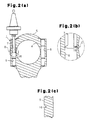
FIG. 2( a) is a cross-sectional view showing a notch forming mode in this embodiment;
FIG. 2( b) is an enlarged view showing a section B in FIG. 2( a);
FIG. 2( c) is an enlarged view showing a section C in FIG. 2( b);
FIG. 3 is a cross-sectional view showing another notch forming mode in this embodiment;
FIG. 4( a) is a cross-sectional plan view showing a split mold adopted in this embodiment;
FIG. 4( b) is a cross-sectional side view of the split mold;
FIG. 5( a) is a cross-sectional view showing a mode of inserting the split mold into a bolt hole in this embodiment;
FIG. 5( b) is an enlarged view of a section D in FIG. 5( a);
FIG. 6 is a cross-sectional view showing a connecting rod breaking mode in this embodiment;
FIG. 7 is a cross-sectional view showing a breakage progress propagating mode in this embodiment;
FIG. 8 is a view showing a buckling occurring mode in breaking of the connecting rod;
FIG. 9 is a cross-sectional view showing a connecting rod breaking mode in a second embodiment of the present invention;
FIG. 10 is a cross-sectional view showing a connecting rod breaking mode in a modification of the first embodiment, in which structures of the split mold and a wedge are changed;
FIG. 11( a) is a cross-sectional view showing a conventional connecting rod breaking mode;
FIG. 11( b) is an enlarged view of a section E in FIG. 11( a);
FIG. 12 is a cross-sectional view showing a breakage progress propagating mode in a conventional connecting rod breaking method; and
FIG. 13 is a cross-sectional side view showing a large end of a connecting rod having a breaking surface step.
DETAILED DESCRIPTION OF THE PREFERRED EMBODIMENTS First Embodiment
A connecting rod breaking method according a first embodiment of the present invention will be described in detail with reference to FIGS. 1 to 8. As shown in FIG. 1, a connecting rod 1 to be broken is integrally molded by forging so as to have one end as a small end 3, in which a small end hole 2 pivotally supporting a piston pin is formed, and the other end as a large end 5, in which a large end hole 4 pivotally supporting a journal portion of a crank shaft is formed. A bolt hole 6, into which a bolt for fastening the cap portion and the rod portion of the connecting rod 1, which are divided by breaking, is formed at each side of the large end 5.
The connecting rod 1 is manufactured by breaking an integral mold formed by forging into the cap portion and the rod portion in the large end 5. In this embodiment, the connecting rod 1 is broken through the following steps 1 to 3.
Step 1: forming a notch that extends continuously along the inner circumference of the bolt hole 6 on each side of the large end 5.
Step 2: inserting a split mold into each bolt hole 6.
Step 3: applying a load to each split mold to press the notch in a radial direction, thereby breaking the connecting rod 1 into the rod portion and the cap portion.
Forming of the notch in Step 1 can be performed, for example, in a mode shown in FIG. 2( a). That is, a single point tap 7 is inserted into the bolt hole 6 and is rotated so that its edge goes around the inner circumference of the bolt hole 6, thereby forming the notch 16 that extends continuously along the inner circumference of the bolt hole 6. FIG. 2( b) is an enlarged view of a section B in FIG. 2( a), and FIG. 2( c) is an enlarged view of a section C in FIG. 2( b).
The notch 16 may also be formed by laser processing. In this case, the notch 16 is formed in a mode shown in FIG. 3. That is, a mirror 9 attached to a distal end of a rotational shaft 8 is inserted into the bolt hole 6, and an optical path of laser light from a laser head 10 is bent toward the bolt hole 6 so that the inner circumference of the bolt hole 6 is irradiated with the laser light. Then, by rotating the mirror 9 together with the rotational shaft 8 and applying the laser light so as to go around the inner circumference of the bolt hole 6, the notch 16 that extends continuously along the inner circumference of the bolt hole 6 is formed.
In the following Step 2, the split mold 11 as shown in FIG. 4 is inserted into the bolt hole 6. As shown in FIGS. 4( a) and 4(b), the split mold 11 is annular and has wedge-like projections 12 inserted into the notch 16 in its outer circumference. This split mold 11 is divided into two parts 11 a, 11 b.
The split mold 11 is installed in the bolt hole 6 as shown in FIGS. 5( a) and 5(b). That is, the split mold 11 is inserted into the bolt hole 6 while being placed on a support column 13 inserted from an opening of the bolt hole 6, which is shown in a lower section in this drawing. In the following Step 3, a longitudinal pulling force as pre-tension is applied to the connecting rod 1.
In the following Step 3, as shown in FIG. 6, a substantially columnar wedge 14 having a wedge-like distal end is inserted from an opening on the opposite side to the opening into which the support column 13 is inserted in a state where both sides of the large end 5 are supported by cap guides 15. Then, by pressing a bottom end of the wedge 14 by a wedge movable pressing portion 17 downward in this drawing, the distal end of the wedge 14 is driven between the two parts 11 a, 11 b of the split mold 11 to increase the interval between the parts 11 a, 11 b of the split mold 11, thereby breaking the connecting rod 1 in the large end 5.
When it is attempted to reliably drive the wedge 14 straight, a guide may be arranged about the outer circumference of the wedge 14, and the wedge 14 may be driven with its outer circumference held by the guide.
As shown in FIG. 7, progress of breakage at this time radially propagates from the inner circumference of the bolt hole 6 using the notch 16 in the inner circumference as the starting point. Thus, in breaking at this time, no confluence of breakage propagation exists.
The above-mentioned embodiment achieves following advantages.
(1) In this embodiment, the notch 16 is formed in the inner circumference of the bolt hole 6, which is provided on each side of the large end 5 and into which a bolt for fastening the rod portion and the cap portion is inserted, such that the notch 16 extends continuously along the inner circumference of the bolt hole 6, and progress of breakage propagates using the notch 16 as the starting point to break the connecting rod 1. According to such a breaking method in this embodiment, since progress of breakage radially proceeds from the inner circumference of the bolt hole 6 using the notch 16 formed in the inner circumference as the starting point, no confluence of breakage propagation exists. Therefore, according to the breaking method in this embodiment, the connecting rod 1 can be broken without generating any breaking surface step.
(2) In this embodiment, the connecting rod 1 is broken by the step of forming the notch 16, the step of inserting the split mold 11 into the bolt hole 6, and the step of applying a load to the split mold 11 to press the notch 16 in the radial direction, thereby breaking the connecting rod 1 into the rod portion and the cap portion. In breaking of the connecting rod 1, the annular split mold 11 that has the wedge-like projection 12 inserted into the notch 16 in its outer circumference and is divided into two parts 11 a, 11 b is used. Then, by driving the wedge 14 between the two parts 11 a, 11 b, which constitute the split mold 11, to increase the interval between the parts 11 a,11 b, the connecting rod 1 is broken. Therefore, using the notch 16 formed in the inner circumference of the bolt hole 6 as the starting point, progress of breakage can proceed radially from the inner circumference more reliably.
(3) Breaking of the connecting rod 1 is independently performed on both sides of the large end 5. When there is a time difference between breaking on both sides, as shown in FIG. 8, a first broken region may be opened, causing buckling. In this connection, in this embodiment, since the connecting rod is broken in the state where both sides of the large end 5 are held by the cap guides 15, such buckling is prevented.
Second Embodiment
A connecting rod breaking method according to a second embodiment of the present invention will be described in detail with reference to FIG. 9. In this embodiment, the same configurations as those in the first embodiment are given the same reference numerals and detailed description thereof is omitted.
In this embodiment, as in the first embodiment, a notch 16 that extends continuously along the inner circumference of a bolt hole 6 is formed in the inner circumference. In this embodiment, a connecting rod 1 is broken according to a mode shown in FIG. 9.
That is, in this embodiment, in breaking of the connecting rod 1, a split mold 20 constituted of two semicircular parts 20 a, 20 b is inserted into the large end hole 4. Then, by pressing the large end 5 of the connecting rod 1 by a guide 21 and driving a wedge 22 between the two parts 20 a, 20 b of the split mold 20 while applying a pulling force in the longitudinal direction as pre-tension to increase an interval between the two parts 20 a, 20 b, the connecting rod 1 is broken.
Also in this case, progress of breakage radially propagates outward from the inner circumference of the bolt hole 6 using the notch 16 in the inner circumference as the starting point. For this reason, also in this embodiment, no confluence of breakage propagation exists and therefore, no breaking surface step is generated.
Each of the above-mentioned embodiments can be modified and implemented as follows.
In the first embodiment, the connecting rod 1 is broken in the state where the sides of the large end 5 are held by the cap guides 15. However, as long as breaking can be achieved without generating a time difference between the sides of the large end 5, the cap guides 15 may be omitted.
In the first embodiment, the connecting rod 1 is broken by using the two-way split mold 11, which is annular and has the wedge-like projection 12 inserted into the notch 16 in its outer circumference. However, as long as progress of breakage radially propagates using the notch 16 as the starting point, the shape and configuration of the split mold 11 may be appropriately changed. For example, by using a split mold 30 and a wedge 31 as shown in FIG. 10, the connecting rod 1 can be broken without generating any breaking surface step.
Although the connecting rod 1 is broken by driving the wedge in the above-mentioned embodiments, the connecting rod 1 may be broken according to other methods such as by applying a shock load in a pulling direction in a longitudinal direction of the connecting rod 1. Also in this case, when the notch 16 is formed in the inner circumference of the bolt hole 6 so as to extend continuously along the inner circumference and progress of breakage radially propagates using the notch 16 as the starting point to break the connecting rod 1, the confluence of breakage propagation is eliminated, thereby preventing occurrence of the breaking surface step.
DESCRIPTION OF THE REFERENCE NUMERALS
1 . . . Connecting Rod, 2 . . . Small End Hole, 3 . . . Small End, 4 . . . Large End Hole, 5 . . . Large End, 6 . . . Bolt Hole, 7 . . . Single Point Tap, 8 . . . Rotational Shaft, 9 . . . Mirror, 10 . . . Laser Head, 11 . . . Split Mold (11 a, 11 b: Two parts Constituting A Split Mold), 12 . . . Projection, 13 . . . Support Column, 14 . . . Wedge, 15 . . . Cap Guide, 16 . . . Notch, 17 . . . Wedge Movable Pressing Portion, 20 . . . Split Mold (20 a, 20 b: Two parts Constituting A Split Mold), 21 . . . Guide, 22 . . . Wedge, 30 . . . Split Mold, 31 . . . Wedge, 50 . . . Split Mold, 51 . . . Split Mold, 52 . . . Connecting Rod, 53 . . . Large End Hole, 54 . . . Wedge, 55 . . . Notch, 56 . . . Large End, 57 . . . Bolt Hole.

Claims (7)

The invention claimed is:
1. A method for breaking an integrally molded connecting rod into a rod portion and a cap portion in a large end in which a large end hole is formed,
the method comprising:
forming a notch in an inner circumference of a bolt hole, which is formed on each side of the large end and into which a bolt for fastening the rod portion and the cap portion to each other is inserted, such that the notch extends continuously along all around the inner circumference; and
performing the breaking by radially propagating progress of breakage from the notch as a starting point, so that no confluence of breakage propagation exists.
2. The connecting rod breaking method according to claim 1, comprising:
inserting a split mold into each bolt hole; and
applying a load to the split mold to press the notch in a radial direction, thereby breaking the connecting rod into the rod portion and the cap portion.
3. The connecting rod breaking method according to claim 2, wherein the split mold is annular and has in its outer circumference a wedge-like projection inserted into the notch.
4. The connecting rod breaking method according to claim 3, wherein the split mold is divided into two, the method further comprises driving a wedge between the two parts constituting the split mold to increase an interval between the parts, thereby breaking the connecting rod.
5. The connecting rod breaking method according to claim 1, wherein the connecting rod is broken in a state where the sides of the large end are held by cap guides.
6. The connecting rod breaking method according to claim 1, further comprising:
inserting a spilt mold into the large end hole;
pressing the large end with a guide and driving a wedge in the spilt mold while applying a pulling force in the longitudinal direction.
7. The connecting rod breaking method according to claim 6, wherein the split mold includes two semicircular parts that are inserted into the large end hole.
US13/513,866 2011-01-24 2011-01-24 Connecting rod breaking method Active 2031-06-21 US8875966B2 (en)

Applications Claiming Priority (1)

Application Number Priority Date Filing Date Title
PCT/JP2011/051247 WO2012101748A1 (en) 2011-01-24 2011-01-24 Method for breaking off connecting rod

Publications (2)

Publication Number Publication Date
US20120267413A1 US20120267413A1 (en) 2012-10-25
US8875966B2 true US8875966B2 (en) 2014-11-04

Family

ID=46580358

Family Applications (1)

Application Number Title Priority Date Filing Date
US13/513,866 Active 2031-06-21 US8875966B2 (en) 2011-01-24 2011-01-24 Connecting rod breaking method

Country Status (5)

Country Link
US (1) US8875966B2 (en)
EP (1) EP2669536B1 (en)
JP (1) JP5267739B2 (en)
CN (1) CN102725100B (en)
WO (1) WO2012101748A1 (en)

Families Citing this family (2)

* Cited by examiner, † Cited by third party
Publication number Priority date Publication date Assignee Title
JP6091021B2 (en) * 2015-03-12 2017-03-08 本田技研工業株式会社 Breaking and splitting device
US11117191B2 (en) * 2018-10-30 2021-09-14 GM Global Technology Operations LLC Methods for manufacturing connecting rod assemblies and crankshaft assemblies

Citations (20)

* Cited by examiner, † Cited by third party
Publication number Priority date Publication date Assignee Title
US2703263A (en) * 1952-11-14 1955-03-01 Mercury Engineering Corp Connecting rod
US3818577A (en) * 1971-01-15 1974-06-25 Caterpillar Tractor Co Connecting rod manufacturing
US3994054A (en) * 1975-01-06 1976-11-30 Brunswick Corporation Multiple part tubular member and method and apparatus for manufacture thereof
US4684267A (en) * 1984-07-02 1987-08-04 General Motors Corporation Split bearing assemblies
JPH01272705A (en) 1988-02-27 1989-10-31 Sintermetallwerk Krebsoege Gmbh Method for production of powder forged parts
US20020023939A1 (en) * 2000-08-24 2002-02-28 Yasunaga Corporation Connecting rod fracture machine and method for fracture separating connecting rod using the machine
US6474526B1 (en) * 1997-08-01 2002-11-05 Alfing Kessler Sondermaschinen Gmbh Method for fracture-separating an annular piece
US6641016B2 (en) * 1999-04-21 2003-11-04 Alfing Kessler Sondermaschinen Gmbh Device for fracture-splitting a workpiece
JP2004245237A (en) 2003-02-10 2004-09-02 Honda Motor Co Ltd Cutting/splitting processing method for connecting rod
JP2005014094A (en) 2003-06-23 2005-01-20 Yasunaga Corp Rupturing device of connecting rod and method of manufacturing ruptured connecting rod
US20050011924A1 (en) * 2003-07-15 2005-01-20 Yasuo Momose Machining apparatus for forming cracking slot for connecting rod
JP2005106271A (en) 2002-12-26 2005-04-21 Yamaha Motor Co Ltd Split type connecting rod
JP2006150472A (en) 2004-11-25 2006-06-15 Honda Motor Co Ltd Processing device of cracking groove for connecting rod
US20060260433A1 (en) 2005-05-20 2006-11-23 Yamaha Hatsudoki Kabushiki Kaisha Connecting rod and internal combustion engine and automotive vehicle incorporating the same
JP2006322599A (en) 2005-05-20 2006-11-30 Yamaha Motor Co Ltd Con'rod and internal combustion engine and motor vehicle comprising the same
US7143915B2 (en) * 1999-10-13 2006-12-05 Sameh Guirgis Process to fracture connecting rods and the like with resonance-fatigue
JP2007529694A (en) 2004-03-19 2007-10-25 アルフィング ケスラー サンデルマスチネン ゲーエムベーハー Method and apparatus for manufacturing split bearing components
US20080061100A1 (en) * 2004-06-11 2008-03-13 Alfing Kessler Sondermaschinen Gmbh Device And Method For Fracture Splitting Of Workpieces
CN101352795A (en) 2007-07-27 2009-01-28 云南西仪工业股份有限公司 Method for processing fractured connecting rod for car engine
JP2010071438A (en) 2008-09-22 2010-04-02 Mazda Motor Corp Metallic product and method for manufacturing the same

Family Cites Families (1)

* Cited by examiner, † Cited by third party
Publication number Priority date Publication date Assignee Title
DE10021172A1 (en) * 2000-04-29 2001-06-21 Daimler Chrysler Ag Connecting rod has mounting eye made of upper and lower parts fastened together by bolts in threaded bores, contoured section in wall of bore initiating separation of parts

Patent Citations (21)

* Cited by examiner, † Cited by third party
Publication number Priority date Publication date Assignee Title
US2703263A (en) * 1952-11-14 1955-03-01 Mercury Engineering Corp Connecting rod
US3818577A (en) * 1971-01-15 1974-06-25 Caterpillar Tractor Co Connecting rod manufacturing
US3994054A (en) * 1975-01-06 1976-11-30 Brunswick Corporation Multiple part tubular member and method and apparatus for manufacture thereof
US4684267A (en) * 1984-07-02 1987-08-04 General Motors Corporation Split bearing assemblies
JPH01272705A (en) 1988-02-27 1989-10-31 Sintermetallwerk Krebsoege Gmbh Method for production of powder forged parts
US4923674A (en) 1988-02-27 1990-05-08 Sintermetallwerk Krebsoge Gmbh Method of producing powder forged components
US6474526B1 (en) * 1997-08-01 2002-11-05 Alfing Kessler Sondermaschinen Gmbh Method for fracture-separating an annular piece
US6641016B2 (en) * 1999-04-21 2003-11-04 Alfing Kessler Sondermaschinen Gmbh Device for fracture-splitting a workpiece
US7143915B2 (en) * 1999-10-13 2006-12-05 Sameh Guirgis Process to fracture connecting rods and the like with resonance-fatigue
US20020023939A1 (en) * 2000-08-24 2002-02-28 Yasunaga Corporation Connecting rod fracture machine and method for fracture separating connecting rod using the machine
JP2005106271A (en) 2002-12-26 2005-04-21 Yamaha Motor Co Ltd Split type connecting rod
JP2004245237A (en) 2003-02-10 2004-09-02 Honda Motor Co Ltd Cutting/splitting processing method for connecting rod
JP2005014094A (en) 2003-06-23 2005-01-20 Yasunaga Corp Rupturing device of connecting rod and method of manufacturing ruptured connecting rod
US20050011924A1 (en) * 2003-07-15 2005-01-20 Yasuo Momose Machining apparatus for forming cracking slot for connecting rod
JP2007529694A (en) 2004-03-19 2007-10-25 アルフィング ケスラー サンデルマスチネン ゲーエムベーハー Method and apparatus for manufacturing split bearing components
US20080061100A1 (en) * 2004-06-11 2008-03-13 Alfing Kessler Sondermaschinen Gmbh Device And Method For Fracture Splitting Of Workpieces
JP2006150472A (en) 2004-11-25 2006-06-15 Honda Motor Co Ltd Processing device of cracking groove for connecting rod
US20060260433A1 (en) 2005-05-20 2006-11-23 Yamaha Hatsudoki Kabushiki Kaisha Connecting rod and internal combustion engine and automotive vehicle incorporating the same
JP2006322599A (en) 2005-05-20 2006-11-30 Yamaha Motor Co Ltd Con'rod and internal combustion engine and motor vehicle comprising the same
CN101352795A (en) 2007-07-27 2009-01-28 云南西仪工业股份有限公司 Method for processing fractured connecting rod for car engine
JP2010071438A (en) 2008-09-22 2010-04-02 Mazda Motor Corp Metallic product and method for manufacturing the same

Non-Patent Citations (1)

* Cited by examiner, † Cited by third party
Title
International Search Report Issued Feb. 15, 2011 in PCT/JP11/51247 Filed Jan. 24, 2011.

Also Published As

Publication number Publication date
JP5267739B2 (en) 2013-08-21
US20120267413A1 (en) 2012-10-25
WO2012101748A1 (en) 2012-08-02
CN102725100B (en) 2015-08-12
EP2669536A1 (en) 2013-12-04
EP2669536A4 (en) 2018-01-24
JPWO2012101748A1 (en) 2014-06-30
CN102725100A (en) 2012-10-10
EP2669536B1 (en) 2019-05-22

Similar Documents

Publication Publication Date Title
US8875966B2 (en) Connecting rod breaking method
KR20140066790A (en) Radial foil bearing
US10845004B2 (en) High-pressure container and shell reinforcing layer wrapping method
US10514059B2 (en) Bearing device
US10732572B2 (en) Horological rivet
JP5703991B2 (en) Connecting rod fracture splitting method and apparatus
JP2015169304A (en) Resin member having flanged fastening member
US9364774B2 (en) Chain structure
US20180180160A1 (en) Friction pulley
EP1398103A1 (en) Device and method for machining connecting rods and connecting rods so produced
JP2005096066A (en) Device and method for rupturing and splitting connecting rod
US9115745B2 (en) Securing nut
JP2015021610A (en) Manufacturing method of connecting rod, and connecting rod manufactured by the manufacturing method
JP5921713B2 (en) Drive belt for a continuously variable transmission having a transverse member with a contact area
JP5393533B2 (en) Cylinder block
JP5210607B2 (en) V belt for high load transmission
JP5760692B2 (en) Permanent magnet base material cleaving device, permanent magnet base material cleaving method
US9770752B2 (en) Manufacturing method of gears for a speed change device and its apparatus
JP5947223B2 (en) Tensioner
JP2006125595A (en) Connecting rod
JP2017211041A (en) Press-fit structure
JP2010121746A (en) Synchronizer ring
JP4890480B2 (en) Manufacturing method of tensioner lever
JP2009184064A (en) Fracture method of metal member and fracture device of metal member
WO2010116418A1 (en) V-belt for transmitting high load

Legal Events

Date Code Title Description
AS Assignment

Owner name: TOYOTA JIDOSHA KABUSHIKI KAISHA, JAPAN

Free format text: ASSIGNMENT OF ASSIGNORS INTEREST;ASSIGNORS:ABE, MAMI;YOKOTA, JUNJI;OKUGAWA, MICHITAKA;SIGNING DATES FROM 20120411 TO 20120420;REEL/FRAME:028336/0613

STCF Information on status: patent grant

Free format text: PATENTED CASE

MAFP Maintenance fee payment

Free format text: PAYMENT OF MAINTENANCE FEE, 4TH YEAR, LARGE ENTITY (ORIGINAL EVENT CODE: M1551)

Year of fee payment: 4

MAFP Maintenance fee payment

Free format text: PAYMENT OF MAINTENANCE FEE, 8TH YEAR, LARGE ENTITY (ORIGINAL EVENT CODE: M1552); ENTITY STATUS OF PATENT OWNER: LARGE ENTITY

Year of fee payment: 8