US8873162B2 - Optical system - Google Patents
Optical system Download PDFInfo
- Publication number
- US8873162B2 US8873162B2 US12/586,284 US58628409A US8873162B2 US 8873162 B2 US8873162 B2 US 8873162B2 US 58628409 A US58628409 A US 58628409A US 8873162 B2 US8873162 B2 US 8873162B2
- Authority
- US
- United States
- Prior art keywords
- lens
- unit
- optical system
- lens unit
- group
- Prior art date
- Legal status (The legal status is an assumption and is not a legal conclusion. Google has not performed a legal analysis and makes no representation as to the accuracy of the status listed.)
- Active, expires
Links
- 230000003287 optical effect Effects 0.000 title claims abstract description 138
- 238000003384 imaging method Methods 0.000 claims abstract description 13
- 239000006185 dispersion Substances 0.000 claims description 18
- 239000000463 material Substances 0.000 claims description 13
- 239000011521 glass Substances 0.000 claims description 12
- 210000001747 pupil Anatomy 0.000 claims description 6
- 230000000295 complement effect Effects 0.000 claims description 3
- 229910044991 metal oxide Inorganic materials 0.000 claims description 3
- 150000004706 metal oxides Chemical class 0.000 claims description 3
- 239000004065 semiconductor Substances 0.000 claims description 3
- 230000008859 change Effects 0.000 abstract description 6
- 238000001228 spectrum Methods 0.000 description 10
- 230000004075 alteration Effects 0.000 description 6
- 238000010276 construction Methods 0.000 description 5
- 210000001525 retina Anatomy 0.000 description 5
- 210000000887 face Anatomy 0.000 description 3
- 238000010586 diagram Methods 0.000 description 2
- 230000002349 favourable effect Effects 0.000 description 2
- 230000009467 reduction Effects 0.000 description 2
- 101100190324 Pyrenochaetopsis sp phm2 gene Proteins 0.000 description 1
- 101100210189 Saccharomyces cerevisiae (strain ATCC 204508 / S288c) VTC3 gene Proteins 0.000 description 1
- 230000003247 decreasing effect Effects 0.000 description 1
- 238000006073 displacement reaction Methods 0.000 description 1
- 230000000694 effects Effects 0.000 description 1
- 239000005304 optical glass Substances 0.000 description 1
- 230000037361 pathway Effects 0.000 description 1
- 239000005342 prism glass Substances 0.000 description 1
- 230000007704 transition Effects 0.000 description 1
- 238000011144 upstream manufacturing Methods 0.000 description 1
Images


Classifications
-
- G—PHYSICS
- G02—OPTICS
- G02B—OPTICAL ELEMENTS, SYSTEMS OR APPARATUS
- G02B15/00—Optical objectives with means for varying the magnification
- G02B15/14—Optical objectives with means for varying the magnification by axial movement of one or more lenses or groups of lenses relative to the image plane for continuously varying the equivalent focal length of the objective
- G02B15/16—Optical objectives with means for varying the magnification by axial movement of one or more lenses or groups of lenses relative to the image plane for continuously varying the equivalent focal length of the objective with interdependent non-linearly related movements between one lens or lens group, and another lens or lens group
- G02B15/163—Optical objectives with means for varying the magnification by axial movement of one or more lenses or groups of lenses relative to the image plane for continuously varying the equivalent focal length of the objective with interdependent non-linearly related movements between one lens or lens group, and another lens or lens group having a first movable lens or lens group and a second movable lens or lens group, both in front of a fixed lens or lens group
- G02B15/167—Optical objectives with means for varying the magnification by axial movement of one or more lenses or groups of lenses relative to the image plane for continuously varying the equivalent focal length of the objective with interdependent non-linearly related movements between one lens or lens group, and another lens or lens group having a first movable lens or lens group and a second movable lens or lens group, both in front of a fixed lens or lens group having an additional fixed front lens or group of lenses
- G02B15/173—Optical objectives with means for varying the magnification by axial movement of one or more lenses or groups of lenses relative to the image plane for continuously varying the equivalent focal length of the objective with interdependent non-linearly related movements between one lens or lens group, and another lens or lens group having a first movable lens or lens group and a second movable lens or lens group, both in front of a fixed lens or lens group having an additional fixed front lens or group of lenses arranged +-+
-
- G—PHYSICS
- G02—OPTICS
- G02B—OPTICAL ELEMENTS, SYSTEMS OR APPARATUS
- G02B15/00—Optical objectives with means for varying the magnification
- G02B15/14—Optical objectives with means for varying the magnification by axial movement of one or more lenses or groups of lenses relative to the image plane for continuously varying the equivalent focal length of the objective
- G02B15/143—Optical objectives with means for varying the magnification by axial movement of one or more lenses or groups of lenses relative to the image plane for continuously varying the equivalent focal length of the objective having three groups only
- G02B15/1431—Optical objectives with means for varying the magnification by axial movement of one or more lenses or groups of lenses relative to the image plane for continuously varying the equivalent focal length of the objective having three groups only the first group being positive
- G02B15/143105—Optical objectives with means for varying the magnification by axial movement of one or more lenses or groups of lenses relative to the image plane for continuously varying the equivalent focal length of the objective having three groups only the first group being positive arranged +-+
-
- G—PHYSICS
- G02—OPTICS
- G02B—OPTICAL ELEMENTS, SYSTEMS OR APPARATUS
- G02B23/00—Telescopes, e.g. binoculars; Periscopes; Instruments for viewing the inside of hollow bodies; Viewfinders; Optical aiming or sighting devices
Definitions
- This application relates to an optical system for imaging an object on an image acquisition unit, in particular, an optical system having a variable focal length for zooming.
- a telescope having a variable magnification is known from DE 704 17 03, which is incorporated herein by reference.
- the telescope has an optical system in the form of a zoom objective, a prism reversal system, and an ocular.
- the zoom objective is provided with four lens units, namely a first lens unit, a second lens unit, a third lens unit, and a fourth lens unit.
- the zoom objective is a four-number system.
- Two of the above-mentioned lens units, namely the second lens unit and the third lens unit, are situated so they are movable along the optical axis.
- the first lens unit and the fourth lens unit are situated fixed on the optical axis.
- the fourth lens unit is used for implementing the main portion of the required refractive power of the objective.
- the fourth lens unit is a main objective, essentially having an afocal adapter having variable magnification connected upstream.
- the afocal adapter includes the fixed first lens unit, the movable second lens unit, and the movable third lens unit.
- the above-mentioned construction including a main objective having an afocal adapter, has the disadvantage that a large overall objective length results in comparison to the maximum achievable focal length of the zoom objective. This is undesirable.
- a telescope having an objective of variable focal length (zoom objective), a prism reversal system, and having an ocular having a fixed focal length is known from U.S. Pat. No. 3,069,972, which is incorporated herein by reference.
- the objective of the known telescope is constructed according to the principle of optical compensation. For this reason, only a movement along the optical axis is necessary, which is executed by a first lens unit and a second lens unit, between which a fixed third lens unit is situated.
- the known telescope however, has the disadvantage because of the principle of optical compensation that the location of the image plane of the object to be imaged fluctuates over the magnification range of the telescope.
- a zoom telescope is known from DE 10 2004 001 481 A1, which is incorporated herein by reference, which includes an optical system in the form of an objective of variable focal length, an ocular of fixed focal length, and a prism reversal system, the prism reversal system being situated between the objective and the ocular.
- the objective has a first lens unit, a second lens unit, and a third lens unit from an object in the direction of the ocular.
- the second lens unit and the third lens unit are situated so they are movable along the optical axis of the objective for zooming.
- the first lens unit of the objective includes a first lens group, which has a cemented element, and a second lens group, which only includes a single lens.
- focusing must be performed by moving lens units along the optical axis of the objective, these movable lens units being in front of the movable second lens unit and the movable third lens unit, which are used for changing the focal length. It is known from DE 10 2004 001 481 A1 that the setting to finite object distance is performed by displacing the entire first lens unit along the optical axis of the objective or, alternatively thereto, only by a movement of the second lens group of the first lens unit, the second lens group including a single lens.
- a constant field of vision is achieved by using a zoom objective and by situating a field aperture in the intermediate image after the zoom objective and/or the prism reversal system.
- An intermediate image having equal diameter results for all zoom settings of the zoom objective in this way.
- a constant subjective field of vision results after the ocular, independently of the zoom setting.
- the known telescope has the disadvantage that a displacement of the entire first lens unit to set finite object distances requires an overall length change of the objective (and thus also of the entire telescope). This can be avoided using internal focusing by sole movement of the second lens group of the first lens unit.
- the spherical aberration and the chromatic errors of the objective change very strongly. This is disadvantageous in particular for objectives having a large maximum focal length (for example, 500 mm).
- An objective of an above-mentioned telescope from the prior art is typically achromatically corrected.
- the vertex image distances for red and blue light are thus equally long, but the vertex image distances for green light deviate.
- This deviation is typically referred to as a longitudinal chromatic aberration or also as a secondary spectrum.
- the secondary spectrum of the objective of a telescope of this type often results in color fringes at light-dark transitions. These are often very annoying to an observer who observes an object using the telescope. This interference is all the more obvious the greater the focal length of the objective and thus a magnification of the object is selected on the telescope.
- an optical system for imaging an object on an image acquisition unit.
- the image acquisition unit may be understood to include a wide range of suitable units for image acquisition in accordance with the system described herein.
- the optical system may be implemented as an objective for a telescope.
- the magnification range of the telescope may be from 15 ⁇ to 45 ⁇ or from 20 ⁇ to 60 ⁇ , for example.
- the image acquisition unit may be the retina of an observer, for example.
- embodiments of the system described herein may also be provided in which the optical system according to the system described herein is implemented for imaging an object on an image acquisition unit in the form of a surface sensor, such as a charge-coupled device (CCD) and/or a complementary metal oxide semiconductor (CMOS) sensor, among other suitable image acquisition unit designs.
- a surface sensor such as a charge-coupled device (CCD) and/or a complementary metal oxide semiconductor (CMOS) sensor, among other suitable image acquisition unit designs.
- CCD charge-coupled device
- CMOS complementary metal oxide semiconductor
- the optical system according to an embodiment of the system described herein may have precisely three lens units from the object in the direction of an image acquisition unit, namely a first lens unit, a second lens unit, and a third lens unit.
- a lens unit may be understood herein as a single lens or also as a lens unit assembled from multiple lenses.
- the second lens unit and the third lens unit may be situated so they are movable along an optical axis of the optical system for a change of the focal length (zooming).
- the first lens unit may include a first lens group and a second lens group.
- a lens group may be understood as a single lens or also as a lens group assembled from multiple lenses. Further lens groups may not be provided in the first lens unit.
- the first lens group of the first lens unit may be situated so it is stationary on the optical axis of the optical system. It may, accordingly, be fixed.
- the second lens group of the first lens unit may be situated so it is movable along the optical axis of the optical system for focusing, however.
- the second lens group may include at least two lenses.
- the optical system may have a fixed overall length.
- the first lens unit may have a telephoto effect, which results in a shortened overall length of the optical system relative to the maximum focal length of the optical system.
- only lenses of the first lens unit may be implemented having the free diameter as large as the entry pupil diameter of the optical system. All other lenses may have a free diameter which is significantly smaller.
- the maximum focal length of the optical system may be implemented substantially solely by the first lens unit.
- the second lens unit and the third lens unit may form a zoom system downstream from the first lens unit for reducing the focal length.
- a reduction of the secondary spectrum is made possible, in particular at the maximum focal length of the optical system.
- This construction may also have a favorable effect on the overall length of the optical system.
- considerations have shown that the relative aperture of the optical system at a maximum focal length may be at least 1:5.9.
- the first lens unit may be implemented as a converging first lens unit.
- the second lens unit may in turn be implemented as a dispersive second lens unit.
- the third lens unit may be implemented as a converging third lens unit.
- the first lens group of the first lens unit may be implemented as a converging first lens group, while, in contrast, the second lens group of the first lens unit may be implemented as a dispersive second lens group.
- the first lens group may have a first lens implemented as a converging lens, a second lens implemented as a converging lens, and a third lens implemented as a dispersive lens.
- the second lens group in turn may have a fourth lens implemented as a converging lens and a fifth lens implemented as a dispersive lens.
- the second lens group may be implemented as a cemented element.
- the second lens unit may also be assembled from multiple lenses. It is thus provided that the second lens unit may have a sixth lens implemented as a dispersive lens, a seventh lens implemented as a dispersive lens, and an eighth lens implemented as a converging lens. In addition, it may be provided that the seventh lens and the eighth lens form a dispersive cemented element.
- the third lens unit may also have multiple lenses in a further embodiment.
- the third lens unit may have a ninth lens implemented as a converging lens, a tenth lens implemented as a dispersive lens, an eleventh lens implemented as a converging lens, a twelfth lens implemented as a converging lens, and a thirteenth lens implemented as a dispersive lens.
- the twelfth lens and the thirteenth lens may form a dispersive cemented element.
- the second lens may be manufactured from a material whose deviation of the relative partial dispersion fulfills the following condition: ⁇ gF >0.025 (condition 1).
- the third lens may be manufactured from a material whose deviation of the relative partial dispersion fulfills the following condition: ⁇ gF ⁇ 0.005 (condition 2).
- the fifth lens may also be manufactured from a material whose deviation of the relative partial dispersion fulfills the following condition: ⁇ gF ⁇ 0.005 (condition 3).
- the eleventh lens may also be manufactured from a material whose deviation of the relative partial dispersion fulfills the following condition: ⁇ gF >0.004 (condition 4).
- the twelfth lens may in turn be manufactured from a material whose deviation of the relative partial dispersion fulfills the following condition: ⁇ gF 0.004 (condition 5).
- the thirteenth lens may be manufactured from a material whose deviation of the relative partial dispersion fulfills the following condition: ⁇ gF ⁇ 0.005 (condition 6).
- ⁇ gF describes the deviation of the relative partial dispersion in regard to the g-line and the F-line from a normal line which is provided by two reference glasses.
- these may be the glasses NSL7 and PHM2 from the OHARA company.
- the deviation of the relative partial dispersion from this normal line may be determined from the following formula:
- n g the index of refraction for the g-line
- n F being the index of refraction for the F-line
- n C being the index of refraction for the C-line.
- ⁇ d is the Abbe number for the d-line. The corresponding dimensions may be taken from the catalogs of the manufacturers of optical glasses for lens units.
- the first lens unit, the second lens unit, and the third lens unit and the first lens, second lens, third lens, fourth lens, fifth lens, sixth lens, seventh lens, eighth lens, ninth lens, tenth lens, eleventh lens, twelfth lens, and thirteenth lens contained in the above-mentioned lens units may have the following properties:
- the individual faces of the lenses and their radii are specified in the above-mentioned Table 1. Furthermore, the distance of the vertex of a first face to the vertex of the proximal face is specified. This also indicates the thickness of the individual lenses. Furthermore, the index of refraction is identified by n e and the Abbe number is identified by ⁇ e in Table 1. In addition, the type of glass of the particular lenses is specified, the notation of the types of glass relating to types of glass of the OHARA company. The distances identified by D9, D14, and D23 GBE are variable distances which are selected as a function of the desired focal length. Examples of these distances at various focal lengths of the optical system are specified in Table 2.
- D23 GBE is the distance up to the paraxial image plane (Gaussian image plane GBE) without a prism glass pathway. Furthermore, the diameter of the entry pupil of the optical system, the relative aperture, and the angle aperture for the corresponding focal lengths are specified in Table 2.
- Table 3 specifies the individual focal lengths of the first lens unit, the second lens unit, and the third lens unit for the above-noted embodiment of the optical system according to the system described herein. Furthermore, the individual focal lengths of the first lens group and the second lens group of the first lens unit are specified.
- the radii and distances may be variable within ⁇ 10% and the indices of refraction n e and the Abbe numbers ⁇ e may be variable within ⁇ 5%.
- the system described herein also relates to a telescope which is implemented having an optical system which has at least one of the above-mentioned features or one of the above-mentioned feature combinations.
- the optical system may be implemented as an objective.
- the telescope may be implemented having at least one image acquisition unit.
- the system described herein may be used in a spotting scope, for example.
- the telescope may have an image acquisition unit in the form of a surface sensor, such as a CCD and/or a CMOS sensor.
- an image acquisition unit may be provided in the form of an ocular, using which an image of an object is imaged on the retina of an observer.
- both a surface sensor and also an ocular may be provided.
- a telescope according to this embodiment may allow for both observation of the object (retina) and also imaging of the object on a surface sensor simultaneously.
- a prism reversal system may be provided, which can be implemented as a deflection prism to shorten the overall length. Additionally or alternatively thereto, the prism reversal system may be implemented as a beam splitter, one portion of the beam being conducted to the ocular and another portion to the surface sensor.
- a telescope is known from the prior art which has an ocular having variable focal lengths.
- the ocular may have a fixed focal length in an embodiment of the telescope according to the system described herein.
- the field of vision may be constant over the entire magnification range. The large subjective field of vision may thus be already provided at a low magnification, which may be first achieved in a telescope having an ocular having variable focal length at a high or maximum magnification.
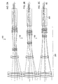
- FIGS. 1A-1C show a schematic illustration in the form of a lens section of a telescope having an optical system according to an embodiment of the system described herein;
- FIGS. 2A-2C show a schematic illustration of the embodiment according to FIG. 1 , only the optical system and a prism reversal system being shown;
- FIG. 3 shows a schematic illustration of the optical system according to FIGS. 1 and 2 in a setting for minimal focal length
- FIG. 4 shows a diagram in regard to the longitudinal chromatic error (secondary spectrum) for the optical system according to FIGS. 1C and 2C ;
- FIG. 5 shows a schematic illustration of a further optical system in the form of a telescope according to another embodiment of the system described herein.
- FIGS. 1A through 1C show a schematic illustration of a embodiment of a telescope 100 according to the system described herein.
- the telescope 100 may include an optical system in the form of an objective 200 , a prism reversal system 300 , and an ocular 400 .
- the prism reversal system 300 may additionally be implemented as a beam splitter for dividing incident beams into two partial beam paths.
- FIGS. 1A through 1C show various settings of the individual optical units of the telescope 100 , i.e., the objective 200 , in which various magnifications may be achieved. This is discussed in greater detail below.
- the objective 200 may have a variable focal length.
- the objective 200 may be designed for a focal length range from approximately 166.7 mm to approximately 500 mm.
- the telescope 100 will have a variable magnification from approximately 15 ⁇ to approximately 45 ⁇ .
- the magnification range of the telescope 100 is approximately 20 ⁇ to approximately 60 ⁇ .
- the field of vision of an observer may be constant over the entire above-mentioned magnification range and is 68°, for example.
- FIGS. 2A through 2C show a further schematic illustration of telescope 100 according to FIGS. 1A through 1C .
- a partial section of telescope 100 is shown, namely the area of the objective 200 and the prism reversal system 300 .
- the image plane of an object to be imaged is shown, which is identified by letter combination BE.
- Settings of the individual optical units of objective 200 are shown at a minimal focal length ( FIG. 2A ), at a moderate focal length ( FIG. 2B ), and at a maximal focal length ( FIG. 2C ).
- the setting of the focal length and focusing may be performed by movements of optical units of the objective 200 , which are explained in greater detail below on the basis of FIG. 3 .
- the objective 200 may have a first lens unit G 1 , a second lens unit G 2 , and a third lens unit G 3 from the object to be imaged in the direction of an image acquisition unit in the form of a retina of an observer (not shown) or in the direction of the ocular 400 .
- the first lens unit G 1 may be implemented as a converging first lens unit
- the second lens unit G 2 may be implemented as a dispersive second lens unit.
- the third lens unit G 3 may in turn be implemented as a converging third lens unit.
- the first lens unit G 1 may have a first lens group G 1 . 1 and a second lens group G 1 . 2 .
- the first lens group G 1 . 1 may include a first lens L 1 , implemented as a converging lens, a second lens L 2 , implemented as a converging lens, and a third lens L 3 , implemented as a dispersive lens, from the object in the direction of the image acquisition unit.
- the second lens group G 1 . 2 may have a fourth lens L 4 implemented as a converging lens and a fifth lens L 5 implemented as a dispersive lens.
- the fourth lens L 4 and the fifth lens L 5 may form a cemented element.
- the first lens group G 1 . 1 may be situated fixed on the optical axis of the objective 200 . It is therefore not moved.
- the second lens group G 1 . 2 may be situated as movable in regard to the optical axis of the objective 200 for focusing.
- the second lens unit G 2 may have a sixth lens L 6 implemented as a dispersive lens, a seventh lens L 7 implemented as a dispersive lens, and an eighth lens L 8 implemented as a converging lens.
- the seventh lens L 7 and the eighth lens L 8 may form a cemented element, which may be implemented as a dispersive element G 2 . 1 .
- the third lens unit G 3 may in turn have a ninth lens L 9 implemented as a converging lens, a tenth lens L 10 implemented as a dispersive lens, an eleventh lens L 11 implemented as a converging lens, and a dispersive element G 3 . 1 , which may be formed from a twelfth lens L 12 implemented as a converging lens and a thirteenth lens L 13 implemented as a dispersive lens.
- the dispersive element G 3 . 1 may be implemented as a cemented element.
- Both second lens unit G 2 and also third lens unit G 3 are implemented as movable on the optical axis of objective 200 for the focal length change (zooming).
- the individual faces of lenses L 1 through L 13 result from Table 4. Furthermore, the radii of the individual faces are specified. In addition, the distance of the vertex of a first face to the vertex of the next face is specified. This also indicates the thickness of individual lenses L 1 through L 13 . Face 26 is the position of the image plane. Because some lenses are situated so they are movable—as noted above—variable distances are specified in the table. These are the distances identified by D9, D14, and D23. The above-mentioned distances are selected depending on the desired focal length of objective 200 . Exemplary dimensions are specified in Table 5. Furthermore, the corresponding diameter of the entry pupil, the relative apertures, and the angle apertures at the corresponding focal lengths are specified.
- the first lens unit G 1 (including the first lens group G 1 . 1 and the second lens group G 1 . 2 ), the second lens unit G 2 , and the third lens unit G 3 have specific focal lengths, which are shown in Table 6.
- the maximum focal length of the objective 200 may already be approximately provided solely using the first lens unit G 1 .
- the second lens unit G 2 and the third lens unit G 3 may act as a zoom system downstream from the first lens unit G 1 for reducing the focal length.
- the above-mentioned construction may make the desired reduction of the secondary spectrum easier, in particular at the maximum focal length of the objective 200 . Furthermore, the above-mentioned construction may have a favorable effect on the overall objective length, which is not excessive.
- the lenses L 1 through L 13 may fulfill the above-mentioned conditions 1 through 6.
- the correction of the longitudinal chromatic error has not been brought precisely to apochromatic correction in the discussed embodiment, upon which the vertex distance may be equal for three wavelengths. Rather, an achromatic correction may be achieved, upon which the vertex distance may be equal for two wavelengths and the secondary spectrum may be greatly reduced.
- a good correction of the spherical aberration and the Gaussian error may be achieved, in particular at the maximum focal length of the objective 200 .
- the first lens L 1 may not be formed from glass which has a deviating relative partial dispersion. Glasses having a deviating relative partial dispersion are often more sensitive than other glasses, so that glasses having a deviating relative partial dispersion are not very well suited for protecting the other lenses. For this reason, the first lens L 1 may be formed from a somewhat less sensitive material.
- the paraxial longitudinal chromatic error s′ and longitudinal chromatic error s′m up to the best collection plane at the particular wavelength (nm) are shown.
- the difference between curves s′ and s′m may result from the spherical aberration and the Gaussian error.
- s′m influences the vertex distance according to which the image is focused. It is clear that the longitudinal chromatic error s′ is low.
- FIG. 5 shows a schematic illustration of a telescope 100 ′ according to another embodiment of the system described herein, which may also be provided with the objective 200 discussed above, the prism reversal system 300 discussed above, and the ocular 400 discussed above.
- the telescope 100 ′ may have an image acquisition unit in the form of a surface sensor 500 , such as a CCD and/or a CMOS sensor.
- the prism reversal system 300 may be implemented as a beam splitter, so that a portion of the incident beams are conducted to the ocular 400 and another portion of the incident light is conducted to the surface sensor 500 .
- This telescope 100 ′ may thus allow both an observation of the object (retina) and also imaging of the object on the surface sensor 500 simultaneously.
Landscapes
- Physics & Mathematics (AREA)
- General Physics & Mathematics (AREA)
- Optics & Photonics (AREA)
- Astronomy & Astrophysics (AREA)
- Lenses (AREA)
- Nonlinear Science (AREA)
Abstract
Description
ΔθgF>0.025 (condition 1).
ΔθgF<−0.005 (condition 2).
ΔθgF<−0.005 (condition 3).
ΔθgF>0.004 (condition 4).
ΔθgF0.004 (condition 5).
ΔθgF<−0.005 (condition 6).
ng being the index of refraction for the g-line, nF being the index of refraction for the F-line, and nC being the index of refraction for the C-line. νd is the Abbe number for the d-line. The corresponding dimensions may be taken from the catalogs of the manufacturers of optical glasses for lens units.
| TABLE 1 | ||||||
| Face | Radii | Distances [mm] | ne | νe | ΔθgF | Glass |
| First face | 193.452 | 8.800 | 1.489150 | 70.2 | 0.0022 | S-FSL5 |
| of the first | ||||||
| lens | ||||||
| Second | −461.963 | 0.300 | ||||
| face of the | ||||||
| first lens | ||||||
| First face | 133.330 | 13.800 | 1.498450 | 81.1 | 0.0280 | S-FPL51 |
| of the | ||||||
| second | ||||||
| lens | ||||||
| Second | −203.627 | 1.300 | ||||
| face of the | ||||||
| second | ||||||
| lens | ||||||
| First face | −199.963 | 4.300 | 1.616690 | 44.0 | −0.0065 | S-NBM51 |
| of the third | ||||||
| lens | ||||||
| Second | 199.963 | 89.054 | ||||
| face of the | ||||||
| third lens | ||||||
| First face | 172.546 | 8.400 | 1.624090 | 33.5 | 0.0070 | S-TIM2 |
| of the | ||||||
| fourth lens | ||||||
| First face | −60.561 | 2.400 | 1.616690 | 44.0 | −0.0065 | S-NBM51 |
| of the fifth | ||||||
| lens | ||||||
| Second | 76.744 | D9 | ||||
| face of the | ||||||
| fifth lens | ||||||
| First face | 8008.430 | 2.300 | 1.489150 | 70.2 | 0.0022 | S-FSL5 |
| of the | ||||||
| sixth lens | ||||||
| Second | 97.756 | 5.000 | ||||
| face of the | ||||||
| sixth lens | ||||||
| First face | −107.668 | 2.000 | 1.732340 | 54.4 | −0.0086 | S-LAL18 |
| of the | ||||||
| seventh | ||||||
| lens | ||||||
| First face | 68.366 | 5.000 | 1.812640 | 25.2 | 0.0158 | S-TIH6 |
| of the | ||||||
| eighth lens | ||||||
| Second | 346.508 | D14 | ||||
| face of the | ||||||
| eighth lens | ||||||
| First face | 116.707 | 5.000 | 1.591430 | 60.6 | −0.0018 | S-BAL35 |
| of the | ||||||
| ninth lens | ||||||
| Second | −150.657 | 6.000 | ||||
| face of the | ||||||
| ninth lens | ||||||
| First face | −45.364 | 3.500 | 1.761670 | 27.3 | 0.0133 | S-TIH4 |
| of the | ||||||
| tenth lens | ||||||
| Second | −59.427 | 0.500 | ||||
| face of the | ||||||
| tenth lens | ||||||
| First face | 65.995 | 5.000 | 1.620330 | 63.0 | 0.0051 | S-PHM52 |
| of the | ||||||
| eleventh | ||||||
| lens | ||||||
| Second | −202.293 | 0.500 | ||||
| face of the | ||||||
| eleventh | ||||||
| lens | ||||||
| First face | 54.889 | 5.500 | 1.620330 | 63.0 | 0.0051 | S-PHM52 |
| of the | ||||||
| twelfth | ||||||
| lens | ||||||
| First face | −223.543 | 2.000 | 1.616690 | 44.0 | −0.0065 | S-NBM51 |
| of the | ||||||
| thirteenth | ||||||
| lens | ||||||
| Second | 31.631 | D23GBE | ||||
| face of the | ||||||
| thirteenth | ||||||
| lens | ||||||
| TABLE 2 | |||||
| f′ [mm] | 167.3 | 334.6 | 501.9 | ||
| D9 [mm] | 35.773 | 76.325 | 119.468 | ||
| D14 [mm] | 101.408 | 42.598 | 13.255 | ||
| D23GBE [mm] | 110.217 | 128.476 | 114.676 | ||
| Entrance pupil | 38.44 | 65.3 | 85.0 | ||
| diameter [mm] | |||||
| Relative aperture | 1:4.4 | 1:5.1 | 1:5.9 | ||
| 2 * Sigma | 4.5° | 2.25° | 1.5° | ||
| TABLE 3 | |||
| Focal length first lens unit [mm] | 502.73 | ||
| Focal length first lens group [mm] | 251.95 | ||
| Focal length second lens group [mm] | −243.67 | ||
| Focal length second lens unit [mm] | −75.78 | ||
| Focal length third lens unit [mm] | 82.14 | ||
| TABLE 4 | ||||||
| Distances | ||||||
| Face | Radii | [mm] | ne | νe | ΔθgF | Glass |
| 1 | 193.452 | 8.800 | 1.489150 | 70.2 | 0.0022 | S- |
| 2 | −461.963 | 0.300 | ||||
| 3 | 133.330 | 13.800 | 1.498450 | 81.1 | 0.0280 | S- |
| 4 | −203.627 | 1.300 | ||||
| 5 | −199.963 | 4.300 | 1.616690 | 44.0 | −0.0065 | S- |
| 6 | 199.963 | 89.054 | ||||
| 7 | 172.546 | 8.400 | 1.624090 | 33.5 | 0.0070 | S- |
| 8 | −60.561 | 2.400 | 1.616690 | 44.0 | −0.0065 | S- |
| 9 | 76.744 | |
||||
| 10 | 8008.430 | 2.300 | 1.489150 | 70.2 | 0.0022 | S- |
| 11 | 97.756 | 5.000 | ||||
| 12 | −107.668 | 2.000 | 1.732340 | 54.4 | −0.0086 | S- |
| 13 | 68.366 | 5.000 | 1.812640 | 25.2 | 0.0158 | S- |
| 14 | 346.508 | |
||||
| 15 | 116.707 | 5.000 | 1.591430 | 60.6 | −0.0018 | S- |
| 16 | −150.657 | 6.000 | ||||
| 17 | −45.364 | 3.500 | 1.761670 | 27.3 | 0.0133 | S- |
| 18 | −59.427 | 0.500 | ||||
| 19 | 65.995 | 5.000 | 1.620330 | 63.0 | 0.0051 | S- |
| 20 | −202.293 | 0.500 | ||||
| 21 | 54.889 | 5.500 | 1.620330 | 63.0 | 0.0051 | S- |
| 22 | −223.543 | 2.000 | 1.616690 | 44.0 | −0.0065 | S- |
| 23 | 31.631 | |
||||
| 24 | Infinite | 107.254 | 1.571250 | 55.7 | N- |
|
| 25 | Infinite | 31.994 | ||||
| 26 | Infinite | |||||
| TABLE 5 | |||||
| f′ [mm] | 167.3 | 334.6 | 501.9 | ||
| D9 [mm] | 35.773 | 76.325 | 119.468 | ||
| D14 [mm] | 101.408 | 42.598 | 13.255 | ||
| D23 [mm] | 9.961 | 28.221 | 14.421 | ||
| Entrance pupil | 38.44 | 65.3 | 85.0 | ||
| diameter [mm] | |||||
| Relative aperture | 1:4.4 | 1:5.1 | 1:5.9 | ||
| 2 * Sigma | 4.5° | 2.25° | 1.5° | ||
| TABLE 6 | |||
| Focal length first lens unit G1 [mm] | 502.73 | ||
| Focal length first lens group G1.1 [mm] | 251.95 | ||
| Focal length second lens group G1.2 [mm] | −243.67 | ||
| Focal length second lens unit G2 [mm] | −75.78 | ||
| Focal length third lens unit G3 [mm] | 82.14 | ||
Claims (20)
ΔθgF>0.025,
ΔθgF<−0.005,
ΔθgF<−0.005,
ΔθgF>0.004,
ΔθgF>0.004,
ΔθgF>−0.005.
Applications Claiming Priority (3)
| Application Number | Priority Date | Filing Date | Title |
|---|---|---|---|
| DEDE102008042221.5 | 2008-09-19 | ||
| DE102008042221 | 2008-09-19 | ||
| DE102008042221.5A DE102008042221B9 (en) | 2008-09-19 | 2008-09-19 | Optical system and telescope with an optical system |
Publications (2)
| Publication Number | Publication Date |
|---|---|
| US20100134882A1 US20100134882A1 (en) | 2010-06-03 |
| US8873162B2 true US8873162B2 (en) | 2014-10-28 |
Family
ID=41280396
Family Applications (1)
| Application Number | Title | Priority Date | Filing Date |
|---|---|---|---|
| US12/586,284 Active 2031-09-26 US8873162B2 (en) | 2008-09-19 | 2009-09-18 | Optical system |
Country Status (3)
| Country | Link |
|---|---|
| US (1) | US8873162B2 (en) |
| EP (1) | EP2166398A1 (en) |
| DE (1) | DE102008042221B9 (en) |
Families Citing this family (6)
| Publication number | Priority date | Publication date | Assignee | Title |
|---|---|---|---|---|
| AT510935B1 (en) | 2010-12-23 | 2021-02-15 | Swarovski Optik Kg | TELESCOPE WITH LENS AND EYEPIECE MODULE |
| AT510936B1 (en) * | 2010-12-23 | 2021-02-15 | Swarovski Optik Kg | TELESCOPE WITH CONNECTABLE MODULES |
| AT510937B1 (en) | 2010-12-23 | 2021-02-15 | Swarovski Optik Kg | MODULAR TELESCOPE |
| DE102018204155B4 (en) | 2018-03-19 | 2020-01-23 | Carl Zeiss Ag | Variable focal length lens and method for controlling the lens, and telescope and binoculars with such a lens |
| US10656368B1 (en) | 2019-07-24 | 2020-05-19 | Omniome, Inc. | Method and system for biological imaging using a wide field objective lens |
| WO2023123446A1 (en) * | 2021-12-31 | 2023-07-06 | 歌尔光学科技有限公司 | Detection lens and detection method for head-mounted display apparatus |
Citations (22)
| Publication number | Priority date | Publication date | Assignee | Title |
|---|---|---|---|---|
| US3069972A (en) | 1961-01-25 | 1962-12-25 | Revere Camera Co | Optical system for zoom binoculars |
| US3286592A (en) | 1961-04-22 | 1966-11-22 | Wagner Helmut | Objective with continually variable focal length and fixed image plane |
| DE7041703U (en) | 1971-02-11 | Hauser R | Optical system with infinitely variable magnification | |
| US4693566A (en) | 1983-09-08 | 1987-09-15 | Olympus Optical Co., Ltd. | Zoom lens system |
| US5059007A (en) | 1989-03-17 | 1991-10-22 | Canon Kabushiki Kaisha | Internally focusing zoom lens |
| US5210646A (en) | 1982-09-20 | 1993-05-11 | Lockheed Missiles & Space Company, Inc. | Color-corrected optical systems and method of selecting optical materials therefor |
| US5268793A (en) | 1992-01-29 | 1993-12-07 | Minolta Camera Kabushiki Kaisha | Zoom lens system |
| US5442486A (en) * | 1992-04-27 | 1995-08-15 | Nikon Corporation | Super-telephoto zoom lens |
| JPH08248314A (en) | 1995-03-08 | 1996-09-27 | Nikon Corp | Zoom lens |
| US5717527A (en) | 1995-11-28 | 1998-02-10 | Nikon Corporation | Zoom lens |
| US6226122B1 (en) | 1998-01-06 | 2001-05-01 | Canon Kabushiki Kaisha | Observation optical system and optical apparatus having the same |
| US6226132B1 (en) | 1998-09-18 | 2001-05-01 | Asahi Kogaku Kogyo Kabushiki Kaisha | Achromatic lens system |
| US6342974B1 (en) * | 1999-10-14 | 2002-01-29 | Canon Kabushiki Kaisha | Zoom lens and photographing apparatus |
| US20020101661A1 (en) | 2000-11-28 | 2002-08-01 | Akira Harada | Zoom lens system and optical apparatus using the same |
| US6512637B1 (en) * | 1999-10-19 | 2003-01-28 | Canon Kabushiki Kaisha | Zoom lens and photographing apparatus |
| US6778329B2 (en) * | 2002-05-09 | 2004-08-17 | Pentax Corporation | Zoom lens system |
| DE102004001481A1 (en) | 2004-01-09 | 2005-08-11 | Hensoldt Ag | Zoom Telescope |
| US7142370B2 (en) | 2002-10-04 | 2006-11-28 | Nikon Corporation | Zoom lens system |
| US20060285224A1 (en) * | 2005-06-15 | 2006-12-21 | Canon Kabushiki Kaisha | Zoom lens system and image pickup apparatus including the same |
| US20080024877A1 (en) | 2006-07-31 | 2008-01-31 | Casio Computer Co., Ltd. | Zoom lens and projector using zoom lens |
| US20080204893A1 (en) | 2007-02-14 | 2008-08-28 | Samsung Electromechanics Co., Ltd. | Small refractive zoom lens optical system |
| US7864445B2 (en) * | 2008-05-30 | 2011-01-04 | Canon Kabushiki Kaisha | Zoom lens and image pickup apparatus including the same |
Family Cites Families (3)
| Publication number | Priority date | Publication date | Assignee | Title |
|---|---|---|---|---|
| US5210464A (en) * | 1991-05-15 | 1993-05-11 | The United States Of America As Represented By The Department Of Energy | Cavity resonance absorption in ultra-high bandwidth CRT deflection structure by a resistive load |
| JPH1090599A (en) * | 1996-09-12 | 1998-04-10 | Nikon Corp | Zoom lens with anti-vibration function |
| JP3800134B2 (en) * | 2002-05-27 | 2006-07-26 | 株式会社ニコン | Large aperture ratio internal focusing telephoto zoom lens |
-
2008
- 2008-09-19 DE DE102008042221.5A patent/DE102008042221B9/en active Active
-
2009
- 2009-09-18 US US12/586,284 patent/US8873162B2/en active Active
- 2009-09-18 EP EP09170669A patent/EP2166398A1/en not_active Withdrawn
Patent Citations (23)
| Publication number | Priority date | Publication date | Assignee | Title |
|---|---|---|---|---|
| DE7041703U (en) | 1971-02-11 | Hauser R | Optical system with infinitely variable magnification | |
| US3069972A (en) | 1961-01-25 | 1962-12-25 | Revere Camera Co | Optical system for zoom binoculars |
| US3286592A (en) | 1961-04-22 | 1966-11-22 | Wagner Helmut | Objective with continually variable focal length and fixed image plane |
| US5210646A (en) | 1982-09-20 | 1993-05-11 | Lockheed Missiles & Space Company, Inc. | Color-corrected optical systems and method of selecting optical materials therefor |
| US4693566A (en) | 1983-09-08 | 1987-09-15 | Olympus Optical Co., Ltd. | Zoom lens system |
| US5059007A (en) | 1989-03-17 | 1991-10-22 | Canon Kabushiki Kaisha | Internally focusing zoom lens |
| US5268793A (en) | 1992-01-29 | 1993-12-07 | Minolta Camera Kabushiki Kaisha | Zoom lens system |
| US5442486A (en) * | 1992-04-27 | 1995-08-15 | Nikon Corporation | Super-telephoto zoom lens |
| JPH08248314A (en) | 1995-03-08 | 1996-09-27 | Nikon Corp | Zoom lens |
| US5717527A (en) | 1995-11-28 | 1998-02-10 | Nikon Corporation | Zoom lens |
| US6226122B1 (en) | 1998-01-06 | 2001-05-01 | Canon Kabushiki Kaisha | Observation optical system and optical apparatus having the same |
| US6563642B2 (en) | 1998-01-06 | 2003-05-13 | Canon Kabushiki Kaisha | Observation optical system and optical apparatus having the same |
| US6226132B1 (en) | 1998-09-18 | 2001-05-01 | Asahi Kogaku Kogyo Kabushiki Kaisha | Achromatic lens system |
| US6342974B1 (en) * | 1999-10-14 | 2002-01-29 | Canon Kabushiki Kaisha | Zoom lens and photographing apparatus |
| US6512637B1 (en) * | 1999-10-19 | 2003-01-28 | Canon Kabushiki Kaisha | Zoom lens and photographing apparatus |
| US20020101661A1 (en) | 2000-11-28 | 2002-08-01 | Akira Harada | Zoom lens system and optical apparatus using the same |
| US6778329B2 (en) * | 2002-05-09 | 2004-08-17 | Pentax Corporation | Zoom lens system |
| US7142370B2 (en) | 2002-10-04 | 2006-11-28 | Nikon Corporation | Zoom lens system |
| DE102004001481A1 (en) | 2004-01-09 | 2005-08-11 | Hensoldt Ag | Zoom Telescope |
| US20060285224A1 (en) * | 2005-06-15 | 2006-12-21 | Canon Kabushiki Kaisha | Zoom lens system and image pickup apparatus including the same |
| US20080024877A1 (en) | 2006-07-31 | 2008-01-31 | Casio Computer Co., Ltd. | Zoom lens and projector using zoom lens |
| US20080204893A1 (en) | 2007-02-14 | 2008-08-28 | Samsung Electromechanics Co., Ltd. | Small refractive zoom lens optical system |
| US7864445B2 (en) * | 2008-05-30 | 2011-01-04 | Canon Kabushiki Kaisha | Zoom lens and image pickup apparatus including the same |
Non-Patent Citations (10)
| Title |
|---|
| "Beobachten und Fotografieren. Gleichzeitig.", Die neue Dimension der Naturbeobachtung. Wetzlar, (in German-See Ref. CG for English Translation), Sep. 2006, 8 Pgs. |
| "Die Spektive von Carl Zeiss. Diascope 65 T* FL und 85 T* FL. Wetzlar" and "Die Spektive von Carl Zeiss. Diascope 65 T* FL und 85 T* FL", Sep. 2001, First Reference-12 Pgs. |
| "Die Spektive von Carl Zeiss. Diascope 65 T* FL und 85 T* FL.", Sep. 2001, 6 Pgs. |
| "Observe and Photograph. Simultaneously. The new dimension in nature observation.", Wetzlar, Sep. 2006, 8 Pgs. |
| "Spotting Scopes-Diascope System", http://www.zeiss.de/c12567a80033f8e4/Contents-Frame/6765c34669ed4691c1256f64003b8801, (first documented update: Dec. 19, 2005), 1 Pg. |
| "Spotting Scopes-Diascope System-The Eyepieces", http://www.zeiss.de/c12567a80033d63e/Contents-Frame/e85d48e0c652e1fac1256f470034830c, (in German-See Ref. CC for English Translation) (First documented update: Feb. 23, 2007), 2 Pgs. |
| "Spotting Scopes-Diascope System-The Eyepieces", http://www.zeiss.de/c12567a80033f8e4/Contents-Frame/362ca5c693111715c1256f64003d27c3 (in English) (first documented update: May 20, 2007), 2 Pgs. |
| "The Spotting Scopes from Carl Zeiss. Diascope 65 T* FL and 85 T* FL.", The second version of the brochure was published in English in Chester, Virginia (USA), in Oct. 2001, 6 Pgs. |
| Bass, Michael, "Handbook of Optics", 1995, XP002566220, 4 pages. |
| Shannon, Robert R., "The Art and Science of optical Design", 1997, Cambridge University Press, XP002566221, 8 pages. |
Also Published As
| Publication number | Publication date |
|---|---|
| DE102008042221B4 (en) | 2021-09-30 |
| EP2166398A1 (en) | 2010-03-24 |
| US20100134882A1 (en) | 2010-06-03 |
| DE102008042221B9 (en) | 2022-05-12 |
| DE102008042221A1 (en) | 2010-04-01 |
Similar Documents
| Publication | Publication Date | Title |
|---|---|---|
| EP2420880B1 (en) | Objective optical system | |
| US7046452B2 (en) | Three-group zoom lens | |
| US7903345B2 (en) | Zoom lens and image pickup apparatus having the same | |
| US7885014B2 (en) | Zoom lens system and image pickup apparatus including the same | |
| US7215487B2 (en) | Zoom lens including a function of preventing blurring of an image | |
| US8873162B2 (en) | Optical system | |
| US11061212B2 (en) | Zoom lens and image pickup apparatus | |
| US6940656B2 (en) | Large zoom ratio, four-group zoom lens | |
| JP2001337271A (en) | Lens for reading image and image reader | |
| WO2017199614A1 (en) | Objective optical system | |
| US7599122B2 (en) | Microscope optical system and digital microscope having the same | |
| EP1477837B1 (en) | Negative-lead zoom lens having three lens groups | |
| US6278559B1 (en) | Zoom lens for television camera | |
| JP3619117B2 (en) | Zoom lens and optical apparatus using the same | |
| JP3353355B2 (en) | Eyepiece zoom lens system, and telescope and binoculars including the eyepiece zoom lens system | |
| JP2009037036A (en) | Zoom lens and imaging apparatus having the same | |
| US6985300B2 (en) | Wide-angle zoom lens | |
| US7359125B2 (en) | Two-lens-group zoom lens system | |
| JP2011048320A (en) | Zoom lens | |
| US9588331B2 (en) | Apochromatic optical design | |
| JP4491865B2 (en) | Eyepiece | |
| US6888684B2 (en) | High-power, four group zoom lens | |
| US7180681B2 (en) | Varifocal lens with independent image plane position adjustment | |
| US6956704B2 (en) | High magnification, four-group zoom lens | |
| US8611025B2 (en) | Optical system |
Legal Events
| Date | Code | Title | Description |
|---|---|---|---|
| AS | Assignment |
Owner name: CARL ZEISS SPORTS OPTICS GMBH,GERMANY Free format text: ASSIGNMENT OF ASSIGNORS INTEREST;ASSIGNOR:TAUTZ, VOLKER, DR.;REEL/FRAME:023804/0352 Effective date: 20100104 Owner name: CARL ZEISS SPORTS OPTICS GMBH, GERMANY Free format text: ASSIGNMENT OF ASSIGNORS INTEREST;ASSIGNOR:TAUTZ, VOLKER, DR.;REEL/FRAME:023804/0352 Effective date: 20100104 |
|
| FEPP | Fee payment procedure |
Free format text: PAYOR NUMBER ASSIGNED (ORIGINAL EVENT CODE: ASPN); ENTITY STATUS OF PATENT OWNER: LARGE ENTITY |
|
| STCF | Information on status: patent grant |
Free format text: PATENTED CASE |
|
| CC | Certificate of correction | ||
| CC | Certificate of correction | ||
| MAFP | Maintenance fee payment |
Free format text: PAYMENT OF MAINTENANCE FEE, 4TH YEAR, LARGE ENTITY (ORIGINAL EVENT CODE: M1551) Year of fee payment: 4 |
|
| AS | Assignment |
Owner name: CARL ZEISS AG, GERMANY Free format text: ASSIGNMENT OF ASSIGNORS INTEREST;ASSIGNOR:CARL ZEISS SPORTS OPTICS GMBH;REEL/FRAME:050427/0337 Effective date: 20190917 |
|
| MAFP | Maintenance fee payment |
Free format text: PAYMENT OF MAINTENANCE FEE, 8TH YEAR, LARGE ENTITY (ORIGINAL EVENT CODE: M1552); ENTITY STATUS OF PATENT OWNER: LARGE ENTITY Year of fee payment: 8 |