US8870409B2 - Light tube - Google Patents
Light tube Download PDFInfo
- Publication number
- US8870409B2 US8870409B2 US13/864,276 US201313864276A US8870409B2 US 8870409 B2 US8870409 B2 US 8870409B2 US 201313864276 A US201313864276 A US 201313864276A US 8870409 B2 US8870409 B2 US 8870409B2
- Authority
- US
- United States
- Prior art keywords
- microstructure
- microstructure region
- shaped bar
- emitting diode
- light emitting
- Prior art date
- Legal status (The legal status is an assumption and is not a legal conclusion. Google has not performed a legal analysis and makes no representation as to the accuracy of the status listed.)
- Expired - Fee Related, expires
Links
Images


Classifications
-
- F—MECHANICAL ENGINEERING; LIGHTING; HEATING; WEAPONS; BLASTING
- F21—LIGHTING
- F21K—NON-ELECTRIC LIGHT SOURCES USING LUMINESCENCE; LIGHT SOURCES USING ELECTROCHEMILUMINESCENCE; LIGHT SOURCES USING CHARGES OF COMBUSTIBLE MATERIAL; LIGHT SOURCES USING SEMICONDUCTOR DEVICES AS LIGHT-GENERATING ELEMENTS; LIGHT SOURCES NOT OTHERWISE PROVIDED FOR
- F21K9/00—Light sources using semiconductor devices as light-generating elements, e.g. using light-emitting diodes [LED] or lasers
- F21K9/20—Light sources comprising attachment means
- F21K9/27—Retrofit light sources for lighting devices with two fittings for each light source, e.g. for substitution of fluorescent tubes
-
- F21K9/50—
-
- F21K9/17—
-
- F—MECHANICAL ENGINEERING; LIGHTING; HEATING; WEAPONS; BLASTING
- F21—LIGHTING
- F21K—NON-ELECTRIC LIGHT SOURCES USING LUMINESCENCE; LIGHT SOURCES USING ELECTROCHEMILUMINESCENCE; LIGHT SOURCES USING CHARGES OF COMBUSTIBLE MATERIAL; LIGHT SOURCES USING SEMICONDUCTOR DEVICES AS LIGHT-GENERATING ELEMENTS; LIGHT SOURCES NOT OTHERWISE PROVIDED FOR
- F21K9/00—Light sources using semiconductor devices as light-generating elements, e.g. using light-emitting diodes [LED] or lasers
- F21K9/60—Optical arrangements integrated in the light source, e.g. for improving the colour rendering index or the light extraction
- F21K9/66—Details of globes or covers forming part of the light source
-
- F—MECHANICAL ENGINEERING; LIGHTING; HEATING; WEAPONS; BLASTING
- F21—LIGHTING
- F21K—NON-ELECTRIC LIGHT SOURCES USING LUMINESCENCE; LIGHT SOURCES USING ELECTROCHEMILUMINESCENCE; LIGHT SOURCES USING CHARGES OF COMBUSTIBLE MATERIAL; LIGHT SOURCES USING SEMICONDUCTOR DEVICES AS LIGHT-GENERATING ELEMENTS; LIGHT SOURCES NOT OTHERWISE PROVIDED FOR
- F21K9/00—Light sources using semiconductor devices as light-generating elements, e.g. using light-emitting diodes [LED] or lasers
- F21K9/60—Optical arrangements integrated in the light source, e.g. for improving the colour rendering index or the light extraction
- F21K9/69—Details of refractors forming part of the light source
-
- F—MECHANICAL ENGINEERING; LIGHTING; HEATING; WEAPONS; BLASTING
- F21—LIGHTING
- F21V—FUNCTIONAL FEATURES OR DETAILS OF LIGHTING DEVICES OR SYSTEMS THEREOF; STRUCTURAL COMBINATIONS OF LIGHTING DEVICES WITH OTHER ARTICLES, NOT OTHERWISE PROVIDED FOR
- F21V5/00—Refractors for light sources
- F21V5/002—Refractors for light sources using microoptical elements for redirecting or diffusing light
-
- F—MECHANICAL ENGINEERING; LIGHTING; HEATING; WEAPONS; BLASTING
- F21—LIGHTING
- F21V—FUNCTIONAL FEATURES OR DETAILS OF LIGHTING DEVICES OR SYSTEMS THEREOF; STRUCTURAL COMBINATIONS OF LIGHTING DEVICES WITH OTHER ARTICLES, NOT OTHERWISE PROVIDED FOR
- F21V3/00—Globes; Bowls; Cover glasses
- F21V3/04—Globes; Bowls; Cover glasses characterised by materials, surface treatments or coatings
- F21V3/049—Patterns or structured surfaces for diffusing light, e.g. frosted surfaces
-
- F21Y2101/02—
-
- F21Y2103/003—
-
- F—MECHANICAL ENGINEERING; LIGHTING; HEATING; WEAPONS; BLASTING
- F21—LIGHTING
- F21Y—INDEXING SCHEME ASSOCIATED WITH SUBCLASSES F21K, F21L, F21S and F21V, RELATING TO THE FORM OR THE KIND OF THE LIGHT SOURCES OR OF THE COLOUR OF THE LIGHT EMITTED
- F21Y2103/00—Elongate light sources, e.g. fluorescent tubes
- F21Y2103/10—Elongate light sources, e.g. fluorescent tubes comprising a linear array of point-like light-generating elements
-
- F—MECHANICAL ENGINEERING; LIGHTING; HEATING; WEAPONS; BLASTING
- F21—LIGHTING
- F21Y—INDEXING SCHEME ASSOCIATED WITH SUBCLASSES F21K, F21L, F21S and F21V, RELATING TO THE FORM OR THE KIND OF THE LIGHT SOURCES OR OF THE COLOUR OF THE LIGHT EMITTED
- F21Y2115/00—Light-generating elements of semiconductor light sources
- F21Y2115/10—Light-emitting diodes [LED]
Definitions
- the present invention relates to a light tube, and more specifically, to a light tube having microstructure regions respectively formed on a roof portion and two side arm portions of a transparent cover.
- a cold cathode fluorescent lamp has gradually been replaced by a light emitting diode tube utilizing at least one light emitting diode as a light source.
- the light emitting diode tube only has an illumination angle of about 120° due to the limited light emitting angle of the light emitting diode (about 120°), which is far less than that of the cold cathode fluorescent lamp, so as to restrict the illumination application of the light emitting diode tube.
- the design of utilizing an approximately planar cover to replace a semi-circular cover for providing approximately planar illumination has been developed to increase the light emitting angle of the light emitting diode tube.
- the aforesaid design usually makes the light emitting diode tube have a poor visual effect.
- the present invention provides a light tube including a tube body, at least one light emitting diode, and a transparent cover.
- the light emitting diode is assembled with the tube body.
- the transparent cover is disposed on the tube body to cover the light emitting diode and has a roof portion and two side arm portions.
- a first microstructure region and a second microstructure region are formed on a surface of the roof portion corresponding to the light emitting diode.
- the second microstructure region extends from two ends of the first microstructure region.
- a third microstructure region is formed on a surface of each side arm portion corresponding to the light emitting diode.
- a microstructure density of the second microstructure region is less than or equal to a microstructure density of the first microstructure region and is greater than or equal to a microstructure density of the third microstructure region.
- the present invention further provides alight tube including a tube body, at least one light emitting diode, and a transparent cover.
- the light emitting diode is assembled with the tube body.
- the transparent cover is disposed on the tube body to cover the light emitting diode and has a roof portion and two side arm portions.
- a first microstructure region and a second microstructure region are formed on a surface of the roof portion corresponding to the light emitting diode.
- the second microstructure region extends from two ends of the first microstructure region.
- a third microstructure region is formed on a surface of each side arm portion corresponding to the light emitting diode.
- a microstructure density of the second microstructure region is less than a microstructure density of the first microstructure region and is greater than a microstructure density of the third microstructure region.
- FIG. 1 is a diagram of a light tube according to an embodiment of the present invention.
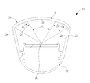
- FIG. 2 is a cross-sectional diagram of the light tube in FIG. 1 along a sectional line A-A′.
- FIG. 3 is an enlarged diagram of a transparent cover in FIG. 2 .
- FIG. 1 is a diagram of a light tube 10 according to an embodiment of the present invention.
- FIG. 2 is a cross-sectional diagram of the light tube 10 in FIG. 1 along a sectional line A-A′.
- the light tube 10 includes a tube body 12 , at least one light emitting diode 14 (one shown in FIG. 2 , but not limited thereto), and a transparent cover 16 .
- the tube body 12 includes other tube components (e.g. a heat dissipating structure and a lamp plug) of a common light emitting diode tube besides a light emitting diode and a transparent cover.
- the light emitting diode 14 can be assembled with the tube body 12 and used as a light source for emitting sufficient light to the transparent cover 16 .
- the related description for the components of the tube body 12 and the electrical connection and trace designs between the light emitting diode 14 and the tube body 12 it is commonly seen in the prior art and therefore omitted herein.
- FIG. 3 is an enlarged diagram of the transparent cover 16 in FIG. 2 .
- the transparent cover 16 is disposed on the tube body 12 to cover the light emitting diode 14 .
- the transparent cover 16 is preferably made of light scattering material with a haze greater than 70% (but not limited thereto) for further enhancing its light scattering effect, so as to make light passing through the transparent cover 16 have a more uniform brightness distribution.
- the transparent cover 16 has a roof portion 18 and two side arm portions 20 to cooperatively form a U-shaped cover structure.
- the roof portion 18 could be an arc-shaped structure, a radius of which falls within a range between 1 ⁇ m and 1000 ⁇ m, for providing approximately planar illumination when light is incident into the roof portion 18 , but not limited thereto. That is, in another embodiment, the roof portion 18 could be a planar structure. As for which structural design is utilized, it depends on the practical illumination application of the light tube 10 .
- a first microstructure region 22 and a second microstructure region 24 are formed on a surface of the roof portion 18 corresponding to the light emitting diode 14 .
- the second microstructure region 24 extends from two ends of the first microstructure region 22 .
- Each side arm portion 20 could be a planar structure, and a third microstructure region 26 is formed on a surface of each side arm portion 20 corresponding to the light emitting diode 14 . More specified, said surface of the side arm portion 20 faces the light emitting diode 14 .
- a microstructure density of the first microstructure region 22 could be greater than or equal to a microstructure density of the second microstructure region 24
- the microstructure density of the second microstructure region 24 could be greater than or equal to a microstructure density of the third microstructure region 26 .
- the microstructure density of the first microstructure region 22 is preferably greater than the microstructure density of the second microstructure region 24
- the microstructure density of the second microstructure region 24 is preferably greater than the microstructure density of the third microstructure region 26 . That is, the aforesaid microstructures are sequentially formed on the transparent cover 16 from the roof portion 18 to the side arm portion 20 in a from-dense-to-sparse manner.
- a central angle ⁇ of the first microstructure region 22 relative to the light emitting diode 14 is preferably less than or equal to 40°.
- a sum of central angles ⁇ 1 , ⁇ 2 of two sections of the second microstructure region 24 respectively extending from two ends of the first microstructure region 22 preferably falls within a range between 41° and 80° but not limited thereto.
- the aforesaid central angles of the first microstructure region 22 and the second microstructure region 24 relative to the light emitting diode 14 are adjustable according to the practical illumination application of the light tube 10 .
- the transparent cover 16 could have sawtooth-shaped bar microstructures formed thereon for further enhancing the light scattering effect of the transparent cover 16 .
- the first microstructure region 22 could include a plurality of first sawtooth-shaped bar structures 28
- the second microstructure region 24 could include a plurality of second sawtooth-shaped bar structures 30
- the third microstructure region 26 could include a plurality of third sawtooth-shaped bar structures 32 .
- a vertex angle of each first sawtooth-shaped bar structure 28 preferably falls within a range between 70° and 90°.
- a vertex angle of each second sawtooth-shaped bar structure 30 preferably falls within a range between 90° and 120°.
- a vertex angle of each third sawtooth-shaped bar structure 32 preferably falls within a range between 120° and 150°.
- the light scattering effect of the transparent cover 16 could be further enhanced after light emitted by the light emitting diode 14 is incident into the first microstructure region 22 , the second microstructure region 24 , and the third microstructure region 26 . Accordingly, the light emitting angle of the light tube 10 could be increased and light emitted out of the transparent cover 16 could have a more uniform brightness distribution.
- the microstructure design of the transparent cover 16 is not limited to the aforesaid embodiment.
- all microstructure designs for light scattering enhancement could be utilized by the present invention.
- the first, second, and third microstructure regions 22 , 24 , 26 could have a plurality of first, second, and third arc-shaped bar structures respectively.
- a radius of each second arc-shaped bar structure is preferably less than or equal to a radius of each first arc-shaped bar structure and is preferably greater than a radius of each third arc-shaped bar structure. That is, the aforesaid arc-shaped bar structures are distributed sequentially from the roof portion 18 to the side arm portions 20 of the transparent cover 16 with the gradually-decreasing radiuses.
- the present invention could also utilize the design in which the microstructures of different shapes (e.g. the tooth-shaped bar structures and the arc-shaped bar structures) are formed on different microstructure regions respectively or one microstructure region, to improve flexibility of the transparent cover 16 in its structural design.
- the microstructures of different shapes e.g. the tooth-shaped bar structures and the arc-shaped bar structures
- the present invention utilizes the structural designs of the roof portion and the side arm portion of the transparent cover and the design in which the microstructures are distributed sequentially from the roof portion to the side arm portions in a from-dense-to-sparse manner, to make the transparent cover capable of providing approximately planar illumination and having a light scattering enhancement effect, so that the light emitting angle of the light tube could be increased and light emitted out of the transparent cover could have a more uniform brightness distribution.
- the light tube provided by the present invention could not only have a planar illumination function (or an approximately illumination function), but also solve the prior art problem that a light tube has a poor visual effect due to uneven brightness distribution on an approximately planar cover. Accordingly, the illumination quality of the light tube provided by the present invention could be greatly improved.
Abstract
Description
Claims (14)
Applications Claiming Priority (3)
| Application Number | Priority Date | Filing Date | Title |
|---|---|---|---|
| TW101223833U TWM452309U (en) | 2012-12-07 | 2012-12-07 | Light tube |
| TW101223833U | 2012-12-07 | ||
| TW101223833 | 2012-12-07 |
Publications (2)
| Publication Number | Publication Date |
|---|---|
| US20140160743A1 US20140160743A1 (en) | 2014-06-12 |
| US8870409B2 true US8870409B2 (en) | 2014-10-28 |
Family
ID=49078763
Family Applications (1)
| Application Number | Title | Priority Date | Filing Date |
|---|---|---|---|
| US13/864,276 Expired - Fee Related US8870409B2 (en) | 2012-12-07 | 2013-04-17 | Light tube |
Country Status (2)
| Country | Link |
|---|---|
| US (1) | US8870409B2 (en) |
| TW (1) | TWM452309U (en) |
Cited By (3)
| Publication number | Priority date | Publication date | Assignee | Title |
|---|---|---|---|---|
| US20150098206A1 (en) * | 2013-10-03 | 2015-04-09 | Cree, Inc. | Led lamp |
| US20170059122A1 (en) * | 2015-08-27 | 2017-03-02 | Hon Hai Precision Industry Co., Ltd. | Lens and light-emitting device employing same |
| US11864547B2 (en) * | 2017-01-10 | 2024-01-09 | Seoul Viosys Co., Ltd. | Adhesive-type insect trap having a cover with a light refracting portion formed thereon |
Families Citing this family (4)
| Publication number | Priority date | Publication date | Assignee | Title |
|---|---|---|---|---|
| RU2700182C2 (en) * | 2015-05-18 | 2019-09-13 | Филипс Лайтинг Холдинг Б.В. | Tubular light-emitting device |
| CN206514116U (en) * | 2016-12-05 | 2017-09-22 | 欧普照明股份有限公司 | A kind of light source module and light fixture |
| IT201800006340A1 (en) * | 2018-06-18 | 2019-12-18 | LED ILLUMINATING BODY | |
| ES2936957B2 (en) * | 2021-09-21 | 2023-08-31 | Daisalux S A U | Emergency luminaire |
Citations (4)
| Publication number | Priority date | Publication date | Assignee | Title |
|---|---|---|---|---|
| US20110175536A1 (en) * | 2008-08-11 | 2011-07-21 | Toshiyuki Fujita | Lighting device |
| US8038322B2 (en) * | 2008-04-24 | 2011-10-18 | Yancheng Haomai Lighting Science & Technology Co., Ltd. | Tubular LED lighting device |
| US20130128577A1 (en) * | 2011-11-17 | 2013-05-23 | Hon Hai Precision Industry Co., Ltd. | Light source module and illuminating device |
| US8454206B2 (en) * | 2010-07-26 | 2013-06-04 | Hon Hai Precision Industry Co., Ltd. | Surface light source device |
-
2012
- 2012-12-07 TW TW101223833U patent/TWM452309U/en not_active IP Right Cessation
-
2013
- 2013-04-17 US US13/864,276 patent/US8870409B2/en not_active Expired - Fee Related
Patent Citations (4)
| Publication number | Priority date | Publication date | Assignee | Title |
|---|---|---|---|---|
| US8038322B2 (en) * | 2008-04-24 | 2011-10-18 | Yancheng Haomai Lighting Science & Technology Co., Ltd. | Tubular LED lighting device |
| US20110175536A1 (en) * | 2008-08-11 | 2011-07-21 | Toshiyuki Fujita | Lighting device |
| US8454206B2 (en) * | 2010-07-26 | 2013-06-04 | Hon Hai Precision Industry Co., Ltd. | Surface light source device |
| US20130128577A1 (en) * | 2011-11-17 | 2013-05-23 | Hon Hai Precision Industry Co., Ltd. | Light source module and illuminating device |
Cited By (5)
| Publication number | Priority date | Publication date | Assignee | Title |
|---|---|---|---|---|
| US20150098206A1 (en) * | 2013-10-03 | 2015-04-09 | Cree, Inc. | Led lamp |
| US9541241B2 (en) * | 2013-10-03 | 2017-01-10 | Cree, Inc. | LED lamp |
| US20170059122A1 (en) * | 2015-08-27 | 2017-03-02 | Hon Hai Precision Industry Co., Ltd. | Lens and light-emitting device employing same |
| US9909735B2 (en) * | 2015-08-27 | 2018-03-06 | Hon Hai Precision Industry Co., Ltd. | Lens and light-emitting device employing same |
| US11864547B2 (en) * | 2017-01-10 | 2024-01-09 | Seoul Viosys Co., Ltd. | Adhesive-type insect trap having a cover with a light refracting portion formed thereon |
Also Published As
| Publication number | Publication date |
|---|---|
| US20140160743A1 (en) | 2014-06-12 |
| TWM452309U (en) | 2013-05-01 |
Similar Documents
| Publication | Publication Date | Title |
|---|---|---|
| US8870409B2 (en) | Light tube | |
| US9500323B2 (en) | Lens for LED illumination | |
| US9068716B2 (en) | Illumination apparatus | |
| CN101725905B (en) | Light-emitting diode lamp | |
| US8035899B2 (en) | Lens assembly | |
| US20150043213A1 (en) | Lens and an illumination device having the lens | |
| US9371976B2 (en) | Illumination apparatus | |
| JP2014150049A5 (en) | ||
| US20120161610A1 (en) | Light Extraction Block with Curved Surface | |
| CN105556355A (en) | Light diffusing lens and light emitting device having same | |
| CN104334959A (en) | Lighting device having a remote wave length converting layer | |
| US20130114267A1 (en) | Converging illuminant device | |
| CN103137823B (en) | Light-emitting diode and apply the direct-light-type backlight of this light-emitting diode | |
| US20140306246A1 (en) | Light source module | |
| US20130148372A1 (en) | Light guide device for vehicle | |
| US9388957B2 (en) | Secondary optical element and light source module | |
| JP2014026000A (en) | Emblem light-emitting device | |
| CN104421691A (en) | Light-emitting diode module | |
| US20130272025A1 (en) | Lighting device and cove lighting module using the same | |
| US20140029305A1 (en) | Light source module | |
| TW201321667A (en) | Light source module and light emitting device having same | |
| US20140022820A1 (en) | Ring-shaped light guiding member and backlight module having same | |
| US20130201719A1 (en) | Front light module | |
| Riedel et al. | Extracting and shaping the light of OLED devices | |
| US20150292710A1 (en) | Lamp structure |
Legal Events
| Date | Code | Title | Description |
|---|---|---|---|
| AS | Assignment |
Owner name: DONGGUAN MASSTOP LIQUID CRYSTAL DISPLAY CO., LTD., Free format text: ASSIGNMENT OF ASSIGNORS INTEREST;ASSIGNORS:YE, ZHI-TING;LIN, MING-CHUAN;CHANG, HUNG-PIN;AND OTHERS;REEL/FRAME:030228/0619 Effective date: 20130416 Owner name: WINTEK CORPORATION, TAIWAN Free format text: ASSIGNMENT OF ASSIGNORS INTEREST;ASSIGNORS:YE, ZHI-TING;LIN, MING-CHUAN;CHANG, HUNG-PIN;AND OTHERS;REEL/FRAME:030228/0619 Effective date: 20130416 |
|
| STCF | Information on status: patent grant |
Free format text: PATENTED CASE |
|
| FEPP | Fee payment procedure |
Free format text: MAINTENANCE FEE REMINDER MAILED (ORIGINAL EVENT CODE: REM.) |
|
| FEPP | Fee payment procedure |
Free format text: ENTITY STATUS SET TO SMALL (ORIGINAL EVENT CODE: SMAL); ENTITY STATUS OF PATENT OWNER: SMALL ENTITY |
|
| FEPP | Fee payment procedure |
Free format text: SURCHARGE FOR LATE PAYMENT, SMALL ENTITY (ORIGINAL EVENT CODE: M2554); ENTITY STATUS OF PATENT OWNER: SMALL ENTITY |
|
| MAFP | Maintenance fee payment |
Free format text: PAYMENT OF MAINTENANCE FEE, 4TH YR, SMALL ENTITY (ORIGINAL EVENT CODE: M2551); ENTITY STATUS OF PATENT OWNER: SMALL ENTITY Year of fee payment: 4 |
|
| FEPP | Fee payment procedure |
Free format text: MAINTENANCE FEE REMINDER MAILED (ORIGINAL EVENT CODE: REM.); ENTITY STATUS OF PATENT OWNER: SMALL ENTITY |
|
| LAPS | Lapse for failure to pay maintenance fees |
Free format text: PATENT EXPIRED FOR FAILURE TO PAY MAINTENANCE FEES (ORIGINAL EVENT CODE: EXP.); ENTITY STATUS OF PATENT OWNER: SMALL ENTITY |
|
| STCH | Information on status: patent discontinuation |
Free format text: PATENT EXPIRED DUE TO NONPAYMENT OF MAINTENANCE FEES UNDER 37 CFR 1.362 |
|
| FP | Lapsed due to failure to pay maintenance fee |
Effective date: 20221028 |