US8867537B1 - Method and system for processing network packets - Google Patents
Method and system for processing network packets Download PDFInfo
- Publication number
- US8867537B1 US8867537B1 US13/610,095 US201213610095A US8867537B1 US 8867537 B1 US8867537 B1 US 8867537B1 US 201213610095 A US201213610095 A US 201213610095A US 8867537 B1 US8867537 B1 US 8867537B1
- Authority
- US
- United States
- Prior art keywords
- buffer
- pdu
- computing system
- eddp
- tagged
- Prior art date
- Legal status (The legal status is an assumption and is not a legal conclusion. Google has not performed a legal analysis and makes no representation as to the accuracy of the status listed.)
- Active, expires
Links
Images


Classifications
-
- H—ELECTRICITY
- H04—ELECTRIC COMMUNICATION TECHNIQUE
- H04L—TRANSMISSION OF DIGITAL INFORMATION, e.g. TELEGRAPHIC COMMUNICATION
- H04L45/00—Routing or path finding of packets in data switching networks
-
- G—PHYSICS
- G06—COMPUTING; CALCULATING OR COUNTING
- G06F—ELECTRIC DIGITAL DATA PROCESSING
- G06F11/00—Error detection; Error correction; Monitoring
- G06F11/07—Responding to the occurrence of a fault, e.g. fault tolerance
- G06F11/08—Error detection or correction by redundancy in data representation, e.g. by using checking codes
- G06F11/10—Adding special bits or symbols to the coded information, e.g. parity check, casting out 9's or 11's
- G06F11/1004—Adding special bits or symbols to the coded information, e.g. parity check, casting out 9's or 11's to protect a block of data words, e.g. CRC or checksum
-
- H—ELECTRICITY
- H04—ELECTRIC COMMUNICATION TECHNIQUE
- H04L—TRANSMISSION OF DIGITAL INFORMATION, e.g. TELEGRAPHIC COMMUNICATION
- H04L1/00—Arrangements for detecting or preventing errors in the information received
- H04L1/12—Arrangements for detecting or preventing errors in the information received by using return channel
- H04L1/16—Arrangements for detecting or preventing errors in the information received by using return channel in which the return channel carries supervisory signals, e.g. repetition request signals
- H04L1/1607—Details of the supervisory signal
- H04L1/1671—Details of the supervisory signal the supervisory signal being transmitted together with control information
-
- H—ELECTRICITY
- H04—ELECTRIC COMMUNICATION TECHNIQUE
- H04L—TRANSMISSION OF DIGITAL INFORMATION, e.g. TELEGRAPHIC COMMUNICATION
- H04L1/00—Arrangements for detecting or preventing errors in the information received
- H04L1/12—Arrangements for detecting or preventing errors in the information received by using return channel
- H04L1/16—Arrangements for detecting or preventing errors in the information received by using return channel in which the return channel carries supervisory signals, e.g. repetition request signals
- H04L1/18—Automatic repetition systems, e.g. Van Duuren systems
- H04L1/1829—Arrangements specially adapted for the receiver end
- H04L1/1835—Buffer management
-
- H—ELECTRICITY
- H04—ELECTRIC COMMUNICATION TECHNIQUE
- H04L—TRANSMISSION OF DIGITAL INFORMATION, e.g. TELEGRAPHIC COMMUNICATION
- H04L49/00—Packet switching elements
- H04L49/90—Buffering arrangements
- H04L49/9063—Intermediate storage in different physical parts of a node or terminal
-
- H—ELECTRICITY
- H04—ELECTRIC COMMUNICATION TECHNIQUE
- H04L—TRANSMISSION OF DIGITAL INFORMATION, e.g. TELEGRAPHIC COMMUNICATION
- H04L67/00—Network arrangements or protocols for supporting network services or applications
- H04L67/01—Protocols
- H04L67/10—Protocols in which an application is distributed across nodes in the network
- H04L67/1097—Protocols in which an application is distributed across nodes in the network for distributed storage of data in networks, e.g. transport arrangements for network file system [NFS], storage area networks [SAN] or network attached storage [NAS]
-
- H—ELECTRICITY
- H04—ELECTRIC COMMUNICATION TECHNIQUE
- H04L—TRANSMISSION OF DIGITAL INFORMATION, e.g. TELEGRAPHIC COMMUNICATION
- H04L69/00—Network arrangements, protocols or services independent of the application payload and not provided for in the other groups of this subclass
- H04L69/22—Parsing or analysis of headers
-
- H—ELECTRICITY
- H04—ELECTRIC COMMUNICATION TECHNIQUE
- H04L—TRANSMISSION OF DIGITAL INFORMATION, e.g. TELEGRAPHIC COMMUNICATION
- H04L45/00—Routing or path finding of packets in data switching networks
- H04L45/74—Address processing for routing
- H04L45/742—Route cache; Operation thereof
-
- H—ELECTRICITY
- H04—ELECTRIC COMMUNICATION TECHNIQUE
- H04L—TRANSMISSION OF DIGITAL INFORMATION, e.g. TELEGRAPHIC COMMUNICATION
- H04L49/00—Packet switching elements
- H04L49/90—Buffering arrangements
- H04L49/9021—Plurality of buffers per packet
Definitions
- the present disclosure relates to network and storage systems.
- Computer networks are commonly used to send and receive network information.
- Various protocols and standards are typically used to send and receive the network information.
- information is sent and received as network packets, frames, protocol data units (PDUs) and other units.
- PDUs protocol data units
- a method for writing information to a first memory location controlled by a first computing system from a second memory location controlled by a second computing system that interfaces with the first computing system via a network connection comprises: (a) registering the first memory location with a first adapter interfacing with the first computing system; (b) providing a first identifier for uniquely identifying the first memory location; wherein the first adapter provides the first identifier to the first computing system; (c) notifying the second computing system of the first memory location by using the first identifier with a write request for writing information from the second memory location directly to the first memory location; (d) registering the second memory location with a second adapter interfacing with the second computing system; (e) providing a second identifier for uniquely identifying the second memory location; wherein the second adapter provides the second identifier to the second computing system; (f) creating a tagged protocol data unit (“PDU”) for transferring information directly from the second memory location to the first memory location; wherein the tagged PDU
- PDU protocol data unit
- a method for writing information to a first memory location controlled by a first computing system from a second memory location controlled by a second computing system that interfaces with the first computing system via a network connection comprises: (a) registering the first memory location with a first adapter interfacing with the first computing system; (b) providing a first identifier for uniquely identifying the first memory location; wherein the first adapter provides the first identifier to the first computing system; (c) notifying the second computing system of the first memory location by using the first identifier with a write request for writing information from the second memory location directly to the first memory location; (d) registering the second memory location with a second adapter interfacing with the second computing system; (e) providing a second identifier for uniquely identifying the second memory location; wherein the second adapter provides the second identifier to the second computing system; (f) creating a tagged protocol data unit (“PDU) for transferring information directly from the second memory location to the first memory location; wherein the tagged PDU
- PDU tagged protocol data
- FIG. 1 shows a block diagram of a system for sending and receiving network information, according to one embodiment
- FIG. 2 shows a block diagram of a network interface card, according to one embodiment
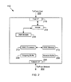
- FIG. 3 shows a block diagram of memory system layout, according to one embodiment
- FIG. 4 shows a RDMA protocol layered architecture used according to one embodiment
- FIG. 5 shows a EDDP architecture, according to one embodiment
- FIG. 6 shows a layout of EDDP layered below RDMA and above DCB Ethernet, according to one embodiment
- FIG. 7 shows an example of EDDP header fields, according to one embodiment
- FIGS. 8-13 provide examples of some of the PDU formats, according to the adaptive embodiments of the present disclosure.
- FIG. 14 shows a process/system diagram for performing a RDMA write operation using the EDDP protocol, according to one embodiment
- FIG. 15 shows a process flow diagram for performing the RDMA write operation using the EDDP protocol, according to one embodiment
- FIGS. 16 and 17 show a system/process diagram for performing a read operation using EDDP, according to one embodiment
- FIG. 18 shows a process flow diagram for sending a message using EDDP, according to one embodiment
- FIG. 19 shows a process flow for sending a NACK PDU from one host to another host.
- FIG. 20 shows a process flow diagram for managing a send timer event, according to one embodiment.
- FIG. 1 shows a block diagram of a system 100 for sending and receiving network information, according to one embodiment.
- System 100 may include a first computing system (or device) 102 (also referred to as host system 102 , Host 1 or Host System 1) and a second computing system (or device) 116 (also referred to as host system 116 , Host 2 or Host System 2) communicating via a connection 114 .
- Connection 114 may be a network connection. In one embodiment, connection 114 may be an Ethernet connection.
- Host systems typically include several functional components. These components may include a central processing unit (CPU) (also referred to as “processor”) (for example, 104 and 118 ), main memory (for example, 106 and 120 ) (also referred to as host memory), input/output (“I/O”) devices (not shown), and other devices, for example, a storage device or media.
- CPU central processing unit
- main memory for example, 106 and 120
- I/O input/output
- other devices for example, a storage device or media.
- the main memory ( 106 and 120 ) is coupled to the CPU ( 104 and 118 ) via a system bus ( 108 and 122 ) or a local memory bus.
- the main memory is used to provide the CPU ( 104 , 118 ) access to data and/or program information that is stored in the main memory ( 106 , 120 ) at execution time.
- the main memory is composed of random access memory (RAM) circuits.
- RAM random access memory
- Host system 102 communicates with host system 116 via a network interface card (NIC) 112 .
- NIC network interface card
- a NIC that is able to transfer data from host system memory directly to host system memory of host system 116 is referred to as RNIC (as shown in FIG. 1 ) and is compliant with the Ethernet Direct Data Placement (EDDP) format, according to one embodiment, may be referred to as EENIC (or RNIC).
- NIC network interface card
- a RNIC interface (for example, 110 , 124 ) interfaces between a processor ( 104 , 118 ) and a RNIC ( 112 , 126 ).
- Computing systems and devices typically use various protocols/standards for network communication.
- the following provides a brief introduction to some of the standards/protocols:
- TCP Transmission Control Protocol/Internet Protocol
- TCP/IP Transmission Control Protocol/Internet Protocol
- TCP is a network protocol that provides connection-oriented, reliable, byte stream service.
- two network nodes which includes network device and networked computing systems, may establish a logical connection before sending data.
- TCP maintains state information regarding the data transfer and data is delivered in the same order that it was sent.
- a byte stream service means that TCP views data to be sent as a continuous data stream that is sent in any way it sees fit and delivers it to the remote node as a byte stream.
- IP The IP standard protocol provides a datagram service whose function is to enable routing of data through various network subnets. Each of these subnets could be a different physical link such as Ethernet, ATM, or others. IP is also responsible for fragmentation of transmit data to match a local link's maximum transmission unit (MTU). IP can fragment data at a source node or at any intervening router between the source and a destination node.
- MTU maximum transmission unit
- RDMA Remote Direct Memory Access
- UDP upper layer protocol
- RDMA over TCP/IP defines the interoperable protocols to support RDMA operations over standard TCP/IP networks.
- RDMA may also be interchangeably referred to as “RDMAP” throughout the specification and drawings.
- DDP means the Direct Data Placement (DDP) protocol that allows one to place data received by a computing system directly into an upper layer protocol (ULP) buffer without using intermediate buffers.
- the RDMA/DDP protocol typically uses a reliable system, for example, TCP/IP.
- TCP/IP Transmission Control Protocol
- the adaptive embodiments disclosed herein solve this problem by providing a new protocol called Ethernet Direct Data Placement (“EDDP”) that is described below in detail.
- EDDP Ethernet Direct Data Placement
- Enhanced Ethernet Enhanced Ethernet or Data Center Bridging Ethernet (DCB) is a new protocol that is being proposed for use in storage area networks and other applications. DCB however lacks the reliability of TCP/IP. To effectively use DCB with RDMA/DDP, a new protocol/format is needed so that one can use the advantages of RDMA/DDP. In one embodiment, EDDP is proposed for using RDMA/DDP with DCB.
- DCB Data Center Bridging Ethernet
- EDDP is a proposed new protocol, according to one embodiment.
- EDDP may enable a ULP to send information to a Data Sink (a network device/system that receives information, for example, Host System 1, 102 , FIG. 1 ) without having the Data Sink to place the data in an intermediate buffer.
- a Data Sink a network device/system that receives information, for example, Host System 1, 102 , FIG. 1
- RNIC 112 can place the data directly to an assigned ULP buffer.
- host system 102 consumes less memory bandwidth than a “buffered mode” where host system 102 moves data from an intermediate buffer to the final destination, i.e. host memory 108 .
- EDDP preserves ULP record boundaries (messages) while providing a variety of data transfer mechanisms and completion mechanisms to be used to transfer ULP messages.
- EDDP uses DCB as its Lower Level Transport instead of TCP/IP.
- RNIC 112 receives and sends network packets 202 via a network interface 204 and a network connection 114 ( FIG. 1 ).
- the structure of network interface 204 depends on the type of protocol and network environment.
- a receive buffer 206 is used to store packets as soon as they are received.
- Outgoing buffer 208 is used to stage packets before being sent to the network.
- Host interface 218 is used to interface with a host system via a bus 220 .
- bus 220 may be a PCI, PCI-X, PCI-Express or any other type of bus.
- a direct memory access (DMA) module 216 sends DMA requests to an arbitration module (or Arbiter) 214 to access bus 220 for sending data to the host system.
- Arbitration module 214 arbitrates between competing requests and grants bus access to a request that wins the arbitration scheme.
- Processor (may also be referred to as RNIC processor) 212 executes instructions out of RNIC memory 210 .
- RNIC processor may also be referred to as RNIC processor
- more than one processor 212 may be used to send and receive network information.
- a separate processor or state machine
- another processor or state machine
- RNIC 112 may be used to handle outgoing operations (i.e. packets transmitted by RNIC 112 ).
- FIG. 3 shows a block diagram of memory system layout both at the host system level and the RNIC level.
- Host system 112 may allocate a buffer 106 A (shown as Buffer 1) that can receive data directly from host 116 via RNIC 112 in a “tagged buffer” mode.
- RNIC 112 may maintain a send timer list 210 A and a buffer registration table 210 B that are described below.
- Anonymous buffer 106 B is also maintained to receive data in an “untagged buffer mode” as described below.
- Host system 116 maintains a Buffer 120 A (shown as Buffer 2 ) from where data is sent directly via RNIC 126 to host system 102 .
- RNIC 126 also maintains a send timer list 124 A and a buffer registration table 124 B that is described below.
- Host system 116 also maintains anonymous buffers 120 B, similar to host system 102 .
- EDDP supports two types of data transfer processes “Tagged Buffer” mode and “Untagged Buffer” mode.
- a Data Sink for example, Host 102 receiving data from host 116
- sends an identifier referred to as a Steering Tag (STag)
- STag Steering Tag
- ULP buffer for example, Buffer 1, 106 A ( FIG. 3 )
- the STag is transferred to the Data Source using a ULP defined method.
- the Data Source ULP has a STag for a destination ULP buffer, it can request that the EDDP layer send the ULP data directly to the destination ULP buffer by specifying the STag to EDDP.
- the Tagged Buffer, 106 A does not have to be filled starting at the beginning of the ULP buffer.
- the ULP Data Source can provide an arbitrary offset into the ULP buffer.
- the Untagged Buffer Mode uses anonymous buffers (for example, 106 B and 120 B, FIG. 3 ) and enables data transfer without having the Data Sink to Advertise a ULP Buffer to the Data Source.
- the Data Sink queues up a series of receive ULP buffers.
- An Untagged EDDP Message from the Data Source consumes an Untagged Buffer (for example, 106 B) at the Data Sink. Because EDDP is message oriented, even if the Data Source sends an EDDP Message payload smaller than the receive ULP buffer, the partially filled receive ULP buffer is Delivered to the ULP anyway.
- the Tagged and Untagged Buffer Mode are different in the following manner:
- the Data Source specifies which received Tagged Buffer will be used for a specific Tagged EDDP Message (sender-based ULP buffer management).
- the Data Sink specifies the order in which Untagged Buffers are consumed as Untagged EDDP Messages are received (receiver-based ULP buffer management).
- the ULP at the Data Sink advertises the ULP buffer to the Data Source through a ULP specific mechanism before data transfer can occur.
- the Untagged Buffer Mode data transfer can occur without an end-to-end explicit ULP buffer Advertisement.
- an EDDP Message can start at an arbitrary offset within the Tagged Buffer.
- an EDDP Message starts at offset 0.
- the Tagged Buffer Mode allows multiple EDDP Messages targeted to a Tagged Buffer with a single ULP buffer Advertisement.
- the Untagged Buffer Mode associates a receive ULP buffer for each EDDP Message targeted to an Untagged Buffer.
- Either data transfer Mode places a ULP Message into an EDDP Message.
- Each EDDP Message is then sliced into EDDP PDUs that are intended to fit within the Ethernet layers Maximum Transmission Unit.
- the ULP can post arbitrary size ULP Messages, including up to 2 ⁇ 32 ⁇ 1 octets of ULP Payload, and EDDP slices the ULP message into EDDP PDUs which are reassembled transparently at the Data Sink.
- the DDP layer provides in-order Delivery for the ULP.
- EDDP differentiates between Data Delivery and Data Placement.
- EDDP provides enough information in each EDDP PDU to allow the ULP Payload in each inbound EDDP PDU to be directly placed into the correct ULP Buffer, even when the EDDP PDUs arrive out-of-order.
- EDDP enables the reassembly of ULP Payload contained in EDDP PDUs of an EDDP Message into a ULP Message to occur within the ULP Buffer, thus eliminating the traditional copy out of the reassembly buffer into the ULP Buffer.
- An EDDP Message's payload is delivered to the ULP when: (a) All EDDP PDUs of an EDDP Message have been received and the payload of the EDDP Message has been placed into the associated ULP Buffer; (b) All prior EDDP Messages have been placed, and (c) All prior EDDP message deliveries have been performed.
- FIG. 4 shows a layered architecture 400 using TCP/IP with RDMA and DDP.
- Layered architecture 400 includes Ethernet 402 for network connectivity.
- TCP layer 406 and IP layer 404 are used as the transport layers.
- SCTP (Stream Control Transmission Protocol) 405 may also be used as a transmission protocol.
- MPA layer 408 is above the TCP layer 406 .
- RDMA 412 also referred to as RDMAP 412
- DDP 410 are used to place data directly into a host memory.
- ULP 414 is an upper layer protocol. In one example, ULP 414 may be an operating system of a computing system.
- Architecture 400 has disadvantages. For example, handling TCP/IP traffic may slow overall data processing and hence is undesirable.
- the various embodiments disclosed herein overcome these shortcomings by not using TCP/IP and instead using EDDP.
- FIG. 5 shows EDDP architecture 500 , according to one embodiment.
- EDDP structure does not have to use TCP/IP.
- EDDP architecture 500 may include data center bridging Ethernet (also referred to as “DCB Ethernet”) 502 as the network protocol.
- DCB Ethernet data center bridging Ethernet
- EDDP 504 replaces the transport protocol.
- RDMA 506 is layered above EDDP 504 .
- ULP 508 is an upper layer protocol using RDMA, while ULP 510 may not use RDMA.
- FIG. 6 shows a layout 600 of the various headers when EDDP is layered below RDMA and above DCB Ethernet, as shown in FIG. 5 .
- Layout 600 includes Ethernet cyclic redundancy code (CRC) 602 and EDDP CRC 604 , used for error checking.
- the RDMA payload 606 is accompanied by a RDMA header 608 .
- Layout 600 also includes an EDDP header 610 and an Ethernet header 612 .
- Ethernet header 612 is a standard header used for Ethernet based network communication.
- the EDDP header 610 is shown in FIG. 7 and described below.
- FIG. 7 shows an example of EDDP header 610 fields that may be used, according to one embodiment.
- the various EDDP header fields are described below:
- the OpCode field 702 indicates an EDDP PDU type identified by the PDU Type unique fields 708 . Examples of EDDP PDU Types are as follows:
- Payload_Length 704 The Payload_Length 704 field provides a size of ULP data included in an EDDP PDU.
- Control field 706 may include several fields/flags, for example:
- a Last flag (“L”) which specifies whether an EDDP PDU is a Last PDU of an EDDP Message. If the Last flag is set to a certain value, for example, one, the EDDP Message payload is delivered to a ULP after placement of all EDDP PDUs of a current EDDP Message and all prior EDDP Messages. If the Last flag is set to another value, for example, zero, the EDDP PDU is considered as an intermediate EDDP PDU.
- R Acknowledgement Request Flag
- the R bit may be set to 1 on a last PDU of a ULP Message to “Request” an Acknowledgement from a remote host system indicating that the message was successfully received.
- N/I flag depends on a PDU OpCode type, for example:
- Untagged/Tagged Buffer PDU If the PDU type is Untagged or Tagged Buffer type then this flag may indicate if the PDU is an initial PDU of an Untagged/Tagged Message.
- Untagged/Tagged Message Acknowledgement PDU If the PDU type is an Untagged/Tagged Message Acknowledgement then this flag may be used to indicate if the PDU is an Acknowledgement or a Negative Acknowledgement of an Untagged or Tagged Message.
- the N flag may indicate that an Acknowledgement PDU is a “Negative Acknowledgement” by a receiving EDDP host system that has not received a ULP message indicated by a Message Sequence Number field.
- Finished Flag (“F”): The F flag when set may indicate that an originating EDDP host system is finished with half of an EDDP connection and requests a remote host to close its half of the connection.
- ULP Reserved Field 714 is opaque to the EDDP protocol and may be structured in any way by a ULP.
- EDDP may set the ULP Reserved Field 714 to a value specified by the ULP. It is transferred unmodified from the Data Source to a Data Sink.
- EDDP provides the ULP Reserved field 714 to the ULP when the EDDP Message is delivered.
- Each EDDP PDU within a specific EDDP Message includes the same value for this field.
- the Data Source ensures that each EDDP PDU within a specific EDDP Message includes the same value for this field.
- the PAD field 710 trails the ULP PDU and may be between zero and a certain size, for example, three octets of data.
- the pad data may be set to zero by a sender and ignored by the receiver (except for CRC checking).
- the length of the pad may be set so as to make the size of the EDDP PDU an integral multiple of four.
- CRC 712 may include a check value, which may be used to verify the contents of an EDDP PDU.
- FIGS. 8-13 provide examples of some of the PDU formats, according to the adaptive embodiments of the present disclosure.
- FIG. 8 shows a block diagram of an EDDP Tagged Buffer PDU structure 800 .
- Some fields (for example, PAD 822 and CRC 824 ) in the EDDP Tagged Buffer PDU structure 800 are similar to the EDDP header 610 fields (for example, PAD 710 and CRC 712 ) shown in FIG. 7 and described above.
- the various fields of PDU structure 800 are described below:
- Payload_Length (unsigned integer) 802 The Payload_Length field 802 provides a size of the ULP data included in an EDDP PDU. The size may be provided in number of octets.
- L 804 means a “Last” PDU flag: The L bit 804 may be reset to zero on intermediate PDUs of a ULP Message sequence. The L bit may be set to 1 on the last PDU of the ULP Message
- R 806 means an Acknowledgement Request flag.
- the R bit 806 may be set to zero on intermediate PDUs of a ULP Message sequence.
- the R bit may be set to 1 on the last PDU of the ULP Message to “Request” an Acknowledgement from another system.
- I 808 means an “Initial” PDU flag.
- the I flag 808 may be set to 1 on a first PDU of a Tagged Buffer Message.
- the I flag 808 may be reset on intermediate PDUs and a last PDU of a Tagged Buffer Message.
- OpCode 810 for a Tagged Buffer PDU may be set to a certain value, for example, 0x2.
- Rsrvd ULP Reserved
- Destination Connection Handle 814 is a field that includes a “Connection Handle” passed by a remote system during connection establishment. The remote system uses this field to identify a context of a connection.
- STag 816 is a Steering Tag that identifies a Data Sink's Tagged Buffer (for example, 106 A) and is associated with an EDDP Connection.
- STag 816 is set by EDDP to a value specified by the ULP.
- the EDDP provides the STag field when the ULP Message is received.
- Each EDDP PDU within a specific EDDP Message includes the same value for this field and the value is supplied by the ULP.
- the Data Source ensures that each EDDP PDU within a specific EDDP Message includes the same value for this field.
- the Tagged Offset 818 specifies an offset, for example, in octets, within a Data Sink's Tagged Buffer, where the placement of a ULP Payload 820 in an EDDP PDU starts.
- An EDDP Message may start at an arbitrary Tagged Offset within a Tagged Buffer.
- FIG. 9 shows an Untagged Buffer PDU format having a plurality of fields. Some fields in the Untagged format are similar to the Tagged PDU format shown in FIG. 8 and described above. The other fields are described below.
- Payload_Length Field 902 is similar to field 802 described above with respect to FIG. 8 .
- “L” flag 904 may be set to zero on intermediate PDUs of a ULP Message or set to 1 on a last PDU of the ULP message.
- R flag 906 is an “Acknowledgement Request” flag and may be set to zero on intermediate PDUs of a ULP Message sequence. The R flag may be set to 1 on a last PDU of the ULP Message to “Request” an Acknowledgement from a remote system that the message was successfully received.
- I flag 908 is an initial flag that may be set to 1 on a first PDU of an Untagged Buffer Message.
- the I flag 908 may be reset on intermediate PDUs and for a last PDU of an Untagged Buffer Message.
- OpCode 910 for an Untagged Buffer PDU may be set to a certain value, for example, 0x3.
- ULP Rsrvd field 912 The ULP Rsrvd field 912 is opaque to the EDDP protocol and may be set by the ULP.
- EDDP may set the ULP Rsrvd Field 912 to the value specified by the ULP. It is transferred unmodified from the Data Source to a Data Sink.
- EDDP provides the ULP Rsrvd field 912 to the ULP when the ULP Message is received.
- Each EDDP PDU within a specific EDDP Message may include the same value for the ULP Rsrvd field.
- the EDDP implementation does not have to verify that the same value is present in the ULP Rsrvd field of each EDDP PDU within a specific EDDP Message and may provide the value from any one of the received EDDP PDU to the ULP when the ULP Message is delivered.
- QN 915 is a Queue Number for identifying a Data Sink's Untagged Buffer queue. For example, 0 may be used to identify a Send Queue; 1 may be used for a RDMA Read Request Queue; and 2 may be used to identify a Terminate Queue.
- Each EDDP segment within an EDDP message includes the same value for this field and which is supplied by the ULP at the Data Source.
- the Data Source ensures that each EDDP PDU within a specific EDDP Message includes the same value for this field.
- Destination Connection Handle 914 may include a Connection Handle passed by a remote system during connection establishment. The remote system uses this field to identify the context of the connection.
- Message Sequence Number 916 may be used to identify a sequence number.
- the sequence number may be increased by one (modulo 2 ⁇ 32) with each EDDP Message targeting a Queue Number of an EDDP Connection that is associated with an EDDP PDU.
- the initial value for Message Sequence Number may be one.
- the Message Sequence Number value may wrap to 0 after a value of 0xFFFFFF.
- Each EDDP segment within a specific EDDP message may include a same value for this field.
- the Data Source ensures that each EDDP PDU within an EDDP Message includes the same value for this field.
- Message Offset 918 may be used to indicate an offset, for example, in octets, from the start of an EDDP Message represented by the Message Sequence Number and Queue Number on an EDDP Connection associated with the EDDP PDU.
- the Message Offset referencing the first octet of an EDDP Message may set to zero by the EDDP layer.
- the ULP Reserved field 920 is also opaque to the EDDP protocol and can be structured in any way by the ULP.
- EDDP sets ULP Rsrvd Field 920 to a value specified by the ULP. The set value is transferred unmodified from the Data Source to a Data Sink.
- EDDP provides the ULP Rsrvd field 920 to the ULP when the ULP Message is delivered.
- Each EDDP PDU within a specific EDDP Message includes the same value for the ULP Rsrvd field.
- FIG. 10 shows an example of an EDDP Request PDU format 1000 , according to one embodiment.
- Some fields (for example, pad 1022 and CRC 1024 ) in the EDDP Request PDU format 1000 are similar to the EDDP untagged buffer PDU format 900 (for example, pad 924 and CRC 926 ) shown in FIG. 9 and described above.
- the various fields of the Request PDU are described below.
- Private Data Length 1002 field may include a length of a Private Data field. A value of zero may be used to indicate that there is no Private Data field present at all. If a receiver (for example, host 102 receiving information from host 116 ) detects that a Private Data Length field does not match the length of the Private Data field, or if the length of the Private Data field exceeds a certain value, for example, 512 octets, the receiver closes the connection. Otherwise, the EDDP receiver may pass the Private Data Length value and Private Data to the ULP.
- a receiver for example, host 102 receiving information from host 116 .
- L field 1004 and R field 1006 is similar to 904 and 906 , respectively, described above with respect to FIG. 9 .
- “F” (Finished) field 1008 may be used to terminate a connection.
- the sender for example, host 116 . If the F bit is set to another value, for example, 0, it may indicate that the sender is requesting a new connection.
- OpCode 1010 may be set to a certain value, for example, 0x0.
- Ver field 1015 indicates an EDDP Version. This field includes a “Revision” of the EDDP Protocol.
- Initiator Connection Handle 1014 field may include a Connection Handle of an Initiator an entity that initiates a connection, for example, host 116 when it initiates a connection with host 102 ).
- the Responder for example, host 102
- saves the value and includes it in PDUs that are sent to the initiator for example, host 116 ).
- Initiator's port number 1016 includes an initiator's port number, while responder's port number 1018 includes a responder's port number.
- Private Data field 1020 may include any value defined by ULPs or may not be present.
- FIG. 11 shows an example of an EDDP response frame format, according to one embodiment.
- the various fields in an EDDP response (for example, pad 1122 and CRC 1124 ) are similar to an EDDP request (for example, pad 1022 and CRC 1024 ) that is described above with respect to FIG. 10 .
- the following provides a description of EDDP response fields.
- Private Data Length field 1102 includes a length of a Private Data field.
- a certain value for example, zero indicates that there is no Private Data field present at all. If a receiver (for example, host 102 receiving information from host 116 ) detects that the Private Data Length field does not match the length of the Private Data field, or if the length of the Private Data field exceeds a certain value, for example, 512 octets, the receiver closes the connection and reports an error locally. Otherwise, the EDDP receiver passes the Private Data Length value and Private Data to the ULP.
- L field 1104 and R field 1106 is similar to fields 1004 and 1006 described above with respect to FIG. 10 .
- “F” (Finished) field 1108 may be used to signal the acceptance or rejection of an EDDP Connection by a responder (for example, host 102 , if host 116 initiates a connection). If the F bit is set it means that the responder has rejected the connection and will not send or accept any EDDP PDUs except a new EDDP Connection Request PDU. If this bit is clear, it indicates that the responder has accepted the EDDP Connection from the initiator (for example, host 116 ). The responder will not send any more EDDP PDUs to the initiator until it receives a valid EDDP PDU from the initiator. If the EDDP Connection Response PDU is being sent following a connection shutdown request from a remote system, then the F bit value is set to indicate that the remote system has shut down its end of the connection.
- OpCode 1110 The OpCode for an EDDP Connection Response PDU may be set to 0x1.
- ULP reserved 1112 is similar to ULP reserved field 1012 ( FIG. 10 ) and ULP reserved Field 912 ( FIG. 9 ) that are described above.
- Responder Connection Handle 1114 includes a “Connection Handle” of a Responder.
- the Initiator for example, host 116 ) saves this value and includes it in all PDUs to be sent to the remote peer (i.e. the Responder, for example, host 102 ).
- EDDP Version (“Ver”) field 1115 includes a revision value of the EDDP protocol indicating what version of EDDP is being used.
- Initiator Port 1116 (i.e. a port that initiates a connection) includes a value for identifying an Initiator port.
- Responder Port 1118 field includes a value identifying a Responder's port.
- Private Data 1120 field includes any value defined by ULPs.
- the Private Data field may be of any size, for example, between 0 and 512 octets in length. ULPs define how to size, set, and validate this field.
- Pad 1122 field indicates a size of padded bits used in the EDDP response and CRC 1124 includes the CRC for validating the EDDP PDU.
- FIG. 12 shows an example of an Untagged EDDP Buffer Acknowledgement PDU Format 1200 .
- the format includes various fields similar to the fields described above with respect to FIGS. 8-11 . The following describes the other fields within format 1200
- Field 1202 may be unused, while the “L” field 1204 may be set to a certain value, for example, 1.
- R field 1206 is similar to the R field 1106 described above with respect to FIG. 11 .
- N BIT 1208 is a Negative Acknowledgement flag. When set, the N flag indicates that an Acknowledgement PDU is a Negative Acknowledgement sent by a receiving EDDP Consumer indicating that it has not received the ULP message indicated by the Message Sequence Number field 1218 . When reset the N flag is an Acknowledgement by the receiving EDDP Consumer indicating that it has received the ULP message indicated by the Message Sequence Number field 1218 .
- F field 1210 is similar to F field 1108 , described above with respect to FIG. 10 .
- ULP Reserved field 1214 is similar to ULP Reserved field 912 , described above with respect to FIG. 9 .
- OpCode 1212 may be set to a certain value, for example, 0x6.
- Destination Connection Handle 1216 field includes a Connection Handle passed by a remote system during connection establishment.
- Queue Number (“QN”) 1220 is the Queue Number of a message that is being acknowledged (ACKed)/Not acknowledged (NACKed).
- the Queue Number and Message Sequence Number identify a unique ULP Message.
- Message Sequence Number 1218 is a Sequence Number of a message that is being ACKed/NACKed.
- the Queue Number and Message Sequence Number identify a unique ULP Message.
- NACK Offset 1222 indicates an offset of the first octet of missing data. This field is valid if the N flag is set. The NACK Offset informs the sender of the first octet of data to be retransmitted. This allows large messages to be recovered without having to retransmit the entire transfer.
- Fields 1204 , 1206 , 1210 and 1214 are similar to fields 1104 , 1106 , 1108 , and 1112 , respectively, described above with respect to FIG. 11 .
- FIG. 13 shows an example of a Tagged EDDP Buffer Acknowledgment PDU Format 1300 , according to one embodiment.
- the various fields of format 1300 are described below.
- Negative Acknowledgement (“N”) flag 1308 when set indicates that a remote EDDP system has not received the ULP message indicated by a STag 1318 and Tagged Offset field 1320 .
- N flag 1308 When reset the N flag 1308 indicates the remote EDDP system has received the ULP message indicated by the STag and Tagged Offset fields.
- OpCode 1312 for an Acknowledgment Buffer PDU may be set to a certain value, for example, 0x4.
- Destination Connection Handle 1314 includes the Connection Handle passed by a remote system during connection establishment.
- STag 1318 is a steering tag of a message being Acked/Nacked by the sender.
- Fields 1302 , 1304 , 1306 , 1310 , 1314 , 1322 and 1324 are similar to the fields described above with respect to FIG. 12 above.
- FIG. 14 shows a process/system diagram for performing a RDMA write operation, using the EDDP protocol.
- data is written from buffer 120 A of Host system 116 to buffer 106 A of host system 102 .
- the process begins when buffer 106 A is registered (S 1400 ) with buffer registration table 210 B. After the buffer is registered, a STag is issued (S 1402 ) by buffer registration table 210 B. Buffer registration table 210 B maintains a plurality of STags (shown as STaga, STagb . . . STagz) and assigns these values to different buffers so that the buffer can be uniquely identified during RDMA based communication. After the STag is assigned for Buffer 1 106 A it is advertised to host 116 (S 1404 ).
- Host 116 also performs the same steps to register Buffer 2 120 A, receive a STag for buffer 2 from registration table 124 B and then advertise Buffer 2 120 A to host 102 (See S 1406 and S 1408 ).
- a write request is issued to send data directly from Buffer 2 to Buffer 1.
- S 1412 data from Buffer 2 120 A is placed in an EDDP Tagged Buffer PDU payload.
- the EDDP Tagged Buffer PDU ( 800 A) is sent to host 102 .
- PDU 800 A is similar to the format ( 800 ) described above with respect to FIG. 8 .
- the write request is queued in send timer list 124 A.
- Send timer list 124 A maintains a list of send requests (shown as SENDa, SENDb . . . SENDz). The list allows EERNIC 126 to control the requests as they are being initiated and completed.
- PDU 800 A is received by EERNIC 112 and in S 1414 , the payload of EDDP Tagged PDU is moved directly to buffer 1 106 A.
- Host 102 A then sends an EDDP Acknowledgement PDU 1300 A whose format is described above with respect to FIG. 13 .
- the write request is removed from send timer list 124 A and in S 1416 , a write completion request is sent to host 116 .
- FIG. 15 shows a detailed process flow diagram for performing the RDMA write operation using the EDDP protocol, according to one embodiment.
- the process description below assumes that the first host system is 102 , the first EERNIC is 112 (See FIGS. 1 and 14 ) and the second host system (i.e. Host 2) is 116 and the second EERNIC is 126 (See FIGS. 1 and 14 ).
- a first host system (for example, 102 ) allocates a buffer 1 in host memory (for example, buffer 1 106 A in host memory 106 ).
- host 102 registers buffer 1 with the EERNIC 112 and EERNIC 116 assigns a STag that identifies Buffer 1 106 A.
- block S 1506 host 116 allocated buffer 2 120 A in host memory 120 .
- the buffers are registered in block S 1508 and a STag is assigned to buffer 2 120 A.
- host 102 advertises buffer 1 106 A to host 116 . This means that an RDMA operation may be conducted where information can be placed directly into Buffer 1 106 A.
- host 116 issues an RDMA write request to EERNIC 126 to DMA data from buffer 2 120 A to buffer 1 106 A.
- EERNIC 126 creates an EDDP Tagged Buffer PDU (for example, 800 A, FIG. 14 ).
- EERNIC 126 DMA's i.e. by using a direct memory access operation
- data from Buffer 2 120 A as payload for PDU 800 A.
- EERNIC 2 encapsulates PDU 800 A as a network frame, for example, Ethernet frame.
- the network frame is sent to host 102 .
- EERNIC 126 determines if the entire RDMA write request has been completed. If not, the process moves to block S 1514 . If the write request is completed, then in block S 1524 , the write request is queued in a send timer list (for example, 124 A, FIG. 1 and FIG. 14 ).
- network frames are routed from host 116 to host 102 .
- EERNIC 112 determines if an EDDDP PDU (for example, 800 A) is available. If no PDU is available, then EERNIC 112 simply waits. If a PDU is available, then in block S 1532 , EERNIC 1 112 receives the EDDP tagged Buffer PDU.
- EDDDP PDU for example, 800 A
- EERNIC 112 determines if the frame CRC (for example, Ethernet CRC for an Ethernet frame) and the EDDP CRC (for example, 824 , FIG. 8 ) are valid. If the CRC is not valid, then the frame and the encapsulated PDU is discarded in block S 1542 .
- the frame CRC for example, Ethernet CRC for an Ethernet frame
- the EDDP CRC for example, 824 , FIG. 8
- EERNIC 112 determines if the EDDP connection is valid. If the connection is not valid, the frame is discarded in block S 1542 . If the connection is valid the process moves to block S 1538 .
- EERNIC 112 verifies the STag ( 816 , FIG. 8 ) and Offset ( 818 , FIG. 8 ) are valid. If invalid, the process ends in block S 1540 . If valid, the process moves to block S 1544 .
- EERNIC 112 directly moves the EDDP Tagged Buffer PDU to the specified offset provided by the PDU.
- EERNIC 112 determines if the last EDDP PDU of the write request has been received. This may be determined by looking at field 804 ( FIG. 8 ). If the PDU is not the last PDU, the process moves back to block S 1528 .
- EERNIC 112 determines if the entire message has been received. If the entire message is not received then a negative acknowledgement (NACK) is generated in block S 1550 (also described below with respect to FIG. 19 ) and sent to host 116 .
- NACK negative acknowledgement
- EERNIC 112 creates an EDDP Acknowledgement PDU (for example, 1300 , FIG. 13 ).
- the PDU is encapsulated in block S 1554 and sent out as a network frame to host 116 in block S 1556 .
- EERNIC 126 determines if another EDDP PDU is available. If no PDU is available, the process simply waits. If a PDU is available, then in block S 1562 , EERNIC 126 receives the network frame (for example, an Ethernet frame) with the EDDP Acknowledgement PDU.
- the network frame for example, an Ethernet frame
- EERNIC 126 determines if the EDDP and frame CRC is valid. If the CRC is invalid, the PDU and the frame are discarded in block S 1560 . If the CRC is valid, then the process moves to block S 1568 .
- EERNIC 126 scans the send timer list to find the Send request that matches with the received EDDP Acknowledgement PDU. If there is a match in block S 1570 , then EERNIC 126 notifies host 116 (for example, S 1416 , FIG. 14 ) that the write request has been completed in step S 1572 and the process ends in block S 1574 .
- FIGS. 16 and 17 show a system/process diagram for performing a read operation using EDDP, according to one embodiment.
- data is read from buffer 2 120 A to buffer 1 106 A.
- Both host systems 102 and 116 register their respective buffers, i.e. 106 A and 120 A respectively (S 1602 /S 1606 ).
- a STag for buffer 1 106 A is provided by EERNIC 112 and a STag for buffer 2 120 A is provided by EERNIC 126 (S 1604 and S 1606 ).
- Buffer 2 120 A is advertised by host 116 (S 1610 ).
- Host 102 generates a RDMA read request (S 1612 ) and EERNIC 112 creates an EDDP Untagged Buffer PDU that is sent to host 116 (S 1614 ).
- the sent read request PDU is added to a Send timer list 210 A (S 1615 ).
- the EDDP Untagged PDU includes Stags of a source buffer ( 120 A) from where information is read and a destination buffer where information is placed ( 106 A)
- EDDP Tagged Buffer PDU After performing various checks (i.e. checking CRC, STag, Offset and others), data is DMAed from buffer 2 120 A to an EDDP Tagged Buffer PDU (S 1616 and S 1618 ).
- the Read response is queued in send timer list 124 A and the EDDP Tagged Buffer PDU is sent to EERNIC 112 .
- the received response is removed from the send timer list 210 A.
- EDDP PDU payload is then moved directly to Buffer 1 106 a (S 1622 ).
- EERNIC 112 notifies host 102 and creates an EDDP Untagged Buffer Acknowledgement PDU.
- the PDU is sent to EERNIC 116 (S 1624 ).
- EERNIC 126 removes the Read response that was added to the Send Timer list in S 1618 .
- the RDMA read process flow of FIG. 16 is now described in detail with respect to FIG. 17 .
- the process begins in block S 1700 .
- host 102 allocates buffer 106 A in host system memory 106 .
- host 102 registers buffer 1 106 A with EERNIC 112 .
- EERNIC 112 assigns a STag value for the registered buffer 1 106 A.
- host 116 allocates buffer 2 120 A in host memory 120 .
- Buffer 2 120 A is registered with EERNIC 126 and STag is assigned to Buffer 2 120 A.
- Blocks S 1702 /S 1704 and S 1706 /S 1708 may occur simultaneously.
- host 2 116 advertises Buffer 2 to host 1 102 .
- host 102 issues a RDMA Read request to EERNIC 112 to DMA data from remote Buffer 2 120 A to local buffer 1 106 A.
- EERNIC 112 creates an EDDP Untagged Buffer PDU for the read request.
- the UnTagged PDU includes STags for both the source (for example, 120 A) and destination buffers ( 106 A).
- An example of the Untagged Buffer PDU format is provided in FIG. 9 that is described above.
- EERNIC 112 encapsulates the EDDP Untagged Buffer PDU in a network frame (for example, an Ethernet frame), which is sent to EERNIC 126 in block S 1718 .
- a network frame for example, an Ethernet frame
- EERNIC 112 queues the read request in the Send Timer list 210 A.
- the network frame is routed to host 116 in block S 1722 .
- EERNIC 126 determines if an EDDP PDU is available. If no PDU is available, the process simply waits. If a PDU is available, then it is received in block S 1726 .
- the EDDP and frame CRC is checked in block S 1728 . If the CRC is invalid, the frame with the EDDP PDU is rejected in block S 1742 . If the CRC is valid, then the process moves to block S 1730 when the EERNIC 126 determines if the EDDP Connection is valid. EERNIC 126 maintains connection information (for example, in a connection table) to determine if a connection is still valid at any given time. If the connection is not valid, then the frame is discarded in block S 1742 . If the connection is valid, then the process moves to block S 1732 .
- EERNIC 126 determines if the EDDP STag and Offset are valid. If the STag and Offsets are invalid the process ends in block S 1744 .
- EERNIC 126 creates an EDDP Tagged Buffer PDU in response to the RDMA Read request.
- An example of a Tagged PDU is shown in FIG. 8 and described above.
- EERNIC 126 DMAs data from buffer 2 120 A, as indicated by the source STag and Offset of the read request from host 102 .
- the data is placed in the EDDP Tagged Buffer PDU.
- the EDDP Tagged Buffer PDU with the payload is encapsulated in block S 1738 and sent to host 102 in block S 1740 .
- EERNIC 126 determines if all EDDP
- PDUs for the read request have been sent. If not, the process moves back to block S 1734 . If all the PDUs have been sent, then in block S 1748 , EERNIC 126 queues. a RDMA Read response in a send timer list (for example, 124 A) and network frames are routed in block S 1750 .
- a send timer list for example, 124 A
- EERNIC 112 determines if any PDUs are available. If not, the process simply waits. If a PDU is available, then EERNIC 112 receives the network frame (for example, an Ethernet frame) with the EDDP Tagged Buffer PDU in step S 1754 . In block S 1756 , EERNIC 112 checks the frame and EDDP CRC. If the CRC for either is invalid, the frame with the EDDP PDU is discarded in S 1760 .
- the network frame for example, an Ethernet frame
- EERNIC 112 checks the frame and EDDP CRC. If the CRC for either is invalid, the frame with the EDDP PDU is discarded in S 1760 .
- EERNIC 112 determines if the EDDP connection is valid. If the connection is invalid, the frame/PDU is discarded in block S 1760 .
- EERNIC 112 checks the STag and Offset in the EDDP Tagged PDU. If the STag and/or Offset are invalid, the frame is discarded in block S 1764 . If the STag and Offset are valid, then in block S 1766 , EERNIC 112 DMAs data from the EDDP payload directly to Buffer 1 106 A as indicated by the STag and Offset.
- EERNIC 112 determines if the last EDDP PDU for the RDMA Read response has been received. If not, the process moves to block S 1752 .
- NACK1 negative acknowledgement
- EERNIC 112 If the entire message has been received, then in block S 1774 , EERNIC 112 notifies host 102 and in block S 1776 , EERNIC 112 creates an EDDP Acknowledgement for the RDMA Read response from host 116 .
- EERNIC 112 encapsulates the EDDP Acknowledgement PDU as a network Ethernet frame and the frame is sent in block S 1780 .
- EERNIC 126 determines if a frame has been received. If not, the process waits. If a frame is received, then in block S 1786 , EERNIC 126 receives the EDDP Acknowledgement PDU and checks for frame and EDDP CRC in block S 1788 . If the CRC is invalid, the frame with the PDU is discarded in block S 1784 .
- EERNIC 126 scans the Send Timer list 124 A. In block S 1792 , EERNIC 126 determines if the Send Request is found in the Send timer list 124 A. If yes, then EERNIC 126 removes the send request from the list in step S 1794 and the process ends in block S 1796 . If the request is not found in the send timer list, then the process ends in block S 1798 .
- FIG. 18 shows a process flow diagram for sending a message using EDDP, according to one embodiment.
- the process may be implemented for sending messages between host 102 and host 116 .
- the process begins in block S 1800 and Host 102 allocates buffer 106 A in block S 1802 .
- Buffer 106 A is registered with EERNIC 112 that assigns a STag for Buffer 106 A.
- host 116 allocates Buffer 2 120 A in host memory 120 and in block S 1808 Buffer 2 120 A is registered with EERNIC 126 . EERNIC 126 then assigns a STag for Buffer 2 120 A.
- host 102 issues a receive request to EERNIC 112 for buffer 1 106 A.
- host 116 creates a message and in block S 1814 , issues a Send message request to send data from Buffer 2 120 A.
- EERNIC 126 creates an EDDP Untagged Buffer PDU.
- An example of the Untagged Buffer PDU format is provided in FIG. 9 that is described above.
- EERNIC 126 encapsulates the EDDP Untagged Buffer PDU in a network frame, which is sent to EERNIC 112 in block S 1820 .
- EERNIC 126 determines if the entire message has been sent. If not, the process moves back to block S 1816 . If the entire message is sent, then the message is queued in the send timer list 124 A in step S 1824 and in block S 1826 , the frame is sent to host 102
- EERNIC 112 determines if an EDDP PDU is available. If no PDU is available, the process simply waits. If a PDU is available, then it is received in block S 1830 .
- the EDDP and frame CRC are checked in block S 1832 . If the CRC is invalid, the frame with the EDDP PDU is rejected in block S 1834 .
- the process moves to block S 1836 , when the EERNIC 112 determines if the EDDP Connection is valid.
- EERNIC 112 maintains connection information (for example, in a connection table) to determine if a connection is still valid at any given time. If the connection is not valid, then the frame is discarded in block S 1834 . If the connection is valid, then the process moves to block S 1838 .
- EERNIC 112 determines if a received Message Sequence number (for example, 916 , FIG. 9 ) in the EDDP Untagged PDU is similar to an expected sequence number. If the sequence numbers are different a negative acknowledgement (NACK) is sent in block S 1840 , described below with respect to FIG. 19 . If the sequence numbers match, then in block S 1842 , EERNIC 112 determines if a receive buffer is available. If the buffer is not available, the process ends in block S 1844 .
- NACK negative acknowledgement
- EERNIC 112 DMAs data from the payload of the received EDDP Untagged Buffer PDU to the appropriate receive buffer.
- EERNIC 112 determines if the last EDDP PDU for the message has been received. If not, the process moves to S 1828 . If the last message was received, then in block S 1850 , EERNIC 112 determines if the entire message has been received. If not, then a NACK1 is sent in block S 1852 (described below with respect to FIG. 19 ).
- EERNIC 112 creates an EDDP Acknowledgement PDU and in block S 1856 , encapsulates the EDDP Acknowledgement PDU in a network frame (for example, an Ethernet frame).
- the frame is sent to host 116 in block S 1858 and routed to host 116 in block S 1860 .
- EERNIC 126 determines if an EDDP PDU is available. If not, then the process simply moves to step S 1868 . If a PDU is available, then in block S 1864 , EERNIC 126 receives the frame carrying the Acknowledgement PDU.
- EERNIC 126 checks the frame's and EDDP's CRC in block S 1866 . If the CRC is invalid, then the frame with the EDDP PDU is discarded in block S 1868 . If the CRC is valid, then EERNIC 126 scans the send timer list 124 A in S 1870 , and determines if the received message matches with the sent message (in step S 1872 ). If there is no match, the process ends in block S 1874 . If there is a match, then EERNIC 126 notifies host 116 that the Send message has been completed in step S 1876 . Host 116 processes the message in block S 1878 and the process ends in block S 1880 .
- Negative Acknowledgement (NACK) Process Flow
- FIG. 19 shows a process flow for sending a NACK from host 102 to 116 .
- EERNIC 112 creates an EDDP NACK PDU ( FIG. 12 or 13 ).
- the PDU is encapsulated in block S 1904 and the encapsulated PDU is sent in block S 1906 .
- the frame is routed in block S 1908 to host 116 .
- EERNIC 126 determines if an EDDP PDU is available. If unavailable, the EERNIC 126 simply waits. If one is available, then in block S 1914 , EERNIC 126 receives a network frame with the NACK PDU. In block S 1916 , EERNIC 126 checks for the EDDP and network frame's CRC. If the CRC is invalid, the frame with the PDU is discarded in block S 1912 .
- EERNIC 126 scans the Send Timer list 124 A and in block S 1920 determines if the Send request can be found on the send timer list 124 A. If not found, the process ends in block S 1922 . If found, then EERNIC 126 decrements (i.e. reduces) a RDMA message retry counter in step S 1924 (Not shown). The counter is maintained to keep track of how many times a message has been sent.
- EERNIC 126 determines if the retry counter is equal to zero. If yes, the process moves to block S 1922 . If not, then in block S 1928 , EERNIC 126 creates an EDDP PDU to complete RDMA message indicated by the NACK PDDP. The message is encapsulated in block S 1930 and sent in block S 1932 . The frame is routed to host 102 in block S 1934 .
- the process determines if the RMDA message is for a RDMA write operation. If yes, then the process moves to FIG. 1500 . If not, then the process determines if the message if for a RDMA read response. If yes, then the process moves to block S 1752 ( FIG. 17 ). If not for a read response, the process moves to block S 1828 ( FIG. 18 ).
- FIG. 20 shows a process flow diagram for managing send timer event, according to one embodiment.
- the process begins in block S 2000 .
- the process determines if an EERNIC (for example, 112 and/or 126 ) has queued a send request to a send timer list (for example, 210 A for 112 and 124 A for 126 ). If not, the process ends in block S 2028 . If yes, then the EERNIC decrements a Send request timer in step S 2004 (not shown).
- the process determines if the timer has timeout (or expired). If not, the process moves to block S 2024 , described below.
- the EERNIC decreases a Send Request Retry counter (not shown) that is maintained for managing “retries”.
- the EERRNIC determines if the Send Request retry count is zero. If yes, then the process ends in block S 2012 .
- the EERNIC creates an EDDP PDU for the Send request.
- the PDU is encapsulated in block S 2018 and sent out as a network frame (for example, an Ethernet frame) in block S 2020 .
- the frame is routed to a remote system in block s 2022 and the EERNIC advances to the next entry in block S 2024 .
- the EERNIC determines if all Send requests have been handled. If not, the process moves back to block S 2016 , otherwise, the process ends in block S 2028 .
Landscapes
- Engineering & Computer Science (AREA)
- Computer Networks & Wireless Communication (AREA)
- Signal Processing (AREA)
- Computer Security & Cryptography (AREA)
- General Engineering & Computer Science (AREA)
- Theoretical Computer Science (AREA)
- Quality & Reliability (AREA)
- Physics & Mathematics (AREA)
- General Physics & Mathematics (AREA)
- Communication Control (AREA)
- Data Exchanges In Wide-Area Networks (AREA)
Abstract
Description
(b) For the Tagged Buffer Mode, the ULP at the Data Sink advertises the ULP buffer to the Data Source through a ULP specific mechanism before data transfer can occur. For the Untagged Buffer Mode, data transfer can occur without an end-to-end explicit ULP buffer Advertisement.
(c) For the Tagged Buffer Mode, an EDDP Message can start at an arbitrary offset within the Tagged Buffer. For the Untagged Buffer Mode, an EDDP Message starts at offset 0.
(d) The Tagged Buffer Mode allows multiple EDDP Messages targeted to a Tagged Buffer with a single ULP buffer Advertisement. The Untagged Buffer Mode associates a receive ULP buffer for each EDDP Message targeted to an Untagged Buffer.
| Type | Value | Description |
| Request PDU | 0x0 | EDDP Connection Request PDU |
| Reply PDU | 0x1 | EDDP Connection Response PDU |
| Tagged PDU | 0x2 | EDDP Tagged Buffer PDU |
| Untagged PDU | 0x3 | EDDP Untagged Buffer PDU |
| Tagged Message | 0x4 | ULP Tagged Message |
| Acknowledgement | Acknowledgement PDU | |
| PDU | ||
| Unused | 0x5 | Undefined |
| Untagged | 0x6 | ULP Untagged Message |
| Message | Acknowledgement PDU | |
| Acknowledgement | ||
| PDU | ||
| Unused | 0x7 | Undefined |
(ii) Acknowledgement Request Flag (“R” bit): The R bit may be set to a certain value, for example, 0 for intermediate PDUs of a ULP Message sequence. The R bit may be set to 1 on a last PDU of a ULP Message to “Request” an Acknowledgement from a remote host system indicating that the message was successfully received.
(iii) Negative Acknowledge/Initial PDU (“N/I” flag”):
Claims (19)
Priority Applications (1)
| Application Number | Priority Date | Filing Date | Title |
|---|---|---|---|
| US13/610,095 US8867537B1 (en) | 2008-06-27 | 2012-09-11 | Method and system for processing network packets |
Applications Claiming Priority (3)
| Application Number | Priority Date | Filing Date | Title |
|---|---|---|---|
| US7654108P | 2008-06-27 | 2008-06-27 | |
| US12/489,241 US8296386B1 (en) | 2008-06-27 | 2009-06-22 | Method and system for processing network packets |
| US13/610,095 US8867537B1 (en) | 2008-06-27 | 2012-09-11 | Method and system for processing network packets |
Related Parent Applications (1)
| Application Number | Title | Priority Date | Filing Date |
|---|---|---|---|
| US12/489,241 Continuation US8296386B1 (en) | 2008-06-27 | 2009-06-22 | Method and system for processing network packets |
Publications (1)
| Publication Number | Publication Date |
|---|---|
| US8867537B1 true US8867537B1 (en) | 2014-10-21 |
Family
ID=47017532
Family Applications (2)
| Application Number | Title | Priority Date | Filing Date |
|---|---|---|---|
| US12/489,241 Active 2030-11-26 US8296386B1 (en) | 2008-06-27 | 2009-06-22 | Method and system for processing network packets |
| US13/610,095 Active 2029-09-01 US8867537B1 (en) | 2008-06-27 | 2012-09-11 | Method and system for processing network packets |
Family Applications Before (1)
| Application Number | Title | Priority Date | Filing Date |
|---|---|---|---|
| US12/489,241 Active 2030-11-26 US8296386B1 (en) | 2008-06-27 | 2009-06-22 | Method and system for processing network packets |
Country Status (1)
| Country | Link |
|---|---|
| US (2) | US8296386B1 (en) |
Cited By (1)
| Publication number | Priority date | Publication date | Assignee | Title |
|---|---|---|---|---|
| US20140289385A1 (en) * | 2012-10-11 | 2014-09-25 | Pismo Labs Technology Limited | Managing actions of a network device through a manual information input module |
Families Citing this family (23)
| Publication number | Priority date | Publication date | Assignee | Title |
|---|---|---|---|---|
| US9495117B2 (en) | 2010-04-26 | 2016-11-15 | International Business Machines Corporation | Storing data in a dispersed storage network |
| US8625635B2 (en) * | 2010-04-26 | 2014-01-07 | Cleversafe, Inc. | Dispersed storage network frame protocol header |
| US8804752B2 (en) | 2011-05-31 | 2014-08-12 | Oracle International Corporation | Method and system for temporary data unit storage on infiniband host channel adaptor |
| US8484392B2 (en) | 2011-05-31 | 2013-07-09 | Oracle International Corporation | Method and system for infiniband host channel adaptor quality of service |
| US8589610B2 (en) | 2011-05-31 | 2013-11-19 | Oracle International Corporation | Method and system for receiving commands using a scoreboard on an infiniband host channel adaptor |
| US9071544B2 (en) * | 2011-07-28 | 2015-06-30 | Qlogic, Corporation | Method and system for managing network elements |
| US8879579B2 (en) | 2011-08-23 | 2014-11-04 | Oracle International Corporation | Method and system for requester virtual cut through |
| US9021123B2 (en) * | 2011-08-23 | 2015-04-28 | Oracle International Corporation | Method and system for responder side cut through of received data |
| US8832216B2 (en) | 2011-08-31 | 2014-09-09 | Oracle International Corporation | Method and system for conditional remote direct memory access write |
| US9256555B2 (en) | 2012-12-20 | 2016-02-09 | Oracle International Corporation | Method and system for queue descriptor cache management for a host channel adapter |
| US9069485B2 (en) | 2012-12-20 | 2015-06-30 | Oracle International Corporation | Doorbell backpressure avoidance mechanism on a host channel adapter |
| US9069633B2 (en) | 2012-12-20 | 2015-06-30 | Oracle America, Inc. | Proxy queue pair for offloading |
| US9191452B2 (en) | 2012-12-20 | 2015-11-17 | Oracle International Corporation | Method and system for an on-chip completion cache for optimized completion building |
| US9384072B2 (en) | 2012-12-20 | 2016-07-05 | Oracle International Corporation | Distributed queue pair state on a host channel adapter |
| US9148352B2 (en) | 2012-12-20 | 2015-09-29 | Oracle International Corporation | Method and system for dynamic repurposing of payload storage as a trace buffer |
| US8937949B2 (en) | 2012-12-20 | 2015-01-20 | Oracle International Corporation | Method and system for Infiniband host channel adapter multicast packet replication mechanism |
| US8850085B2 (en) | 2013-02-26 | 2014-09-30 | Oracle International Corporation | Bandwidth aware request throttling |
| US9336158B2 (en) | 2013-02-26 | 2016-05-10 | Oracle International Corporation | Method and system for simplified address translation support for static infiniband host channel adaptor structures |
| US9069705B2 (en) | 2013-02-26 | 2015-06-30 | Oracle International Corporation | CAM bit error recovery |
| US9898222B2 (en) * | 2015-12-24 | 2018-02-20 | Intel IP Corporation | SoC fabric extensions for configurable memory maps through memory range screens and selectable address flattening |
| US11068412B2 (en) * | 2019-02-22 | 2021-07-20 | Microsoft Technology Licensing, Llc | RDMA transport with hardware integration |
| US11025564B2 (en) * | 2019-02-22 | 2021-06-01 | Microsoft Technology Licensing, Llc | RDMA transport with hardware integration and out of order placement |
| US20230044165A1 (en) * | 2021-08-06 | 2023-02-09 | Samsung Electronics Co., Ltd. | Systems, methods, and apparatus for remote data transfers to memory |
Citations (8)
| Publication number | Priority date | Publication date | Assignee | Title |
|---|---|---|---|---|
| US20020070941A1 (en) | 2000-12-13 | 2002-06-13 | Peterson James R. | Memory system having programmable multiple and continuous memory regions and method of use thereof |
| US20050132077A1 (en) | 2003-12-11 | 2005-06-16 | International Business Machines Corporation | Increasing TCP re-transmission process speed |
| US20070016712A1 (en) | 2005-07-15 | 2007-01-18 | Via Technologies, Inc. | Multi-port bridge device |
| US20070165672A1 (en) | 2006-01-19 | 2007-07-19 | Neteffect, Inc. | Apparatus and method for stateless CRC calculation |
| US20070260719A1 (en) | 2006-05-02 | 2007-11-08 | Broadcom Corporation | Apparatus and methods for efficient insertion and removal of MPA markers and RDMA CRC digest |
| US20080056277A1 (en) | 2006-08-11 | 2008-03-06 | Slt Logic Llc | Enhanced ethernet protocol for shortened data frames within a constrained neighborhood based on unique id |
| US7493465B2 (en) | 2004-05-17 | 2009-02-17 | Oracle International Corporation | Method and system for extended memory with user mode input/output operations |
| US7581033B2 (en) | 2003-12-05 | 2009-08-25 | Unisys Corporation | Intelligent network interface card (NIC) optimizations |
-
2009
- 2009-06-22 US US12/489,241 patent/US8296386B1/en active Active
-
2012
- 2012-09-11 US US13/610,095 patent/US8867537B1/en active Active
Patent Citations (8)
| Publication number | Priority date | Publication date | Assignee | Title |
|---|---|---|---|---|
| US20020070941A1 (en) | 2000-12-13 | 2002-06-13 | Peterson James R. | Memory system having programmable multiple and continuous memory regions and method of use thereof |
| US7581033B2 (en) | 2003-12-05 | 2009-08-25 | Unisys Corporation | Intelligent network interface card (NIC) optimizations |
| US20050132077A1 (en) | 2003-12-11 | 2005-06-16 | International Business Machines Corporation | Increasing TCP re-transmission process speed |
| US7493465B2 (en) | 2004-05-17 | 2009-02-17 | Oracle International Corporation | Method and system for extended memory with user mode input/output operations |
| US20070016712A1 (en) | 2005-07-15 | 2007-01-18 | Via Technologies, Inc. | Multi-port bridge device |
| US20070165672A1 (en) | 2006-01-19 | 2007-07-19 | Neteffect, Inc. | Apparatus and method for stateless CRC calculation |
| US20070260719A1 (en) | 2006-05-02 | 2007-11-08 | Broadcom Corporation | Apparatus and methods for efficient insertion and removal of MPA markers and RDMA CRC digest |
| US20080056277A1 (en) | 2006-08-11 | 2008-03-06 | Slt Logic Llc | Enhanced ethernet protocol for shortened data frames within a constrained neighborhood based on unique id |
Non-Patent Citations (3)
| Title |
|---|
| "Final Office Action from USPTO dated May 2, 2012 for U.S. Appl. No. 12/489,241". |
| "Office Action from USPTO dated Dec. 19, 2011 for U.S. Appl. No. 12/489,241". |
| Shah, et al., "Direct Data Placement Over Reliable Transports", Network Working Group, (Oct. 2007). |
Cited By (2)
| Publication number | Priority date | Publication date | Assignee | Title |
|---|---|---|---|---|
| US20140289385A1 (en) * | 2012-10-11 | 2014-09-25 | Pismo Labs Technology Limited | Managing actions of a network device through a manual information input module |
| US9497069B2 (en) * | 2012-10-11 | 2016-11-15 | Pismo Labs Technology Limited | Managing actions of a network device through a manual information input module |
Also Published As
| Publication number | Publication date |
|---|---|
| US8296386B1 (en) | 2012-10-23 |
Similar Documents
| Publication | Publication Date | Title |
|---|---|---|
| US8867537B1 (en) | Method and system for processing network packets | |
| US20240291750A1 (en) | System and method for facilitating efficient event notification management for a network interface controller (nic) | |
| US11063884B2 (en) | Ethernet enhancements | |
| US10148581B2 (en) | End-to-end enhanced reliable datagram transport | |
| US7346707B1 (en) | Arrangement in an infiniband channel adapter for sharing memory space for work queue entries using multiply-linked lists | |
| CN100520758C (en) | Increasing TCP re-transmission process speed | |
| US9003053B2 (en) | Message acceleration | |
| US6738821B1 (en) | Ethernet storage protocol networks | |
| US7383483B2 (en) | Data transfer error checking | |
| US6459698B1 (en) | Supporting mapping of layer 3 priorities in an infiniband ™ network | |
| US7243284B2 (en) | Limiting number of retransmission attempts for data transfer via network interface controller | |
| US7031904B1 (en) | Methods for implementing an ethernet storage protocol in computer networks | |
| US6999462B1 (en) | Mapping layer 2 LAN priorities to a virtual lane in an Infiniband™ network | |
| US20100183024A1 (en) | Simplified rdma over ethernet and fibre channel | |
| US20080002578A1 (en) | Network with a constrained usage model supporting remote direct memory access | |
| US7085869B1 (en) | Arrangement for managing transmitted packets requiring acknowledgement in a host channel adapter | |
| JP2007537616A (en) | Data transfer error check | |
| US20230080535A1 (en) | Network Path Testing via Independent Test Traffic |
Legal Events
| Date | Code | Title | Description |
|---|---|---|---|
| AS | Assignment |
Owner name: QLOGIC, CORPORATION, CALIFORNIA Free format text: ASSIGNMENT OF ASSIGNORS INTEREST;ASSIGNOR:MICALIZZI, CHARLES, JR.;REEL/FRAME:032234/0493 Effective date: 20090619 |
|
| STCF | Information on status: patent grant |
Free format text: PATENTED CASE |
|
| CC | Certificate of correction | ||
| AS | Assignment |
Owner name: JPMORGAN CHASE BANK, N.A., AS COLLATERAL AGENT, IL Free format text: SECURITY AGREEMENT;ASSIGNOR:QLOGIC CORPORATION;REEL/FRAME:041854/0119 Effective date: 20170228 |
|
| AS | Assignment |
Owner name: CAVIUM, INC., CALIFORNIA Free format text: MERGER;ASSIGNOR:QLOGIC CORPORATION;REEL/FRAME:044812/0504 Effective date: 20160615 |
|
| MAFP | Maintenance fee payment |
Free format text: PAYMENT OF MAINTENANCE FEE, 4TH YEAR, LARGE ENTITY (ORIGINAL EVENT CODE: M1551) Year of fee payment: 4 |
|
| AS | Assignment |
Owner name: CAVIUM NETWORKS LLC, CALIFORNIA Free format text: RELEASE BY SECURED PARTY;ASSIGNOR:JP MORGAN CHASE BANK, N.A., AS COLLATERAL AGENT;REEL/FRAME:046496/0001 Effective date: 20180706 Owner name: QLOGIC CORPORATION, CALIFORNIA Free format text: RELEASE BY SECURED PARTY;ASSIGNOR:JP MORGAN CHASE BANK, N.A., AS COLLATERAL AGENT;REEL/FRAME:046496/0001 Effective date: 20180706 Owner name: CAVIUM, INC, CALIFORNIA Free format text: RELEASE BY SECURED PARTY;ASSIGNOR:JP MORGAN CHASE BANK, N.A., AS COLLATERAL AGENT;REEL/FRAME:046496/0001 Effective date: 20180706 |
|
| AS | Assignment |
Owner name: CAVIUM, LLC, CALIFORNIA Free format text: CHANGE OF NAME;ASSIGNOR:CAVIUM, INC.;REEL/FRAME:047205/0953 Effective date: 20180921 |
|
| AS | Assignment |
Owner name: CAVIUM INTERNATIONAL, CAYMAN ISLANDS Free format text: ASSIGNMENT OF ASSIGNORS INTEREST;ASSIGNOR:CAVIUM, LLC;REEL/FRAME:051948/0807 Effective date: 20191231 |
|
| AS | Assignment |
Owner name: MARVELL ASIA PTE, LTD., SINGAPORE Free format text: ASSIGNMENT OF ASSIGNORS INTEREST;ASSIGNOR:CAVIUM INTERNATIONAL;REEL/FRAME:053179/0320 Effective date: 20191231 |
|
| MAFP | Maintenance fee payment |
Free format text: PAYMENT OF MAINTENANCE FEE, 8TH YEAR, LARGE ENTITY (ORIGINAL EVENT CODE: M1552); ENTITY STATUS OF PATENT OWNER: LARGE ENTITY Year of fee payment: 8 |