US8857779B2 - Holder for a holographic grating - Google Patents
Holder for a holographic grating Download PDFInfo
- Publication number
- US8857779B2 US8857779B2 US13/262,251 US201013262251A US8857779B2 US 8857779 B2 US8857779 B2 US 8857779B2 US 201013262251 A US201013262251 A US 201013262251A US 8857779 B2 US8857779 B2 US 8857779B2
- Authority
- US
- United States
- Prior art keywords
- grating
- holder
- hinge
- adjustment
- axis
- Prior art date
- Legal status (The legal status is an assumption and is not a legal conclusion. Google has not performed a legal analysis and makes no representation as to the accuracy of the status listed.)
- Active, expires
Links
Images


Classifications
-
- G—PHYSICS
- G01—MEASURING; TESTING
- G01J—MEASUREMENT OF INTENSITY, VELOCITY, SPECTRAL CONTENT, POLARISATION, PHASE OR PULSE CHARACTERISTICS OF INFRARED, VISIBLE OR ULTRAVIOLET LIGHT; COLORIMETRY; RADIATION PYROMETRY
- G01J3/00—Spectrometry; Spectrophotometry; Monochromators; Measuring colours
- G01J3/02—Details
- G01J3/0202—Mechanical elements; Supports for optical elements
-
- G—PHYSICS
- G01—MEASURING; TESTING
- G01J—MEASUREMENT OF INTENSITY, VELOCITY, SPECTRAL CONTENT, POLARISATION, PHASE OR PULSE CHARACTERISTICS OF INFRARED, VISIBLE OR ULTRAVIOLET LIGHT; COLORIMETRY; RADIATION PYROMETRY
- G01J3/00—Spectrometry; Spectrophotometry; Monochromators; Measuring colours
- G01J3/12—Generating the spectrum; Monochromators
- G01J3/18—Generating the spectrum; Monochromators using diffraction elements, e.g. grating
- G01J3/1838—Holographic gratings
-
- G—PHYSICS
- G01—MEASURING; TESTING
- G01J—MEASUREMENT OF INTENSITY, VELOCITY, SPECTRAL CONTENT, POLARISATION, PHASE OR PULSE CHARACTERISTICS OF INFRARED, VISIBLE OR ULTRAVIOLET LIGHT; COLORIMETRY; RADIATION PYROMETRY
- G01J3/00—Spectrometry; Spectrophotometry; Monochromators; Measuring colours
- G01J3/28—Investigating the spectrum
- G01J3/42—Absorption spectrometry; Double beam spectrometry; Flicker spectrometry; Reflection spectrometry
-
- G—PHYSICS
- G02—OPTICS
- G02B—OPTICAL ELEMENTS, SYSTEMS OR APPARATUS
- G02B7/00—Mountings, adjusting means, or light-tight connections, for optical elements
- G02B7/003—Alignment of optical elements
- G02B7/004—Manual alignment, e.g. micromanipulators
-
- G—PHYSICS
- G01—MEASURING; TESTING
- G01J—MEASUREMENT OF INTENSITY, VELOCITY, SPECTRAL CONTENT, POLARISATION, PHASE OR PULSE CHARACTERISTICS OF INFRARED, VISIBLE OR ULTRAVIOLET LIGHT; COLORIMETRY; RADIATION PYROMETRY
- G01J3/00—Spectrometry; Spectrophotometry; Monochromators; Measuring colours
- G01J3/28—Investigating the spectrum
- G01J2003/2866—Markers; Calibrating of scan
Definitions
- the present invention pertains to the field of holders for holographic gratings. More specifically it pertains to the field of adjustable holders for concave holographic gratings for use e.g. in optical units where monochromatic light is to be generated.
- Concave holographic gratings are commonly used in tuneable monochromators for obtaining monochromatic light of one or several wave-lengths.
- a typical application of such a grating is the use in the optical unit of e.g. a chemical analysis instrument such as an HPLC (High Performance Liquid Chromatography) system wherein high intensity monochromatic light via an optical fiber impinges on a flow cell through which the liquid to be analyzed, usually containing a protein, is flowing.
- HPLC High Performance Liquid Chromatography
- the vertex of the grating should be held essentially at the center of revolving of the holder, i.e. to the center of the axis around which the grating is revolved with high precision when the grating is used to generate different wave-lengths.
- this adjustment has been performed e.g. by a “tripod” arrangement with three non-orthogonal screws which implies that the adjustment is not pure vertical or pure horizontal but gives a tilt.
- the adjustment implies that the position of the vertex of the concave surface of the grating may be moved away from the center of revolving of the holder.
- the use of the holder of the invention is illustrated for an optical unit in an HPLC system.
- FIG. 1 is a top schematic view of an optical unit for an HPLC system
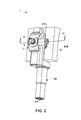
- FIG. 2 is a perspective view of a holder for a concave holographic grating according to the invention
- FIG. 3 is a cross-sectional view of the holder according to FIG. 2 along the line A-A and
- FIG. 4 is a cross-sectional view of the holder according to FIG. 2 along the line B-B.
- reference 17 denotes a flash lamp, e.g. a xenon flash lamp, the light flashes of which via a condenser and a block filter 18 and an entrance port 15 impinges on a concave holographic grating 2 .
- the grating 2 is used for impinging monochromatic light of various wave-lengths onto an output port 20 coupled to an optical fiber 21 .
- the grating 2 causes a diffraction of the light and thus different and desired wave-lengths of light can be directed towards the port 20 by revolving the grating around a pivot point P.
- the monochromatic light from the output port 20 is via the optical fiber 21 directed through a flow cell 22 for the liquid to be analyzed to a sample detector 16 as well as to a reference detector 14 so as to make possible to measure the absorbance of light in the flow cell.
- a sample detector 16 as well as to a reference detector 14 so as to make possible to measure the absorbance of light in the flow cell.
- the grating 2 is correctly positioned with a very high accuracy vis-a-vis the entrance slit 8 and the output port 20 .
- the vertex of the concave grating has to be located at the center of rotation.
- FIGS. 2 , 3 and 4 where FIG. 2 is a perspective view of an embodiment of a grating holder according to the invention, FIG. 3 is a cross-sectional view of the holder according to FIG. 2 along the line A-A and FIG. 4 is a cross-sectional view of the holder according to FIG. 2 along the line B-B, reference 1 denotes a grating holder which can be revolved around a revolution axis when choosing different wave-lengths for the optical unit.
- the revolution axis is defined by a shaft 30 , arranged to be rotatably attached to a chassis or the like of the monochromator.
- a grating 2 is solidly attached to a grating hinge 10 having a spherical surface and being tiltable in a seat of the grating holder.
- the spherical surface of the hinge is kept in contact with the seat by means of a grating hinge spring 7 and a locking washer 3 .
- the grating is solidly attached to the grating hinge 10 by means of e.g. gluing and the spherical surface is shaped so as to have its center point located at the vertex of the holographic grating. Hence the position of the vertex of the holographic grating will be kept essentially static with respect to the revolution axis when the grating hinge is adjusted.
- the grating hinge spring 7 is resting on a cylindrical surface having its center axis running through the vertex of the holographic grating.
- the grating hinge 10 comprises a cylindrical section 31 extending from the spherical surface through the holder main body 33 and which comprises a lock groove 32 receiving the locking washer 3 .
- the holder main body 33 comprises a hinge seat 34 and is formed with a through hole 35 for receiving the cylindrical section 31 of the grating hinge 10 .
- the through hole 35 is essentially coaxial with the hinge seat 34 , but as can be seen in FIGS.
- the grating hinge 10 is arranged to enable rotational adjustment of the grating position with respect to the holder 1 , the center point of the rotational adjustment being located at the vertex of the grating 2 .
- the distal end of the cylindrical section 31 is provided with an adjustment head 13 for rotational adjustment of the grating hinge 10 to align the grooved grating lines with the revolution axis of the grating holder 1 , so as to achieve a maximum light yield.
- the upon rotational adjustment by turning the adjustment head 13 the grating hinge 10 is prevented from displacement in the B-B plane my the side walls of the through hole 35 , and in the A-A plane by the adjustment sleeve 6 and the reverse sleeve 9 .
- any adjustments about either axis can be made independent of the other.
- the grating hinge 10 When all settings are made the grating hinge 10 is locked in position by means of a locking screw 12 operating on a locking sleeve 11 that acts on the cylindrical section 31 in the B-B plane in order to avoid disturbance of the adjusted position.
- the locking screw has a conical shape at the tip so as to insert its hit at the center. By doing so any rotation of the grating is prevented when setting the screw.
Landscapes
- Physics & Mathematics (AREA)
- Spectroscopy & Molecular Physics (AREA)
- General Physics & Mathematics (AREA)
- Optics & Photonics (AREA)
- Diffracting Gratings Or Hologram Optical Elements (AREA)
- Investigating Or Analysing Materials By Optical Means (AREA)
Abstract
Description
Claims (4)
Applications Claiming Priority (4)
| Application Number | Priority Date | Filing Date | Title |
|---|---|---|---|
| SE0900417 | 2009-03-30 | ||
| SE0900417-7 | 2009-03-30 | ||
| SE0900417 | 2009-03-30 | ||
| PCT/SE2010/050342 WO2010114466A1 (en) | 2009-03-30 | 2010-03-29 | Holder for a holographic grating |
Publications (2)
| Publication Number | Publication Date |
|---|---|
| US20120013963A1 US20120013963A1 (en) | 2012-01-19 |
| US8857779B2 true US8857779B2 (en) | 2014-10-14 |
Family
ID=42828549
Family Applications (1)
| Application Number | Title | Priority Date | Filing Date |
|---|---|---|---|
| US13/262,251 Active 2031-01-30 US8857779B2 (en) | 2009-03-30 | 2010-03-29 | Holder for a holographic grating |
Country Status (4)
| Country | Link |
|---|---|
| US (1) | US8857779B2 (en) |
| EP (1) | EP2415235A1 (en) |
| JP (1) | JP2012522277A (en) |
| WO (1) | WO2010114466A1 (en) |
Cited By (2)
| Publication number | Priority date | Publication date | Assignee | Title |
|---|---|---|---|---|
| US20140218793A1 (en) * | 2011-09-06 | 2014-08-07 | Illinois Tool Works Inc. | Apparatus for microscopic detection of hardness |
| US10717161B2 (en) * | 2015-11-04 | 2020-07-21 | Fanuc Corporation | Rotating axis supporting device |
Citations (35)
| Publication number | Priority date | Publication date | Assignee | Title |
|---|---|---|---|---|
| US973558A (en) * | 1909-04-12 | 1910-10-25 | Edwin F Pierce | Adjustable joint for electric-light fixtures. |
| US4496416A (en) | 1982-03-31 | 1985-01-29 | Carl-Zeiss-Stiftung | Method and apparatus for adjusting and mounting optical components in optical instruments |
| US4668059A (en) * | 1984-08-24 | 1987-05-26 | Toyota Jidosha Kabushiki Kaisha | Rear view mirror assembly |
| JPH02119633A (en) | 1988-10-28 | 1990-05-07 | Suzuki Motor Co Ltd | Control device for diesel engine with supercharger |
| US5124857A (en) * | 1991-04-29 | 1992-06-23 | Pitz Francis G | Vehicular light monitoring apparatus |
| JPH0634860A (en) | 1992-07-21 | 1994-02-10 | Mitsubishi Electric Corp | Optical component holding mechanism |
| JPH07103823A (en) | 1993-10-01 | 1995-04-21 | Fuji Xerox Co Ltd | Multiplex spectrometer and measuring method |
| US5436769A (en) * | 1991-12-21 | 1995-07-25 | Britax Rainsfords Pty. Limited | Rear view mirror assembly for motor vehicle |
| JPH07199038A (en) | 1994-01-10 | 1995-08-04 | Sumitomo Heavy Ind Ltd | Flapping adjusting device for concave mirror |
| US5604589A (en) | 1995-02-14 | 1997-02-18 | Hewlett-Packard Company | Diode array spectrophotometer |
| EP0984253A2 (en) | 1998-09-03 | 2000-03-08 | Foss NIRSystems, Inc. | Spectroscopic instrument with offset grating |
| JP2000167683A (en) | 1998-12-03 | 2000-06-20 | Mitsubishi Electric Corp | Optical path adjusting device with reflecting mirror |
| US6226084B1 (en) | 1996-02-27 | 2001-05-01 | Amersham Pharmacia Biotech Ab | Calibration method |
| WO2001059488A1 (en) | 2000-02-11 | 2001-08-16 | Pietro Sgarbi | Process for obtaining biquadratic optical surfaces and in particular schmidt correctors |
| US20040227049A1 (en) * | 2001-12-21 | 2004-11-18 | Lang-Mekra North America, Llc | Linkage arrangement for the adjustment of rearview mirrors |
| US6888920B2 (en) * | 2002-09-03 | 2005-05-03 | Basil Eric Blank | Low-cost, high precision goniometric stage for x-ray diffractography |
| US6915996B2 (en) * | 2003-12-11 | 2005-07-12 | Chin-Chih Lin | Pivotal shaft assembly for plane displays |
| US20050151040A1 (en) * | 2004-01-12 | 2005-07-14 | Hsu Feng L. | Adjustable attachment device for attaching an object to a tubular member |
| US20050243390A1 (en) * | 2003-02-24 | 2005-11-03 | Edita Tejnil | Extreme ultraviolet radiation imaging |
| US20060082771A1 (en) | 2004-10-14 | 2006-04-20 | Agilent Technologies, Inc. | Mount of optical components |
| US7110194B2 (en) * | 2002-11-27 | 2006-09-19 | Hubbs Machine & Manufacturing Inc. | Spherical retro-reflector mount negative |
| US7175292B2 (en) * | 2001-08-06 | 2007-02-13 | Schefenacker Vision Systems Australia Pty Ltd | Hand adjustable vehicle mirror mechanism |
| US20070177282A1 (en) * | 2006-01-24 | 2007-08-02 | Canon Kabushiki Kaisha | Holding device and exposure apparatus using the same |
| US7372625B2 (en) * | 2004-10-18 | 2008-05-13 | Leica Microsystems Cms Gmbh | Device for retaining optical components |
| US7495849B2 (en) * | 2006-01-20 | 2009-02-24 | Newport Corporation | Kinematic optical mount |
| US20090196597A1 (en) * | 2008-01-31 | 2009-08-06 | Gioia Messinger | Mounting and Positioning System |
| US7748669B2 (en) * | 2006-12-14 | 2010-07-06 | Kinpo Electronics, Inc. | Adjustable holding frame |
| US20100193649A1 (en) * | 2009-02-02 | 2010-08-05 | Garmin Ltd. | Mount for an electronic device |
| US7916408B2 (en) * | 2008-10-30 | 2011-03-29 | Corning Incorporated | X-Y adjustable optical mount |
| US20110147548A1 (en) * | 2008-09-05 | 2011-06-23 | Kang Pil-Sik | Ball head for camera tripod capable of finely adjusting front and rear angles through mechanical manipulation |
| US8061920B2 (en) * | 2006-11-29 | 2011-11-22 | Wimberley, Inc. | Pivoting ball mount having four equally spaced contact points |
| US8083190B1 (en) * | 2010-09-07 | 2011-12-27 | Giga-Byte Technology Co., Ltd | Angular adjustment mechanism |
| US8282055B2 (en) * | 2007-10-30 | 2012-10-09 | Flm Gmbh Foto-, Licht- Und Messtechnisches Zubehoer | Tripod head |
| US20130078855A1 (en) * | 2011-08-25 | 2013-03-28 | Iomounts Llc | Apparatus and methods for supporting an article |
| US8451552B2 (en) * | 2008-01-17 | 2013-05-28 | Canon Kabushiki Kaisha | Lens driving device |
Family Cites Families (1)
| Publication number | Priority date | Publication date | Assignee | Title |
|---|---|---|---|---|
| JPH02119633U (en) * | 1989-03-10 | 1990-09-26 |
-
2010
- 2010-03-29 JP JP2012503368A patent/JP2012522277A/en active Pending
- 2010-03-29 US US13/262,251 patent/US8857779B2/en active Active
- 2010-03-29 WO PCT/SE2010/050342 patent/WO2010114466A1/en not_active Ceased
- 2010-03-29 EP EP10759121A patent/EP2415235A1/en not_active Withdrawn
Patent Citations (35)
| Publication number | Priority date | Publication date | Assignee | Title |
|---|---|---|---|---|
| US973558A (en) * | 1909-04-12 | 1910-10-25 | Edwin F Pierce | Adjustable joint for electric-light fixtures. |
| US4496416A (en) | 1982-03-31 | 1985-01-29 | Carl-Zeiss-Stiftung | Method and apparatus for adjusting and mounting optical components in optical instruments |
| US4668059A (en) * | 1984-08-24 | 1987-05-26 | Toyota Jidosha Kabushiki Kaisha | Rear view mirror assembly |
| JPH02119633A (en) | 1988-10-28 | 1990-05-07 | Suzuki Motor Co Ltd | Control device for diesel engine with supercharger |
| US5124857A (en) * | 1991-04-29 | 1992-06-23 | Pitz Francis G | Vehicular light monitoring apparatus |
| US5436769A (en) * | 1991-12-21 | 1995-07-25 | Britax Rainsfords Pty. Limited | Rear view mirror assembly for motor vehicle |
| JPH0634860A (en) | 1992-07-21 | 1994-02-10 | Mitsubishi Electric Corp | Optical component holding mechanism |
| JPH07103823A (en) | 1993-10-01 | 1995-04-21 | Fuji Xerox Co Ltd | Multiplex spectrometer and measuring method |
| JPH07199038A (en) | 1994-01-10 | 1995-08-04 | Sumitomo Heavy Ind Ltd | Flapping adjusting device for concave mirror |
| US5604589A (en) | 1995-02-14 | 1997-02-18 | Hewlett-Packard Company | Diode array spectrophotometer |
| US6226084B1 (en) | 1996-02-27 | 2001-05-01 | Amersham Pharmacia Biotech Ab | Calibration method |
| EP0984253A2 (en) | 1998-09-03 | 2000-03-08 | Foss NIRSystems, Inc. | Spectroscopic instrument with offset grating |
| JP2000167683A (en) | 1998-12-03 | 2000-06-20 | Mitsubishi Electric Corp | Optical path adjusting device with reflecting mirror |
| WO2001059488A1 (en) | 2000-02-11 | 2001-08-16 | Pietro Sgarbi | Process for obtaining biquadratic optical surfaces and in particular schmidt correctors |
| US7175292B2 (en) * | 2001-08-06 | 2007-02-13 | Schefenacker Vision Systems Australia Pty Ltd | Hand adjustable vehicle mirror mechanism |
| US20040227049A1 (en) * | 2001-12-21 | 2004-11-18 | Lang-Mekra North America, Llc | Linkage arrangement for the adjustment of rearview mirrors |
| US6888920B2 (en) * | 2002-09-03 | 2005-05-03 | Basil Eric Blank | Low-cost, high precision goniometric stage for x-ray diffractography |
| US7110194B2 (en) * | 2002-11-27 | 2006-09-19 | Hubbs Machine & Manufacturing Inc. | Spherical retro-reflector mount negative |
| US20050243390A1 (en) * | 2003-02-24 | 2005-11-03 | Edita Tejnil | Extreme ultraviolet radiation imaging |
| US6915996B2 (en) * | 2003-12-11 | 2005-07-12 | Chin-Chih Lin | Pivotal shaft assembly for plane displays |
| US20050151040A1 (en) * | 2004-01-12 | 2005-07-14 | Hsu Feng L. | Adjustable attachment device for attaching an object to a tubular member |
| US20060082771A1 (en) | 2004-10-14 | 2006-04-20 | Agilent Technologies, Inc. | Mount of optical components |
| US7372625B2 (en) * | 2004-10-18 | 2008-05-13 | Leica Microsystems Cms Gmbh | Device for retaining optical components |
| US7495849B2 (en) * | 2006-01-20 | 2009-02-24 | Newport Corporation | Kinematic optical mount |
| US20070177282A1 (en) * | 2006-01-24 | 2007-08-02 | Canon Kabushiki Kaisha | Holding device and exposure apparatus using the same |
| US8061920B2 (en) * | 2006-11-29 | 2011-11-22 | Wimberley, Inc. | Pivoting ball mount having four equally spaced contact points |
| US7748669B2 (en) * | 2006-12-14 | 2010-07-06 | Kinpo Electronics, Inc. | Adjustable holding frame |
| US8282055B2 (en) * | 2007-10-30 | 2012-10-09 | Flm Gmbh Foto-, Licht- Und Messtechnisches Zubehoer | Tripod head |
| US8451552B2 (en) * | 2008-01-17 | 2013-05-28 | Canon Kabushiki Kaisha | Lens driving device |
| US20090196597A1 (en) * | 2008-01-31 | 2009-08-06 | Gioia Messinger | Mounting and Positioning System |
| US20110147548A1 (en) * | 2008-09-05 | 2011-06-23 | Kang Pil-Sik | Ball head for camera tripod capable of finely adjusting front and rear angles through mechanical manipulation |
| US7916408B2 (en) * | 2008-10-30 | 2011-03-29 | Corning Incorporated | X-Y adjustable optical mount |
| US20100193649A1 (en) * | 2009-02-02 | 2010-08-05 | Garmin Ltd. | Mount for an electronic device |
| US8083190B1 (en) * | 2010-09-07 | 2011-12-27 | Giga-Byte Technology Co., Ltd | Angular adjustment mechanism |
| US20130078855A1 (en) * | 2011-08-25 | 2013-03-28 | Iomounts Llc | Apparatus and methods for supporting an article |
Non-Patent Citations (1)
| Title |
|---|
| Notice of Preliminary Rejection Dated Feb. 25, 2014 Issued on Corresponding JP Application No. 2012-503368. |
Cited By (3)
| Publication number | Priority date | Publication date | Assignee | Title |
|---|---|---|---|---|
| US20140218793A1 (en) * | 2011-09-06 | 2014-08-07 | Illinois Tool Works Inc. | Apparatus for microscopic detection of hardness |
| US9496099B2 (en) * | 2011-09-06 | 2016-11-15 | Illinois Tool Works Inc. | Apparatus for microscopic detection of hardness |
| US10717161B2 (en) * | 2015-11-04 | 2020-07-21 | Fanuc Corporation | Rotating axis supporting device |
Also Published As
| Publication number | Publication date |
|---|---|
| US20120013963A1 (en) | 2012-01-19 |
| JP2012522277A (en) | 2012-09-20 |
| WO2010114466A1 (en) | 2010-10-07 |
| EP2415235A1 (en) | 2012-02-08 |
Similar Documents
| Publication | Publication Date | Title |
|---|---|---|
| US8482652B2 (en) | Imaging devices with components for reflecting optical data and associated methods of use and manufacture | |
| JP2017510327A (en) | Rotating prism, prism mount configuration, and endoscope with variable viewing direction | |
| US8857779B2 (en) | Holder for a holographic grating | |
| JP2007121324A (en) | X-ray diffractometer | |
| JP5786477B2 (en) | Photometer | |
| USRE40870E1 (en) | Adjusting element device | |
| US4597643A (en) | Pivotable filter holder for microscopes | |
| US20080013086A1 (en) | Confocal spectrometer with astigmatic aperturing | |
| US4281928A (en) | Optical transit square with focusable crossing telescopes | |
| US20030223111A1 (en) | Sample analysis device having a eucentric goniometer and associated method | |
| CN201837457U (en) | Spectrophotometer with grating adjusting structure | |
| JP2000088648A (en) | Spectroscopic analyzer | |
| US7224460B2 (en) | Mapping-measurement apparatus | |
| DE102010015641B4 (en) | spectrometer | |
| CN105928878B (en) | Device for spherical surface crystal spectrometer centering | |
| US12436094B2 (en) | Adjustable optical system for a spectrograph | |
| CN115268001B (en) | Incident light beam adjusting mechanism applicable to off-axis integrating cavity | |
| CN219320094U (en) | Portable microscopic Raman device | |
| CN205749245U (en) | Sphere crystal spectrometer centralising device | |
| EP0128053B1 (en) | Tool for measuring the azimuth angle of an antenna | |
| JP3182646B2 (en) | Right-angle collimating level and level adapter | |
| CN222719418U (en) | Adjustable carrier for spectrometer | |
| JPH07159157A (en) | Lightwave rangefinder | |
| JP6020641B2 (en) | Photometer | |
| JP3896413B2 (en) | Spectroscopic element mounting mechanism |
Legal Events
| Date | Code | Title | Description |
|---|---|---|---|
| AS | Assignment |
Owner name: GE HEALTHCARE BIO-SCIENCES AB, SWEDEN Free format text: ASSIGNMENT OF ASSIGNORS INTEREST;ASSIGNORS:HORNQVIST, MIKAEL;AKERSTROM, PATRIK;TORMOD, STIG;SIGNING DATES FROM 20100901 TO 20100903;REEL/FRAME:026995/0289 |
|
| STCF | Information on status: patent grant |
Free format text: PATENTED CASE |
|
| MAFP | Maintenance fee payment |
Free format text: PAYMENT OF MAINTENANCE FEE, 4TH YEAR, LARGE ENTITY (ORIGINAL EVENT CODE: M1551) Year of fee payment: 4 |
|
| AS | Assignment |
Owner name: CYTIVA SWEDEN AB, SWEDEN Free format text: CHANGE OF NAME;ASSIGNOR:GE HEALTHCARE BIO-SCIENCES AB;REEL/FRAME:054262/0184 Effective date: 20200612 |
|
| MAFP | Maintenance fee payment |
Free format text: PAYMENT OF MAINTENANCE FEE, 8TH YEAR, LARGE ENTITY (ORIGINAL EVENT CODE: M1552); ENTITY STATUS OF PATENT OWNER: LARGE ENTITY Year of fee payment: 8 |
|
| MAFP | Maintenance fee payment |
Free format text: PAYMENT OF MAINTENANCE FEE, 12TH YEAR, LARGE ENTITY (ORIGINAL EVENT CODE: M1553); ENTITY STATUS OF PATENT OWNER: LARGE ENTITY Year of fee payment: 12 |