US8857765B2 - Method and apparatus for attaching an aircraft fuselage frame to a wing box - Google Patents
Method and apparatus for attaching an aircraft fuselage frame to a wing box Download PDFInfo
- Publication number
- US8857765B2 US8857765B2 US13/652,975 US201213652975A US8857765B2 US 8857765 B2 US8857765 B2 US 8857765B2 US 201213652975 A US201213652975 A US 201213652975A US 8857765 B2 US8857765 B2 US 8857765B2
- Authority
- US
- United States
- Prior art keywords
- wing box
- attachment
- aircraft body
- aircraft
- wing
- Prior art date
- Legal status (The legal status is an assumption and is not a legal conclusion. Google has not performed a legal analysis and makes no representation as to the accuracy of the status listed.)
- Active, expires
Links
Images


Classifications
-
- B—PERFORMING OPERATIONS; TRANSPORTING
- B64—AIRCRAFT; AVIATION; COSMONAUTICS
- B64C—AEROPLANES; HELICOPTERS
- B64C1/00—Fuselages; Constructional features common to fuselages, wings, stabilising surfaces or the like
- B64C1/26—Attaching the wing or tail units or stabilising surfaces
-
- Y—GENERAL TAGGING OF NEW TECHNOLOGICAL DEVELOPMENTS; GENERAL TAGGING OF CROSS-SECTIONAL TECHNOLOGIES SPANNING OVER SEVERAL SECTIONS OF THE IPC; TECHNICAL SUBJECTS COVERED BY FORMER USPC CROSS-REFERENCE ART COLLECTIONS [XRACs] AND DIGESTS
- Y10—TECHNICAL SUBJECTS COVERED BY FORMER USPC
- Y10T—TECHNICAL SUBJECTS COVERED BY FORMER US CLASSIFICATION
- Y10T29/00—Metal working
- Y10T29/49—Method of mechanical manufacture
- Y10T29/49616—Structural member making
- Y10T29/49622—Vehicular structural member making
Definitions
- the following disclosure relates generally to aircraft structures and, more particularly, to aircraft wing-to-body attachments.
- a significant portion of aircraft final assembly time is spent in joining the wing assembly to the aircraft body.
- Conventional wing-to-body installation attaches frame stub beams used to splice the outboard wing box to the center wing box as well as to a vertical flange connecting the aircraft body skin to the wing box.
- the interface to the wing box includes both body stub beams and the wing box stringer details and fasteners.
- the aircraft body side panel frames are split in two to allow a lower frame segment to deflect relative to the wing to body integration position. This configuration results in added frame weight due to the aircraft body frame splice.
- the secondary fuel barrier application process contains hazardous fumes, and cannot be fully completed until after this installation is complete. This places an expensive and complex process in the wing to body integration location.
- An aircraft disclosed herein includes an aircraft body having a fuselage skin on an outboard member of the aircraft body, a wing box extending through a member of the aircraft body, where the wing box being enclosed and capable of being pressurized. At least one pair of an attachment member and an attachment link member is fixedly attached to an outer surface of the wing box and the fuselage skin.
- An attachment apparatus for an aircraft disclosed herein includes an aircraft body having a plurality of body frame members on an outboard member of the aircraft body and a wing box extending through a member of the aircraft body.
- the attachment apparatus includes at least one pair of an attachment member and an attachment link member fixedly attached to an outer surface of the wing box.
- the attachment member includes an upwardly extending projection that receives the outboard member of the aircraft body, a downwardly extending member that receives the outboard member of the surface of the center wing box, and an inboard extending projection that receives the attachment link member being connected to an inboard outer surface of the wing box.
- a plurality of fasteners fixedly attached the aircraft body to the attachment member and attachment link member, thereby securing the aircraft body to the wing box.
- a method of assembling an aircraft disclosed herein includes constructing a wing box, constructing an aircraft body to be connected to the wing box, attaching at least one attachment member to at least one of an outer surface of the wing box or an outboard member of the aircraft body, aligning the aircraft body for fixed attachment to the wing box, and fastening the aircraft body to the wing box with fasteners via the at least one attachment member.
- FIG. 1 is a top isometric view of an aircraft having a wing member joined to an aircraft body in accordance with an embodiment disclosed herein;
- FIG. 2 is a partially cutaway isometric view illustrating a first embodiment of a one-piece attachment member joined to a wing box and a fuselage;
- FIG. 3 is a partially cutaway forward or rearward view illustrating the first embodiment of the one-piece attachment member of FIG. 2 joined to a wing box and a fuselage;
- FIG. 4 is a partially cutaway isometric view illustrating a second embodiment of a two-piece attachment member joined to a wing box and a fuselage;
- FIG. 5 is a partially cutaway forward or rearward view illustrating a second embodiment of the two-piece attachment member of FIG. 4 joined to a wing box and a fuselage;
- FIG. 6 is an exploded isometric view illustrating a second embodiment of the two-piece attachment member of FIGS. 4-5 in a process of being joined to a wing box and a fuselage;
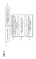
- FIG. 7 is a logical flowchart process illustrating a method of attaching a wing assembly to an aircraft body
- FIG. 8 is a logical flowchart process illustrating a method of loading an aircraft body in a grounded position and an airborne position.
- an aircraft wing may be attached to an aircraft body by fasteners that allow the aircraft body to be attached to the wing assembly without any fastening devices penetrating the wing assembly.
- fasteners that allow the aircraft body to be attached to the wing assembly without any fastening devices penetrating the wing assembly.
- FIG. 1 is a top isometric view of an aircraft 1 having a wing assembly 2 attached to an aircraft body 3 in accordance with an embodiment presented herein.
- the aircraft body 3 includes a right aircraft body member 3 R and a corresponding left aircraft body member 3 L.
- the wing assembly 2 includes a right wing assembly member 2 R extending outwardly from the right aircraft body member 3 R, and a left wing assembly member 2 L extending outwardly from the left aircraft body member 3 L.
- the wing assembly 2 further includes a wing box 10 extending through at least a member of the aircraft body 3 .
- the wing box 10 structurally attaches the right wing assembly member 2 R to the left wing assembly member 2 L.
- Wing assembly members 2 R and 2 L are joined to the aircraft body members 3 R and 3 L, respectively, at an adjoining intersection 5 , where an outer wing skin 6 of the wing assembly 2 intersects an outer body skin 7 of the aircraft body 3 .
- the wing box 10 may be completely located within the wing assembly 2 and may further define an interior cavity structure, (not shown), that may include a fuel cell or any other cavity that may be separate compartmentalized and independent from the aircraft body 3 .
- the interior cavity structure defined by the wing box 10 may be pressure tested independently from body 3 pressure testing. This allows testing for any pressure leakage before any aircraft body structure 3 is attached to the wing assembly 2 .
- the wing box further includes a forward and rearward facing surfaces that are disposed in vertical direction
- the embodiments presented herein are novel methods and systems for adjoining the aircraft body 3 to the wing assembly 2 via the wing box 10 by means of attachment members 20 disposed on forward and rearward lateral edges of the wing box 10 , proximate where the outer body skin 7 meets the outer wing skin 6 .
- the aircraft 1 is a commercial aircraft having a first engine 4 R carried by the right wing assembly member 2 R, and a second engine 4 L carried by the left wing assembly member 2 L.
- the methods and systems described herein for attaching wings to bodies can be used on other aircraft, includes other commercial and non-commercial aircraft.
- other transport aircraft having one or more engines mounted to the aircraft body.
- FIG. 2 is a partially cutaway isometric view and FIG. 3 is a forward or rearward cutaway view illustrating a first embodiment of a one-piece attachment member 30 joined to a partially illustrated corner section of a wing box 10 and a fuselage structure 50 .
- Wing box 10 is partially illustrated to identify an upper surface 12 of the wing box 10 and either a forward facing or rearward facing outer vertical surface 14 of the wing box 10 . This orientation is based on whether the one-piece attachment member 30 is disposed on either the forward facing section of the wing box 10 , or on the rearward facing section of the wing box 10 , as both are illustrated in FIG. 1 .
- the one-piece attachment member 30 is additionally located on the outboard member of the wing box 10 to enable fixed attachment to the aircraft body 3 via a fuselage member 50 that may including both a fuselage skin 52 and a trapezoid panel 54 .
- a vertical load on the fuselage member 50 may be reduced when used in conjunction with the trapezoid panel 54 .
- the fuselage skin 52 may also encompass the outboard member of the trapezoid panel 54 , (not illustrated).
- the one-piece attachment member 30 includes an upper extension 32 that is fixedly connected via fasteners 33 to the fuselage member 50 , particularly to the fuselage skin 52 , and an inboard extension 34 having a distal end 36 opposite the fuselage member 50 being connected via an extension link 60 to a vertical member 14 of the wing box 10 via a wing box fitting 70 . Additionally, the one-piece attachment member 30 includes a lower extension 38 that is fixedly connected via fasteners 39 to the vertical member 14 of the wing box 10 , and either the trapezoid member 54 or directly to an outboard member of the fuselage skin 52 , (not illustrated).
- the inboard extension 34 is oriented a distance D above a plane defined by the upper surface 12 of the wing box 10 .
- a bending moment M increases the resistance or stiffness to any bending moment from any transient or static loading due to the distal end 36 of the inboard extension 34 having a substantial longitudinal separation from the attachment planes of the upper 32 and lower 38 extensions connected to their respective fuselage 52 and wing box 10 /trapezoid member 54 fastening locations.
- the inboard distance X of the distal end 36 of the inboard extension 34 to the centerline of bending moment M is greater than the width W, (see FIG. 3 ), of the upper 32 and lower 38 extension to accomplish this stiffening feature.
- FIG. 4 is a partially cutaway isometric view and FIG. 5 is a forward or rearward cutaway view illustrating a second embodiment of a two-piece attachment member 40 joined to a partially illustrated corner section of a wing box 10 and a fuselage structure 50 . Similar elements between the various embodiments presented herein will be identified with similar reference numbers.
- Wing box 10 is partially illustrated to identify an upper surface 12 of the wing box 10 and either a forward or rearward vertical surface 14 of the wing box 10 .
- the two-piece attachment member 40 is similarly located on the outboard member of the wing box 10 to enable fixed attachment to the aircraft body 3 via a fuselage member 50 that may including a fuselage skin 52 .
- the two-piece attachment member 40 includes an upper extension 42 that is fixedly connected via fasteners 43 to the fuselage member 50 , particularly to the fuselage skin 52 , and an inboard extension 44 having a distal end 46 opposite the fuselage member 50 being connected via an extension link 60 to a vertical member 14 of the wing box 10 via a wing box fitting 70 . Additionally, the two-piece attachment member 40 includes a separate lower extension 48 that is fixedly connected via fasteners 49 to the trapezoid member 54 , and to the vertical member 14 of the wing box 10 . The upper extension 42 and the lower extension 48 are fixedly connected via fasteners 41 .
- the inboard extension 44 is oriented a distance D above a plane defined by the upper surface 12 of the wing box 10 .
- a bending moment M increases the resistance or stiffness to any bending moment from any transient or static loading due to the distal end 46 of the inboard extension 44 having a substantial longitudinal separation from the attachment planes of the upper 42 and lower 48 extensions connected to each other and to their respective fuselage 52 and wing box 10 /trapezoid member 54 fastening locations.
- the inboard distance X of the distal end 46 of the inboard extension 44 to the centerline of the bending moment M is greater than the width W, (see FIG. 5 ), of the upper 42 and lower 48 extension to accomplish this stiffening feature.
- FIG. 6 illustrates an exploded isometric view of the second embodiment of the two-piece attachment member of FIGS. 4-5 in a method of being joined to a wing box 10 and a fuselage member 50 .
- the method attaches the upper extension 42 /inboard extension 44 members to the fuselage member 50 , particularly the fuselage skin 52 , via fasteners 43 .
- Attachment link 60 may be attached to the distal end 46 of the inboard extension 44 at this time, or may be attached to the wing box fitting 70 , (not shown), in the alternative.
- the method attaches the lower extension 48 to the wing trapezoid member 54 , and the vertical member 14 of the wing box 10 via fasteners 49 .
- any internal cavity in the wing box 10 may be pressure tested to determine its structural integrity.
- the first assembly including the upper extension 42 /inboard extension 44 members and the attached fuselage member 50 are then positioned into alignment with the corresponding second assembly including the lower extension 48 and wing box 10 .
- the first and second assembly are then brought into contact at a connecting bottom member of the upper extension 42 and a connecting top member of the lower extension 48 and fixedly connected with fasteners 41 .
- the attachment link 60 then may be connected between the distal end 46 of the inboard extension 44 and the wing box fitting 70 mounted on the wing box 10 .
- any secondary fuel barrier application process on any external parts of a fuel cell located within the wing box 10 common to the body pressure boundary may be completed in a controlled environment prior to the wing assembly 2 is joined to the aircraft body 3 and will not be penetrated during the wing to body joining
- the wing assembly 2 carries the majority of the forces through the fuselage 50 to the aircraft body 3 via the attachment members ( 30 or 40 ) and the link 60 attachment wing box fitting 70 .
- a first loading condition is present when the aircraft 1 is on the ground, having no lift component on the wing assembly 2 , where the attachment members ( 30 or 40 ) bear the weight of the aircraft body 3 and transfer it through the wing assembly 2 to main landing gears (not illustrated).
- a second loading condition is present where the attachment members ( 30 or 40 ) transfer a lift load induced by the in-flight wing assembly 2 to the aircraft body 3 via the attachment members ( 30 or 40 ) and the link 60 attachment wing box fitting 70 .
- FIG. 7 is a logical flowchart process illustrating a method of attaching a wing assembly to an aircraft body as shown in FIG. 6 .
- the method starts with constructing 100 a wing box 10 , and constructing 102 the aircraft body 3 to be connected to the wing box 10 .
- An attachment member 30 , 40 is attached 104 to either an outer surface 14 of the wing box 10 or an outboard member 52 of the fuselage member 50 .
- the attachment member may include a one-piece design 30 that is attached to either the wing box 10 or the fuselage member 50 , or may include a two-piece design 40 where each respective piece connects to the wing box 10 and the fuselage member 50 and is later joined together.
- the fuselage member 50 is aligned 106 with the wing box 10 such that the attachment member is either connected to the respective surface of the opposing fuselage member 50 or wing box 10 in the one-piece design 30 , or in the two-piece design 40 , the upper 42 and lower 48 attachment members are connected together. Additionally, in either the one-piece or two-piece configuration, the attachment link 60 on the inboard extension is aligned with the wing box fitting 70 . Finally, the fuselage member 50 is fastened 108 to the wing box 10 with a plurality of fasteners such that the attachment member fixedly holds the fuselage member 50 to the wing box 10 .
- FIG. 8 is a logical flowchart process illustrating a method of loading an aircraft body in a grounded position and an airborne position. Similar to the method described in FIG. 7 , a wing box 10 is constructed 200 , and an aircraft body 3 is constructed 202 to be connected to the wing box 10 . An attachment member 30 , 40 is attached 204 to either an outer surface 14 of the wing box 10 or an outboard member 52 of the fuselage member 50 . As mentioned above, the attachment member may include a one-piece design 30 that is attached to either the wing box 10 or the fuselage member 50 , or may include a two-piece design 40 where each respective piece connects to the wing box 10 and the fuselage member 50 and is later joined together.
- the fuselage member 50 is aligned 206 with the wing box 10 such that the attachment member is either connected to the respective surface of the opposing fuselage member 50 or wing box 10 in the one-piece design 30 , or in the two-piece design 40 , the upper 42 and lower 48 attachment members are connected together via fasteners 41 . Additionally, in either the one-piece or two-piece configuration, the attachment link 60 on the inboard extension is aligned with wing box fitting 70 .
- the fuselage member 50 is fastened 208 to the wing box 10 with a plurality of fasteners such that the attachment member fixedly holds the fuselage member 50 to the wing box 10 .
- the method further includes a first loading condition 210 when the aircraft 1 is on the ground, with no lift component on the wing assembly 2 , where the attachment members 30 , 40 bear the weight of the aircraft body 3 and transfer it through the wing assembly 2 and wing box 10 to main landing gears (not shown).
- a second loading condition 212 is present where the attachment members ( 30 , 40 ) transfer a lift load induced by the in-flight wing assembly 2 to the aircraft body 3 and fuselage member 50 from the wing assembly 2 through the wing box 10 .
- Aircraft body support members 30 , 40 may be fully installed to either the fuselage 50 or the wing box 10 in one-piece embodiment, or separately installed in a two-piece embodiment on the fuselage 50 and the wing box 10 for subsequent attachment.
- the embodiments disclosed herein allow the aircraft body frame 3 connection to the forward or rearward vertical surface 14 of the wing box 10 to be de-coupled from a common interface of a wing assembly 3 with the wing fuel cell in the wing box 10 by only attaching the aircraft body frame attachment members 30 , 40 to the wing assembly 2 wing box 10 through vertical attachment interfaces 32 , 38 and 42 , 48 outside the wing box 10 .
- This configuration allows the wing box 10 to be completed prior to joining to the aircraft body 3 . It also allows the aircraft body frames to be fully installed to the aircraft body skin 52 in one piece prior to joining to the wing 2 , thereby reducing weight and eliminating frame splicing of multiple frame parts. This configuration results in a weight savings and less manufacturing work at the wing to body join position by significantly reducing the difficult installation of body frame stub beams to the wing box.
Landscapes
- Engineering & Computer Science (AREA)
- Mechanical Engineering (AREA)
- Aviation & Aerospace Engineering (AREA)
- Connection Of Plates (AREA)
- Toys (AREA)
- Automatic Assembly (AREA)
Priority Applications (5)
| Application Number | Priority Date | Filing Date | Title |
|---|---|---|---|
| US13/652,975 US8857765B2 (en) | 2012-10-16 | 2012-10-16 | Method and apparatus for attaching an aircraft fuselage frame to a wing box |
| JP2015536842A JP6159409B2 (ja) | 2012-10-16 | 2013-10-08 | 航空機胴体フレームをウィングボックスに取り付ける方法及び装置 |
| CN201380044940.4A CN104603007B (zh) | 2012-10-16 | 2013-10-08 | 用于将航空器机身框架附接到翼盒的方法和设备 |
| EP13779498.8A EP2909085B1 (en) | 2012-10-16 | 2013-10-08 | Method and apparatus for attaching an aircraft fuselage frame to a wing box |
| PCT/US2013/063913 WO2014062423A1 (en) | 2012-10-16 | 2013-10-08 | Method and apparatus for attaching an aircraft fuselage frame to a wing box |
Applications Claiming Priority (1)
| Application Number | Priority Date | Filing Date | Title |
|---|---|---|---|
| US13/652,975 US8857765B2 (en) | 2012-10-16 | 2012-10-16 | Method and apparatus for attaching an aircraft fuselage frame to a wing box |
Publications (2)
| Publication Number | Publication Date |
|---|---|
| US20140103162A1 US20140103162A1 (en) | 2014-04-17 |
| US8857765B2 true US8857765B2 (en) | 2014-10-14 |
Family
ID=49385426
Family Applications (1)
| Application Number | Title | Priority Date | Filing Date |
|---|---|---|---|
| US13/652,975 Active 2033-06-24 US8857765B2 (en) | 2012-10-16 | 2012-10-16 | Method and apparatus for attaching an aircraft fuselage frame to a wing box |
Country Status (5)
| Country | Link |
|---|---|
| US (1) | US8857765B2 (cg-RX-API-DMAC7.html) |
| EP (1) | EP2909085B1 (cg-RX-API-DMAC7.html) |
| JP (1) | JP6159409B2 (cg-RX-API-DMAC7.html) |
| CN (1) | CN104603007B (cg-RX-API-DMAC7.html) |
| WO (1) | WO2014062423A1 (cg-RX-API-DMAC7.html) |
Cited By (7)
| Publication number | Priority date | Publication date | Assignee | Title |
|---|---|---|---|---|
| DE102017117314A1 (de) * | 2017-07-31 | 2019-01-31 | Airbus Operations Gmbh | Befestigungseinheit zum beweglichen Befestigen einer Luftfahrzeugkomponente an einer Tragstruktur eines Luftfahrzeugs |
| US10712730B2 (en) | 2018-10-04 | 2020-07-14 | The Boeing Company | Methods of synchronizing manufacturing of a shimless assembly |
| US11136107B2 (en) * | 2018-10-05 | 2021-10-05 | The Boeing Company | Method and apparatus for attaching a fuselage frame to a wing box |
| US11174042B2 (en) | 2018-10-09 | 2021-11-16 | The Boeing Company | Wing join system and method for a wing assembly |
| US11188688B2 (en) | 2015-11-06 | 2021-11-30 | The Boeing Company | Advanced automated process for the wing-to-body join of an aircraft with predictive surface scanning |
| US20220135202A1 (en) * | 2020-11-03 | 2022-05-05 | The Boeing Company | System and method for securing a longeron to a wing and fuselage of an aircraft |
| US12330767B2 (en) * | 2023-04-04 | 2025-06-17 | Hyundai Motor Company | Wing load support structure of the fuselage |
Families Citing this family (4)
| Publication number | Priority date | Publication date | Assignee | Title |
|---|---|---|---|---|
| FR2998868B1 (fr) * | 2012-11-30 | 2016-02-05 | Airbus Operations Sas | Dispositif de fixation intermediaire entre un fuselage d'aeronef et un train d'atterrissage d'aeronef |
| US9828083B2 (en) | 2014-11-14 | 2017-11-28 | The Boeing Company | Methods and components for wing-to-fuselage integration |
| US10106240B2 (en) | 2015-07-13 | 2018-10-23 | The Boeing Company | Pinned fuselage-to-wing connection |
| CN109774964A (zh) * | 2019-01-28 | 2019-05-21 | 陕西智翔航空科技发展有限公司 | 复合材料机身对合型架 |
Citations (41)
| Publication number | Priority date | Publication date | Assignee | Title |
|---|---|---|---|---|
| US1865964A (en) | 1926-09-27 | 1932-07-05 | Rohrbach Patents Corp | Monoplane |
| US2001260A (en) | 1932-07-20 | 1935-05-14 | Martin James | Construction and arrangement of aeroplane wings |
| US2211089A (en) * | 1938-03-29 | 1940-08-13 | Curtiss Wright Corp | Wing and fuselage construction |
| US2370801A (en) | 1941-05-14 | 1945-03-06 | Cons Vultee Aireraft Corp | Airplane wing structure |
| US2412778A (en) | 1944-12-18 | 1946-12-17 | Cons Vultee Aircraft Corp | Suspension type flooring for aircraft |
| US2749061A (en) | 1954-06-18 | 1956-06-05 | Wesley A Franz | Airplane wing stress compensating structure assembly |
| US2779558A (en) | 1952-04-09 | 1957-01-29 | Sncase | Fuselage of aerodynes |
| US3018985A (en) | 1956-12-31 | 1962-01-30 | Martin Marietta Corp | Swept wing with unswept spar |
| US4390153A (en) | 1979-08-11 | 1983-06-28 | Messerschmitt-Boelkow-Blohm Gesellschaft Mit Beschraenkter Haftung | Apparatus for securing a wing to the body of a craft |
| US4417708A (en) | 1982-05-12 | 1983-11-29 | Grumman Aerospace Corporation | Interchangeable wing aircraft |
| US4893964A (en) * | 1989-02-06 | 1990-01-16 | Grumman Aerospace Corporation | Interlocking structural members utilizing overlying composite strips |
| US6808143B2 (en) * | 1996-03-22 | 2004-10-26 | The Boeing Company | Determinant wing assembly |
| US6843450B2 (en) * | 2002-10-21 | 2005-01-18 | The Boeing Company | Method and apparatus for rotatably supporting movable components, including canards |
| US20060018710A1 (en) * | 2004-07-22 | 2006-01-26 | Jean-Marc Durand | Device for joining composite structure elements with metallic structure elements |
| US20070095982A1 (en) * | 2005-10-31 | 2007-05-03 | The Boeing Company | Single piece fuselage barrel |
| WO2008105805A2 (en) | 2006-09-15 | 2008-09-04 | The Boeing Company | Trapezoidal panel pin joint allowing free deflection between fuselage and wing |
| US20080283666A1 (en) * | 2007-04-04 | 2008-11-20 | Grieve James C | Method and apparatus for attaching a wing to a body |
| US7501814B2 (en) * | 2006-09-07 | 2009-03-10 | Southwest Research Institute | Apparatus and method for second-layer through-bushing inspection of aircraft wing attachment fittings using electric current perturbation |
| US20090065644A1 (en) * | 2005-03-23 | 2009-03-12 | Airbus France | Device and method for non-symmetrical mixed carbon-metal assembly |
| US20090146007A1 (en) * | 2007-12-05 | 2009-06-11 | The Boeing Company | Methods and Systems for Attaching Aircraft Wings to Fuselages |
| US20090283637A1 (en) * | 2007-03-07 | 2009-11-19 | Airbus France | Aircraft floor and fuselage supplied with said floor |
| US7721992B2 (en) * | 2007-03-07 | 2010-05-25 | The Boeing Company | Aircraft floor to fuselage attachment |
| US20100200691A1 (en) * | 2007-04-17 | 2010-08-12 | Airbus France | Device for attaching a lift member to the fuselage of an aircraft |
| US7909290B2 (en) * | 2005-12-20 | 2011-03-22 | Airbus Operations Limited | Joint for use in aircraft construction |
| US20110089292A1 (en) | 2009-01-26 | 2011-04-21 | Airbus Operations Limited | Aircraft joint |
| US20110147521A1 (en) * | 2009-07-16 | 2011-06-23 | Airbus Operations (S.A.S.) | Method of constructing a fixed-wing aircraft |
| US7975965B2 (en) * | 2008-05-13 | 2011-07-12 | The Boeing Company | Wing tip joint in airfoils |
| US8061655B1 (en) * | 2009-03-25 | 2011-11-22 | The Boeing Company | Aircraft configuration utilizing fuselage, wing, empennage, and exhaust flow control devices |
| US8142126B2 (en) * | 2005-09-02 | 2012-03-27 | The Boeing Company | Multi-piece fastener with self-indexing nut |
| US8146242B2 (en) * | 2005-11-01 | 2012-04-03 | The Boeing Company | Methods and systems for manufacturing a family of aircraft wings and other composite structures |
| FR2970463A1 (fr) | 2011-01-17 | 2012-07-20 | Airbus Operations Sas | Dispositif d'eclissage a tenue mecanique amelioree. |
| US20120193475A1 (en) * | 2011-01-28 | 2012-08-02 | Airbus Operations (S.A.S.) | Connector for stiffening frames between an aircraft fuselage and a wing box |
| US20120241560A1 (en) * | 2011-03-25 | 2012-09-27 | The Boeing Company | Joint Sealing System |
| US8286911B2 (en) * | 2008-02-29 | 2012-10-16 | Airbus Operations Limited | Fitting for pivotally connecting aerodynamic control element to aircraft structure |
| US20120286091A1 (en) * | 2010-08-26 | 2012-11-15 | The Boeing Company | Composite Aircraft Joint |
| US20120286090A1 (en) * | 2011-03-25 | 2012-11-15 | Airbus Operations (Societe Par Actions Simplifiee) | Connection of a fuselage to an aircraft wing |
| US20130020440A1 (en) * | 2010-03-25 | 2013-01-24 | Airbus Operations, S L. | Structure for joining torsion boxes in an aircraft using a triform fitting made from non-metallic composite materials |
| US20130032670A1 (en) * | 2010-03-30 | 2013-02-07 | Airbus Operations Gmbh | Wall component for an aircraft |
| US20130062467A1 (en) * | 2010-01-28 | 2013-03-14 | Airbus Operations Limited | Aircraft wing box joint |
| US8408495B2 (en) * | 2009-04-21 | 2013-04-02 | Airbus Operations, S.L. | Fittings for attaching the vertical tail stabilizer of an aircraft |
| US20130175395A1 (en) * | 2012-01-10 | 2013-07-11 | Gulfstream Aerospace Corporation | Mounting assembly and method for mounting a sound-deadening body to a fuselage of an aircraft |
Family Cites Families (6)
| Publication number | Priority date | Publication date | Assignee | Title |
|---|---|---|---|---|
| US3942746A (en) * | 1971-12-27 | 1976-03-09 | General Dynamics Corporation | Aircraft having improved performance with beaver-tail afterbody configuration |
| US4120998A (en) * | 1977-02-03 | 1978-10-17 | Northrop Corporation | Composite structure |
| US5332178A (en) * | 1992-06-05 | 1994-07-26 | Williams International Corporation | Composite wing and manufacturing process thereof |
| DE102005034891B4 (de) * | 2005-07-26 | 2007-06-14 | Airbus Deutschland Gmbh | Querkraftanschluss |
| DE102006051572B4 (de) * | 2006-11-02 | 2010-01-21 | Airbus Deutschland Gmbh | Flügel-Rumpf-Verbindung eines Flugzeugs |
| CN100577512C (zh) * | 2008-06-24 | 2010-01-06 | 北京航空航天大学 | 一种民用大型飞机机翼机身连接接头 |
-
2012
- 2012-10-16 US US13/652,975 patent/US8857765B2/en active Active
-
2013
- 2013-10-08 JP JP2015536842A patent/JP6159409B2/ja active Active
- 2013-10-08 WO PCT/US2013/063913 patent/WO2014062423A1/en not_active Ceased
- 2013-10-08 CN CN201380044940.4A patent/CN104603007B/zh active Active
- 2013-10-08 EP EP13779498.8A patent/EP2909085B1/en active Active
Patent Citations (47)
| Publication number | Priority date | Publication date | Assignee | Title |
|---|---|---|---|---|
| US1865964A (en) | 1926-09-27 | 1932-07-05 | Rohrbach Patents Corp | Monoplane |
| US2001260A (en) | 1932-07-20 | 1935-05-14 | Martin James | Construction and arrangement of aeroplane wings |
| US2211089A (en) * | 1938-03-29 | 1940-08-13 | Curtiss Wright Corp | Wing and fuselage construction |
| US2370801A (en) | 1941-05-14 | 1945-03-06 | Cons Vultee Aireraft Corp | Airplane wing structure |
| US2412778A (en) | 1944-12-18 | 1946-12-17 | Cons Vultee Aircraft Corp | Suspension type flooring for aircraft |
| US2779558A (en) | 1952-04-09 | 1957-01-29 | Sncase | Fuselage of aerodynes |
| US2749061A (en) | 1954-06-18 | 1956-06-05 | Wesley A Franz | Airplane wing stress compensating structure assembly |
| US3018985A (en) | 1956-12-31 | 1962-01-30 | Martin Marietta Corp | Swept wing with unswept spar |
| US4390153A (en) | 1979-08-11 | 1983-06-28 | Messerschmitt-Boelkow-Blohm Gesellschaft Mit Beschraenkter Haftung | Apparatus for securing a wing to the body of a craft |
| US4417708A (en) | 1982-05-12 | 1983-11-29 | Grumman Aerospace Corporation | Interchangeable wing aircraft |
| US4893964A (en) * | 1989-02-06 | 1990-01-16 | Grumman Aerospace Corporation | Interlocking structural members utilizing overlying composite strips |
| US6808143B2 (en) * | 1996-03-22 | 2004-10-26 | The Boeing Company | Determinant wing assembly |
| US6843450B2 (en) * | 2002-10-21 | 2005-01-18 | The Boeing Company | Method and apparatus for rotatably supporting movable components, including canards |
| US20060018710A1 (en) * | 2004-07-22 | 2006-01-26 | Jean-Marc Durand | Device for joining composite structure elements with metallic structure elements |
| US7195418B2 (en) * | 2004-07-22 | 2007-03-27 | Airbus France | Device for joining composite structure elements with metallic structure elements |
| US20090065644A1 (en) * | 2005-03-23 | 2009-03-12 | Airbus France | Device and method for non-symmetrical mixed carbon-metal assembly |
| US8142126B2 (en) * | 2005-09-02 | 2012-03-27 | The Boeing Company | Multi-piece fastener with self-indexing nut |
| US20070095982A1 (en) * | 2005-10-31 | 2007-05-03 | The Boeing Company | Single piece fuselage barrel |
| US8146242B2 (en) * | 2005-11-01 | 2012-04-03 | The Boeing Company | Methods and systems for manufacturing a family of aircraft wings and other composite structures |
| US7909290B2 (en) * | 2005-12-20 | 2011-03-22 | Airbus Operations Limited | Joint for use in aircraft construction |
| US7501814B2 (en) * | 2006-09-07 | 2009-03-10 | Southwest Research Institute | Apparatus and method for second-layer through-bushing inspection of aircraft wing attachment fittings using electric current perturbation |
| WO2008105805A2 (en) | 2006-09-15 | 2008-09-04 | The Boeing Company | Trapezoidal panel pin joint allowing free deflection between fuselage and wing |
| US7546979B1 (en) * | 2006-09-15 | 2009-06-16 | The Boeing Company | Trapezoidal panel pin joint allowing free deflection between fuselage and wing |
| US7721992B2 (en) * | 2007-03-07 | 2010-05-25 | The Boeing Company | Aircraft floor to fuselage attachment |
| US20090283637A1 (en) * | 2007-03-07 | 2009-11-19 | Airbus France | Aircraft floor and fuselage supplied with said floor |
| US8016236B2 (en) * | 2007-04-04 | 2011-09-13 | The Boeing Company | Method and apparatus for attaching a wing to a body |
| US20080283666A1 (en) * | 2007-04-04 | 2008-11-20 | Grieve James C | Method and apparatus for attaching a wing to a body |
| US20100200691A1 (en) * | 2007-04-17 | 2010-08-12 | Airbus France | Device for attaching a lift member to the fuselage of an aircraft |
| US20090146007A1 (en) * | 2007-12-05 | 2009-06-11 | The Boeing Company | Methods and Systems for Attaching Aircraft Wings to Fuselages |
| US7887009B2 (en) * | 2007-12-05 | 2011-02-15 | The Boeing Company | Methods and systems for attaching aircraft wings to fuselages |
| US8286911B2 (en) * | 2008-02-29 | 2012-10-16 | Airbus Operations Limited | Fitting for pivotally connecting aerodynamic control element to aircraft structure |
| US7975965B2 (en) * | 2008-05-13 | 2011-07-12 | The Boeing Company | Wing tip joint in airfoils |
| US20110089292A1 (en) | 2009-01-26 | 2011-04-21 | Airbus Operations Limited | Aircraft joint |
| US8371532B2 (en) * | 2009-01-26 | 2013-02-12 | Airbus Operations Limited | Aircraft joint |
| US8061655B1 (en) * | 2009-03-25 | 2011-11-22 | The Boeing Company | Aircraft configuration utilizing fuselage, wing, empennage, and exhaust flow control devices |
| US8408495B2 (en) * | 2009-04-21 | 2013-04-02 | Airbus Operations, S.L. | Fittings for attaching the vertical tail stabilizer of an aircraft |
| US20110147521A1 (en) * | 2009-07-16 | 2011-06-23 | Airbus Operations (S.A.S.) | Method of constructing a fixed-wing aircraft |
| US20130062467A1 (en) * | 2010-01-28 | 2013-03-14 | Airbus Operations Limited | Aircraft wing box joint |
| US20130020440A1 (en) * | 2010-03-25 | 2013-01-24 | Airbus Operations, S L. | Structure for joining torsion boxes in an aircraft using a triform fitting made from non-metallic composite materials |
| US8573539B2 (en) * | 2010-03-25 | 2013-11-05 | Airbus Operations, S.L. | Structure for joining torsion boxes in an aircraft using a triform fitting made from non-metallic composite materials |
| US20130032670A1 (en) * | 2010-03-30 | 2013-02-07 | Airbus Operations Gmbh | Wall component for an aircraft |
| US20120286091A1 (en) * | 2010-08-26 | 2012-11-15 | The Boeing Company | Composite Aircraft Joint |
| FR2970463A1 (fr) | 2011-01-17 | 2012-07-20 | Airbus Operations Sas | Dispositif d'eclissage a tenue mecanique amelioree. |
| US20120193475A1 (en) * | 2011-01-28 | 2012-08-02 | Airbus Operations (S.A.S.) | Connector for stiffening frames between an aircraft fuselage and a wing box |
| US20120241560A1 (en) * | 2011-03-25 | 2012-09-27 | The Boeing Company | Joint Sealing System |
| US20120286090A1 (en) * | 2011-03-25 | 2012-11-15 | Airbus Operations (Societe Par Actions Simplifiee) | Connection of a fuselage to an aircraft wing |
| US20130175395A1 (en) * | 2012-01-10 | 2013-07-11 | Gulfstream Aerospace Corporation | Mounting assembly and method for mounting a sound-deadening body to a fuselage of an aircraft |
Non-Patent Citations (3)
| Title |
|---|
| International Search Report from PCT/US2013/063913 mailed Mar. 11, 2014. |
| U.S. Official Action dated Aug. 19, 2013 in U.S. Appl. No. 13/444,441. |
| U.S. Official Action dated Jun. 18, 2014 in U.S. Appl. No. 13/444,441. |
Cited By (11)
| Publication number | Priority date | Publication date | Assignee | Title |
|---|---|---|---|---|
| US11188688B2 (en) | 2015-11-06 | 2021-11-30 | The Boeing Company | Advanced automated process for the wing-to-body join of an aircraft with predictive surface scanning |
| DE102017117314A1 (de) * | 2017-07-31 | 2019-01-31 | Airbus Operations Gmbh | Befestigungseinheit zum beweglichen Befestigen einer Luftfahrzeugkomponente an einer Tragstruktur eines Luftfahrzeugs |
| US11352121B2 (en) | 2017-07-31 | 2022-06-07 | Airbus Operations Gmbh | Fastening unit for movably fastening an aircraft component to a support structure of an aircraft |
| US10712730B2 (en) | 2018-10-04 | 2020-07-14 | The Boeing Company | Methods of synchronizing manufacturing of a shimless assembly |
| US11294357B2 (en) | 2018-10-04 | 2022-04-05 | The Boeing Company | Methods of synchronizing manufacturing of a shimless assembly |
| US11415968B2 (en) | 2018-10-04 | 2022-08-16 | The Boeing Company | Methods of synchronizing manufacturing of a shimless assembly |
| US11136107B2 (en) * | 2018-10-05 | 2021-10-05 | The Boeing Company | Method and apparatus for attaching a fuselage frame to a wing box |
| US11174042B2 (en) | 2018-10-09 | 2021-11-16 | The Boeing Company | Wing join system and method for a wing assembly |
| US20220135202A1 (en) * | 2020-11-03 | 2022-05-05 | The Boeing Company | System and method for securing a longeron to a wing and fuselage of an aircraft |
| US12286210B2 (en) * | 2020-11-03 | 2025-04-29 | The Boeing Company | System and method for securing a structural member to a wing and a fuselage of an aircraft |
| US12330767B2 (en) * | 2023-04-04 | 2025-06-17 | Hyundai Motor Company | Wing load support structure of the fuselage |
Also Published As
| Publication number | Publication date |
|---|---|
| WO2014062423A1 (en) | 2014-04-24 |
| EP2909085B1 (en) | 2018-08-29 |
| CN104603007A (zh) | 2015-05-06 |
| CN104603007B (zh) | 2016-08-10 |
| JP6159409B2 (ja) | 2017-07-05 |
| EP2909085A1 (en) | 2015-08-26 |
| US20140103162A1 (en) | 2014-04-17 |
| JP2015533111A (ja) | 2015-11-19 |
Similar Documents
| Publication | Publication Date | Title |
|---|---|---|
| US8857765B2 (en) | Method and apparatus for attaching an aircraft fuselage frame to a wing box | |
| US7887009B2 (en) | Methods and systems for attaching aircraft wings to fuselages | |
| KR102073995B1 (ko) | 항공기의 복합재료 구조를 연결하기 위한 장치 및 방법 | |
| US20250153841A1 (en) | Aircraft wing-to-fuselage interface permitting positional adjustment | |
| US8740151B1 (en) | Adjustable splice fitting for shimless connection of structual members | |
| US9180956B1 (en) | Methods and apparatus for attaching an aircraft wing assembly to an aircraft body | |
| CN111003141B (zh) | 用于将机身构架附接至机翼翼盒的方法和装置 | |
| US12091155B2 (en) | Structural arrangement for strut-braced wing assembly of an aircraft | |
| US12384517B2 (en) | Aircraft wing unit with pressure fence | |
| EP3619109B1 (en) | Aircraft wing unit with upper wing skin defining pressure floor | |
| EP2626291B1 (en) | Structural joint having continuous skin with inside and outside stringers | |
| EP4365083B1 (en) | SYSTEMS AND METHODS FOR COUPLING A SPACER TO AN AIRCRAFT WING | |
| CN216332703U (zh) | 一种机载分布式sar雷达改装结构 | |
| CN219927958U (zh) | 一种大载荷轻质隐身的复合材料机身结构 | |
| US20260109446A1 (en) | Fuselage frame | |
| CN116729634A (zh) | 多段可分离组合式复合材料航空吊舱 |
Legal Events
| Date | Code | Title | Description |
|---|---|---|---|
| AS | Assignment |
Owner name: THE BOEING COMPANY, ILLINOIS Free format text: ASSIGNMENT OF ASSIGNORS INTEREST;ASSIGNORS:THOMAS, GRANT BRIAN;LIN, CHUN-LIANG;ANDREWS, FRANCIS E.;AND OTHERS;SIGNING DATES FROM 20121010 TO 20121011;REEL/FRAME:029138/0338 |
|
| STCF | Information on status: patent grant |
Free format text: PATENTED CASE |
|
| MAFP | Maintenance fee payment |
Free format text: PAYMENT OF MAINTENANCE FEE, 4TH YEAR, LARGE ENTITY (ORIGINAL EVENT CODE: M1551) Year of fee payment: 4 |
|
| MAFP | Maintenance fee payment |
Free format text: PAYMENT OF MAINTENANCE FEE, 8TH YEAR, LARGE ENTITY (ORIGINAL EVENT CODE: M1552); ENTITY STATUS OF PATENT OWNER: LARGE ENTITY Year of fee payment: 8 |
|
| MAFP | Maintenance fee payment |
Free format text: PAYMENT OF MAINTENANCE FEE, 12TH YEAR, LARGE ENTITY (ORIGINAL EVENT CODE: M1553); ENTITY STATUS OF PATENT OWNER: LARGE ENTITY Year of fee payment: 12 |