US8857581B2 - Dual spring rate damper - Google Patents
Dual spring rate damper Download PDFInfo
- Publication number
- US8857581B2 US8857581B2 US13/461,414 US201213461414A US8857581B2 US 8857581 B2 US8857581 B2 US 8857581B2 US 201213461414 A US201213461414 A US 201213461414A US 8857581 B2 US8857581 B2 US 8857581B2
- Authority
- US
- United States
- Prior art keywords
- blade
- rotor hub
- piston
- fluid
- adjustable damper
- Prior art date
- Legal status (The legal status is an assumption and is not a legal conclusion. Google has not performed a legal analysis and makes no representation as to the accuracy of the status listed.)
- Expired - Lifetime
Links
Images


Classifications
-
- F—MECHANICAL ENGINEERING; LIGHTING; HEATING; WEAPONS; BLASTING
- F16—ENGINEERING ELEMENTS AND UNITS; GENERAL MEASURES FOR PRODUCING AND MAINTAINING EFFECTIVE FUNCTIONING OF MACHINES OR INSTALLATIONS; THERMAL INSULATION IN GENERAL
- F16F—SPRINGS; SHOCK-ABSORBERS; MEANS FOR DAMPING VIBRATION
- F16F13/00—Units comprising springs of the non-fluid type as well as vibration-dampers, shock-absorbers, or fluid springs
- F16F13/04—Units comprising springs of the non-fluid type as well as vibration-dampers, shock-absorbers, or fluid springs comprising both a plastics spring and a damper, e.g. a friction damper
- F16F13/06—Units comprising springs of the non-fluid type as well as vibration-dampers, shock-absorbers, or fluid springs comprising both a plastics spring and a damper, e.g. a friction damper the damper being a fluid damper, e.g. the plastics spring not forming a part of the wall of the fluid chamber of the damper
- F16F13/08—Units comprising springs of the non-fluid type as well as vibration-dampers, shock-absorbers, or fluid springs comprising both a plastics spring and a damper, e.g. a friction damper the damper being a fluid damper, e.g. the plastics spring not forming a part of the wall of the fluid chamber of the damper the plastics spring forming at least a part of the wall of the fluid chamber of the damper
-
- B—PERFORMING OPERATIONS; TRANSPORTING
- B64—AIRCRAFT; AVIATION; COSMONAUTICS
- B64C—AEROPLANES; HELICOPTERS
- B64C27/00—Rotorcraft; Rotors peculiar thereto
- B64C27/32—Rotors
- B64C27/35—Rotors having elastomeric joints
-
- B—PERFORMING OPERATIONS; TRANSPORTING
- B64—AIRCRAFT; AVIATION; COSMONAUTICS
- B64C—AEROPLANES; HELICOPTERS
- B64C27/00—Rotorcraft; Rotors peculiar thereto
- B64C27/32—Rotors
- B64C27/37—Rotors having articulated joints
- B64C27/39—Rotors having articulated joints with individually articulated blades, i.e. with flapping or drag hinges
-
- B—PERFORMING OPERATIONS; TRANSPORTING
- B64—AIRCRAFT; AVIATION; COSMONAUTICS
- B64C—AEROPLANES; HELICOPTERS
- B64C27/00—Rotorcraft; Rotors peculiar thereto
- B64C27/51—Damping of blade movements
-
- F—MECHANICAL ENGINEERING; LIGHTING; HEATING; WEAPONS; BLASTING
- F16—ENGINEERING ELEMENTS AND UNITS; GENERAL MEASURES FOR PRODUCING AND MAINTAINING EFFECTIVE FUNCTIONING OF MACHINES OR INSTALLATIONS; THERMAL INSULATION IN GENERAL
- F16F—SPRINGS; SHOCK-ABSORBERS; MEANS FOR DAMPING VIBRATION
- F16F13/00—Units comprising springs of the non-fluid type as well as vibration-dampers, shock-absorbers, or fluid springs
- F16F13/04—Units comprising springs of the non-fluid type as well as vibration-dampers, shock-absorbers, or fluid springs comprising both a plastics spring and a damper, e.g. a friction damper
- F16F13/06—Units comprising springs of the non-fluid type as well as vibration-dampers, shock-absorbers, or fluid springs comprising both a plastics spring and a damper, e.g. a friction damper the damper being a fluid damper, e.g. the plastics spring not forming a part of the wall of the fluid chamber of the damper
- F16F13/24—Units comprising springs of the non-fluid type as well as vibration-dampers, shock-absorbers, or fluid springs comprising both a plastics spring and a damper, e.g. a friction damper the damper being a fluid damper, e.g. the plastics spring not forming a part of the wall of the fluid chamber of the damper the central part of the unit being supported by one element and both extremities of the unit being supported by a single other element, i.e. double acting mounting
-
- F—MECHANICAL ENGINEERING; LIGHTING; HEATING; WEAPONS; BLASTING
- F16—ENGINEERING ELEMENTS AND UNITS; GENERAL MEASURES FOR PRODUCING AND MAINTAINING EFFECTIVE FUNCTIONING OF MACHINES OR INSTALLATIONS; THERMAL INSULATION IN GENERAL
- F16F—SPRINGS; SHOCK-ABSORBERS; MEANS FOR DAMPING VIBRATION
- F16F13/00—Units comprising springs of the non-fluid type as well as vibration-dampers, shock-absorbers, or fluid springs
- F16F13/04—Units comprising springs of the non-fluid type as well as vibration-dampers, shock-absorbers, or fluid springs comprising both a plastics spring and a damper, e.g. a friction damper
- F16F13/26—Units comprising springs of the non-fluid type as well as vibration-dampers, shock-absorbers, or fluid springs comprising both a plastics spring and a damper, e.g. a friction damper characterised by adjusting or regulating devices responsive to exterior conditions
-
- F—MECHANICAL ENGINEERING; LIGHTING; HEATING; WEAPONS; BLASTING
- F16—ENGINEERING ELEMENTS AND UNITS; GENERAL MEASURES FOR PRODUCING AND MAINTAINING EFFECTIVE FUNCTIONING OF MACHINES OR INSTALLATIONS; THERMAL INSULATION IN GENERAL
- F16F—SPRINGS; SHOCK-ABSORBERS; MEANS FOR DAMPING VIBRATION
- F16F2230/00—Purpose; Design features
- F16F2230/30—Sealing arrangements
Definitions
- the present invention relates in general to the field of rotor hubs for aircraft.
- the present invention relates to a dual spring rate damper for soft in-plane rotor hubs.
- Many aircraft rotors especially those for helicopters and tiltrotor aircraft, include a lead/lag hinge designed to allow in-plane motion of a blade about an axis generally normal to the plane of rotation, such that the blade “runs in” or “gets behind” with respect to other blades. This is mainly to compensate for the extra rotational speed that comes with “blade flapping” and to compensate for differences in blade aerodynamic drag encountered at various moments of one rotational cycle.
- dampers are normally incorporated in the design of this type of rotor system.
- the purpose of the dampers is to absorb the acceleration and deceleration of the rotor blades and maintain the frequency of the lead/lag motion within a desired range.
- the damper is an elastomeric damper.
- the spring rate chosen for a lead/lag damper is a compromise between the value required for the desired in-plane stiffness and a value that reduces load and fatigue on the rotor and other aircraft components.
- FIG. 1 is a perspective view of a four-blade aircraft rotor hub according to the present invention
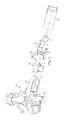
- FIG. 2 is an exploded perspective view of a three-blade aircraft rotor hub according to the invention
- FIG. 3 is a partially sectioned perspective view of the rotor hub of FIG. 2 ;
- FIG. 4 is a cross-sectional plan view of a portion of the rotor hub of FIG. 2 ;
- FIG. 5 is a cross-sectional plan view of a dual-spring-rate damper for use in the rotor hubs of the present invention
- FIG. 6 is a cross-sectional plan view of the damper of FIG. 5 , the damper being configured for a softer spring rate;
- FIG. 7 is a cross-sectional plan view of the damper of FIG. 5 , the damper being configured for a stiffer spring rate.
- hub 11 is configured as a four-blade hub for use as a proprotor hub of a tiltrotor aircraft.
- Rotor hubs according to the invention may have more or fewer blades and may also be configured for use on other rotary-wing aircraft, including helicopters.
- Hub 11 has a central member 13 which is adapted to fixedly receive mast 15 .
- Mast 15 is rotated by torque from a drive unit, which may be routed through a transmission (not shown), and the torque is transferred through mast 15 to central member 13 for rotating hub 11 .
- Blades (not shown) are attached to hub 11 with blade attachment assemblies 17 , each assembly 17 comprising a blade attachment strap 19 and a blade grip 21 .
- Straps 19 are circumferential and oriented vertically to extend out of the plane of rotation. Straps 19 are hingedly connected to central member 13 at flapping hinges 23 , and blade grips 21 are rotatably and pivotally attached to the outer end of straps 19 .
- Flapping hinges 23 allow for out-of-plane flapping motion of each blade about an axis generally parallel to the plane of rotation of hub 11 .
- Blade grips 21 rotate relative to straps 19 about radial pitch axes that are generally parallel to the plane of rotation of hub 11 , and a pitch horn 25 extends from the leading edge of each grip 21 for controlling the pitch of the associated blade.
- Pitch horns 25 combine with the associated flapping hinge 23 to yield the desired delta-3 pitch-flap coupling.
- each blade grip 21 is connected to strap 19 with a lead/lag bearing (not shown), and the grip 21 pivots relative to the associated strap 19 about a lead/lag axis generally normal to the plane of rotation of hub 11 .
- a damper 29 is installed in each strap 19 and is operably connected to the associated blade grip 21 .
- Dampers 29 are each preferably selectively switchable between at least two spring rates, allowing for hub 11 to be readily configured to have selected in-plane stiffness values.
- the advantage of selectable in-plane stiffness is that hub 11 can be made stiff enough to prevent ground-resonance conditions when the aircraft is resting on a surface, yet hub 11 can be made softer during flight for minimizing loads and fatigue on components of hub 11 and other components of the aircraft.
- Dampers 29 are preferably switched through electric actuation, though other types of actuation may alternatively be used, and the switching of dampers 29 is preferably automatically controlled by aircraft control systems.
- the aircraft control systems may switch dampers 29 to a stiffer setting upon a signal that the aircraft is within a selected proximity of the ground or upon a signal generated by sensors indicating contact of the landing gear with the ground.
- FIGS. 2 through 4 show a simplified, three-blade alternative embodiment of a rotor hub of the invention.
- FIG. 2 is an exploded view
- FIG. 3 is a partial cutaway of the assembly
- FIG. 4 is a cross-sectional plan view of the assembly.
- hub 31 includes central member 33 , blade straps 35 , and blade grips 37 .
- Central member 33 is adapted to fixedly receive mast 34 .
- Straps 35 are circumferential and are hingedly connected to central member 33 at flapping hinge 39 . This allows for out-of-plane flapping motion of blades (not shown) attached to blade grips 37 .
- Each blade grip 37 receives the root end of a blade in the outer end of grip 37 , and the inner end of each grip 37 is connected to the outer end of the associated strap 35 with pitch horn brackets 41 .
- Each grip 37 can rotate about an associated pitch axis 43 , and the pitch for the blades is controlled using pitch horns 45 on brackets 41 .
- An elastomeric bearing 47 is received within a recess 49 of each bracket 41 to provide for in-plane, chordwise pivoting of brackets 41 and grips 37 about a lead/lag axis 51 passing through the focus of each bearing 47 .
- Both elastomeric bearing 47 and flapping hinge 39 are located within strap 35 , with the axes for these hinges being non-coincident. This configuration allow for better packaging of the components of hub 31 , especially in tiltrotor applications.
- hubs of the invention may be constructed in any appropriate configuration, including hubs using pins or similar connections for the lead/lag hinge.
- In-plane motion of a blade about the associated lead/lag axis 51 causes a proportional in-plane motion of post 53 .
- post 53 is located inward of axis 51 , the in-plane motion of post 53 is in the direction opposite the movement of the blade.
- This motion causes displacement of piston 65 along axis 67 , which is resisted by the bulging and/or shearing deflection of elastomeric seals 69 , 71 .
- Each damper 59 is selectively switchable between at least two spring rates, including while hub 31 is in use, allowing hub 31 to be switched between at least two values of in-plane stiffness.
- Damper 59 is one example of a switchable, multi-spring-rate damper according to the present invention that can be used in hubs of the present invention, though other types of selectively switchable, multiple-spring-rate dampers may be used.
- a more detailed view of damper 59 is shown in FIGS. 5 through 7 and described below.
- damper 59 is shown in a cross-sectional plan view
- Elastomeric seals 69 , 71 are fixedly mounted to inner surface 73 of housing 75 and fixedly mounted to outer surface 77 of piston 65 .
- Seals 69 , 71 are preferably formed as “sandwich” structures, with alternating layers of an elastomeric material 79 and a rigid, non-elastomeric material 81 , such as a metal. This type of structure is nearly incompressible in a direction generally normal to the layers, but the structure allows for a limited amount of shearing motion.
- Each seal 69 , 71 sealingly engages inner surface 73 and outer surface 77 to form fluid chambers 83 , 85 within housing 75 .
- Each fluid chamber 83 , 85 is adjacent an end of piston 65 and contains a preferably incompressible fluid, such as a hydraulic fluid or an oil. The fluid may flow between chambers 83 , 85 through passages 87 , 89 , 91 , 93 formed in piston 65 and extending from one end of piston 65 to the other end of piston 65 .
- a bore 95 is located on outer surface 77 for receiving inner end 57 of post 53 , which extends from elastomeric bearing 47 ( FIG. 2 ).
- Primary damping passage 87 has valve means, such as rotary valve 97 , for controlling the flow of fluid through primary passage 87 .
- valve passage 99 of valve 97 can be aligned with primary passage 87 for allowing fluid to freely flow between chambers 83 , 85 through primary passage 87 .
- Valve 97 can be rotated between this “open” and a “closed” position, in which valve passage 99 is rotated out of alignment with primary passage 87 , preventing fluid from flowing through passage 87 .
- a secondary passage 89 which is preferably smaller in cross-sectional area than passage 87 , extends through piston 65 for communicating chambers 83 , 85 .
- Secondary passage 89 does not have valve means, so fluid is allowed to flow between chambers 83 , 85 at all times through secondary passage 89 .
- Bypass passages 91 , 93 also extend through piston 65 and communicate chambers 83 , 85 .
- Each bypass passage 91 , 93 has a one-way, spring-biased check valve, items 101 and 103 , respectively, for allowing fluid flow through bypass passages 91 , 93 only when an overpressure occurs in one of chambers 83 , 85 .
- An overpressure in a chamber 83 , 85 will overcome the force of the spring in the opposing check valve 101 , 103 , forcing valve 101 , 103 from a seated position in bypass passage 91 , 93 . Fluid then flows through bypass passage 91 , 93 until the overpressure subsides enough to allow bypass valve 101 , 103 to seat, stopping the flow of fluid.
- FIGS. 6 and 7 illustrate damper 59 in operation.
- damper 59 is shown reacting to a movement of post 53 in the direction shown by arrow 105 when damper is switched to the softer of the two available spring rates.
- Rotary valve 97 is in the open position, in which valve passage 99 is aligned with passage 87 , and this allows fluid to flow between fluid chambers 83 , 85 through passage 87 . Fluid can also flow between chambers 83 , 85 through passage 89 .
- movement of post 53 causes piston 65 to move relative to housing 75 and toward chamber 85 , as is shown in the figure, the movement is resisted by the shear force required to deflect seals 69 , 71 , which are fixedly attached to housing 75 and to piston 65 .
- the shear force provides a spring rate, k shear , for damper 59 .
- the end of piston 65 adjacent chamber 85 applies pressure to the fluid in chamber 85 , forcing the fluid to pass through passages 87 , 89 , which act as a fluid restriction for damping oscillations of piston 65 .
- damper 59 is shown reacting to a movement of post 53 in the direction shown by arrow 105 when damper is switched to the stiffer of the two available spring rates.
- Rotary valve 97 is in the closed position, in which valve passage 99 is out of alignment with passage 87 , and this prevents fluid flow between fluid chambers 83 , 85 through passage 87 . Fluid can flow between chambers 83 , 85 through passage 89 .
- Dampers of the invention may have one piston, such as damper 59 ( FIG. 4 ), or may have more than one piston, such as damper 29 ( FIG. 1 ). Dampers 29 , 59 preferably have a stroke of approximately +/ ⁇ 1.00 in., though dampers 29 , 59 may be constructed in any appropriate size for the particular application. Dampers of the invention are shown as having passages extending through the piston, though passages routed through the damper housing may alternatively be used.
- the damper of the invention has several advantages, including: (1) providing selectively switchable spring rates for lead/lag damping; (2) providing a small, lightweight switchable damper for use in the rotor hubs of the invention; and (3) providing a method of preventing ground resonance conditions while minimizing loads and fatigue on aircraft components.
Landscapes
- Engineering & Computer Science (AREA)
- General Engineering & Computer Science (AREA)
- Mechanical Engineering (AREA)
- Aviation & Aerospace Engineering (AREA)
- Fluid-Damping Devices (AREA)
- Vibration Dampers (AREA)
- Pivots And Pivotal Connections (AREA)
- Hydraulic Turbines (AREA)
- Structures Of Non-Positive Displacement Pumps (AREA)
Abstract
Description
Claims (14)
Priority Applications (1)
| Application Number | Priority Date | Filing Date | Title |
|---|---|---|---|
| US13/461,414 US8857581B2 (en) | 2003-08-27 | 2012-05-01 | Dual spring rate damper |
Applications Claiming Priority (4)
| Application Number | Priority Date | Filing Date | Title |
|---|---|---|---|
| US49807303P | 2003-08-27 | 2003-08-27 | |
| PCT/US2004/027964 WO2005021990A2 (en) | 2003-08-27 | 2004-08-27 | Dual spring rate damper |
| US56817006A | 2006-11-13 | 2006-11-13 | |
| US13/461,414 US8857581B2 (en) | 2003-08-27 | 2012-05-01 | Dual spring rate damper |
Related Parent Applications (3)
| Application Number | Title | Priority Date | Filing Date |
|---|---|---|---|
| US10/568,170 Continuation US8181755B2 (en) | 2003-08-27 | 2004-08-27 | Dual spring rate damper |
| PCT/US2004/027964 Continuation WO2005021990A2 (en) | 2003-08-27 | 2004-08-27 | Dual spring rate damper |
| US56817006A Continuation | 2003-08-27 | 2006-11-13 |
Publications (2)
| Publication Number | Publication Date |
|---|---|
| US20120230823A1 US20120230823A1 (en) | 2012-09-13 |
| US8857581B2 true US8857581B2 (en) | 2014-10-14 |
Family
ID=34272633
Family Applications (3)
| Application Number | Title | Priority Date | Filing Date |
|---|---|---|---|
| US10/567,886 Expired - Lifetime US7828525B2 (en) | 2003-08-27 | 2004-08-27 | Soft in-plane tiltrotor hub |
| US10/568,170 Expired - Fee Related US8181755B2 (en) | 2003-08-27 | 2004-08-27 | Dual spring rate damper |
| US13/461,414 Expired - Lifetime US8857581B2 (en) | 2003-08-27 | 2012-05-01 | Dual spring rate damper |
Family Applications Before (2)
| Application Number | Title | Priority Date | Filing Date |
|---|---|---|---|
| US10/567,886 Expired - Lifetime US7828525B2 (en) | 2003-08-27 | 2004-08-27 | Soft in-plane tiltrotor hub |
| US10/568,170 Expired - Fee Related US8181755B2 (en) | 2003-08-27 | 2004-08-27 | Dual spring rate damper |
Country Status (7)
| Country | Link |
|---|---|
| US (3) | US7828525B2 (en) |
| EP (2) | EP1658184B1 (en) |
| CN (3) | CN102182787A (en) |
| BR (2) | BRPI0413123A (en) |
| CA (2) | CA2533523C (en) |
| DE (2) | DE04819036T1 (en) |
| WO (2) | WO2005021990A2 (en) |
Cited By (4)
| Publication number | Priority date | Publication date | Assignee | Title |
|---|---|---|---|---|
| US20140271182A1 (en) * | 2013-03-14 | 2014-09-18 | Bell Helicopter Textron Inc. | Soft in-plane and stiff out-of-plane rotor system |
| WO2021030630A2 (en) | 2019-08-14 | 2021-02-18 | Unmanned Aerospace Llc | Aerial vehicle |
| US11142307B2 (en) | 2016-10-14 | 2021-10-12 | Airbus Helicopters | Lead-lag damper integrated inside a blade of a rotor |
| US11697492B2 (en) | 2020-04-09 | 2023-07-11 | Roller Bearing Company Of America, Inc. | Rotor blade lead-lag hydraulic damper with centrifugal force compensating damping characteristics |
Families Citing this family (41)
| Publication number | Priority date | Publication date | Assignee | Title |
|---|---|---|---|---|
| CN102182787A (en) * | 2003-08-27 | 2011-09-14 | 贝尔直升机泰克斯特龙公司 | Dual spring rate damper |
| ITTO20070442A1 (en) * | 2007-06-20 | 2008-12-21 | Santino Pancotti | ROTOR FOR A HELICOPTER INCLUDING A VIBRATION DAMPING DEVICE AND ITS REQUALIFICATION METHOD |
| US8548648B2 (en) * | 2007-07-02 | 2013-10-01 | Sikorsky Aircraft Corporation | Fly-by-wire flight control system with electronic lead/lag damper algorithm |
| EP2240366B1 (en) * | 2008-02-12 | 2014-06-18 | Bell Helicopter Textron Inc. | Lead-lag damper for rotor hubs |
| CA2746048C (en) * | 2008-12-18 | 2014-07-08 | Bell Helicopter Textron Inc. | Method and apparatus for improved vibration isolation |
| FR2961172B1 (en) * | 2010-06-14 | 2012-07-27 | Snecma | SUSPENSION OF A TURBOMOTOR OR THE LIKE TO AN AIRCRAFT PYLON WITH INTEGRATED SAFETY. |
| CN101954970B (en) * | 2010-09-09 | 2013-04-03 | 西北工业大学 | Ventilating propeller hub of propeller tip jet helicopter |
| CN103380311B (en) * | 2011-02-24 | 2016-01-20 | 贝尔直升机泰克斯特龙公司 | A kind of hot adaptive damping device and there is the aircraft of this hot adaptive damping device |
| EP2686239B1 (en) * | 2011-06-29 | 2015-08-12 | Bell Helicopter Textron Inc. | Rotor hub for use with high-inertia blades |
| DE102011079144B4 (en) * | 2011-07-14 | 2013-02-07 | Zf Friedrichshafen Ag | Adjustable damper valve device with an emergency operation valve |
| US9327832B2 (en) | 2011-10-03 | 2016-05-03 | Bell Helicopter Textron Inc. | Elastomeric bearing with tapered shims |
| US8662442B2 (en) * | 2011-11-01 | 2014-03-04 | Textron Innovations Inc. | Active prop rotor stability system |
| US9126680B2 (en) | 2011-11-16 | 2015-09-08 | Textron Innovations Inc. | Dual mode rotor hub assembly |
| KR101286232B1 (en) | 2011-11-21 | 2013-07-15 | 한국항공우주산업 주식회사 | Articulated rotor blade hub assembly by single damper |
| US9169010B2 (en) * | 2012-02-24 | 2015-10-27 | Bell Helicopter Textron Inc. | Offset stacked yoke hub for tiltrotor aircraft |
| US9352830B2 (en) | 2012-04-25 | 2016-05-31 | Textron Innovations Inc. | Aircraft rotor with discrete flap hinge |
| US9334048B2 (en) * | 2013-09-18 | 2016-05-10 | Bell Helicopter Textron Inc. | Elastomeric bearing having tapered layers |
| FR3017855B1 (en) * | 2014-02-21 | 2016-04-29 | Airbus Helicopters | ROTOR FOR GIRAVION COMPRISING A MECHANISM OF STOPPING IN BEAT, AND GIRAVION |
| US9555881B2 (en) | 2014-04-02 | 2017-01-31 | The Boeing Company | Propeller/rotor control apparatus and method |
| CN104973241A (en) * | 2015-07-08 | 2015-10-14 | 芜湖万户航空航天科技有限公司 | Unmanned aerial vehicle with main and auxiliary multi-rotor structure |
| US20180103744A1 (en) * | 2015-07-13 | 2018-04-19 | Yolonda Moore | Hanging Curling Iron Holder |
| CN105129083B (en) * | 2015-08-20 | 2019-01-29 | 珠海磐磊智能科技有限公司 | Rotor, paddle folder and aircraft |
| CN105351437B (en) * | 2015-12-15 | 2017-06-30 | 东北大学 | Automatically adjust the intelligent vibration isolator system and method for testing vibration of rigidity and damping |
| CN105972151B (en) * | 2016-07-20 | 2018-03-13 | 芜湖万户航空航天科技有限公司 | Pass through the main shaft and main rotor of the shimmy damping connection of block rubber |
| CN106275422B (en) * | 2016-09-08 | 2018-08-28 | 南京航空航天大学 | A kind of variable speed rigid rotor aircraft propeller hub |
| US10518867B2 (en) | 2016-12-12 | 2019-12-31 | Textron Innovations Inc. | Loop yoke for proprotor systems |
| US10518868B2 (en) * | 2016-12-12 | 2019-12-31 | Textron Innovations Inc. | Soft-in-plane proprotor systems |
| US10793254B2 (en) | 2016-12-12 | 2020-10-06 | Textron Innovations Inc. | Soft-in-plane proprotor systems |
| US20180162526A1 (en) * | 2016-12-12 | 2018-06-14 | Bell Helicopter Textron Inc. | Proprotor Systems for Tiltrotor Aircraft |
| CN108791708B (en) * | 2017-04-27 | 2020-02-18 | 中国船舶重工集团公司第七一九研究所 | Double-acting type pressure spring damper |
| US10457380B2 (en) * | 2017-06-28 | 2019-10-29 | Bell Textron Inc. | Articulated rotor systems with pitch independent damping |
| CN108108527B (en) * | 2017-11-30 | 2020-12-01 | 中国航空工业集团公司沈阳飞机设计研究所 | Theoretical calculation method for vertical stiffness ratio of aircraft landing gear |
| US11027834B2 (en) * | 2018-02-22 | 2021-06-08 | Textron Innovations Inc. | Inboard centrifugal force bearing attachment |
| FR3079577B1 (en) * | 2018-03-30 | 2020-03-13 | Airbus Helicopters | HYDRO ELASTIC SHOCK ABSORBER AND AIRCRAFT |
| US10597150B2 (en) | 2018-04-24 | 2020-03-24 | Textron Innovations Inc. | Articulated rotor systems with blade-to-blade damping |
| US10960969B2 (en) | 2018-10-24 | 2021-03-30 | Bell Helicopter Textron Inc. | Method of improving a stability speed of a tiltrotor aircraft |
| CN109552599A (en) * | 2018-11-06 | 2019-04-02 | 珠海隆华直升机科技有限公司 | Helicopter tail rotor displacement blade assembly and helicopter |
| US10875636B2 (en) * | 2018-11-20 | 2020-12-29 | Textron Innovations Inc. | Variable-pitch ringed rotors for aircraft |
| US11724802B1 (en) | 2020-06-15 | 2023-08-15 | Avx Aircraft Company | Lightweight rotor conversion systems for tiltrotor aircraft |
| US11674397B2 (en) * | 2020-11-18 | 2023-06-13 | General Electric Company | Variable stiffness damper system |
| US12060148B2 (en) | 2022-08-16 | 2024-08-13 | Honeywell International Inc. | Ground resonance detection and warning system and method |
Citations (20)
| Publication number | Priority date | Publication date | Assignee | Title |
|---|---|---|---|---|
| US2155427A (en) * | 1936-10-19 | 1939-04-25 | Autogiro Co Of America | Aircraft sustaining rotor |
| US2603435A (en) | 1948-02-06 | 1952-07-15 | Earl G Metzler | Resilient mounting for airplane wings |
| US2754937A (en) * | 1945-09-25 | 1956-07-17 | United Aircraft Corp | Damper for rotary wing aircraft |
| US2774553A (en) | 1955-04-04 | 1956-12-18 | United Aircraft Corp | Damper by-pass for lag-lead control of helicopter rotor blades |
| US3207457A (en) | 1962-11-06 | 1965-09-21 | Adrijan V Kisovec | Convertiplane |
| US3265167A (en) * | 1964-07-10 | 1966-08-09 | Goodyear Tire & Rubber | Integral molded piston and lining for brakes and method for forming thereof |
| US3303887A (en) | 1964-01-16 | 1967-02-14 | Bolkow Gmbh | Helicopter rotor construction |
| US4135856A (en) * | 1977-02-03 | 1979-01-23 | Lord Corporation | Rotor blade retention system |
| US4273303A (en) | 1979-03-16 | 1981-06-16 | The Boeing Company | Adaptive airplane landing gear |
| US4543040A (en) * | 1982-09-30 | 1985-09-24 | The Boeing Company | Helicopter rotor system |
| US4733854A (en) | 1983-06-10 | 1988-03-29 | Honda Giken Kogyo Kabushiki Kaisha | Fluid sealed mounting |
| US4811919A (en) | 1987-08-06 | 1989-03-14 | Lord Corporation | Volume compensated fluid mount |
| US4947700A (en) | 1988-05-03 | 1990-08-14 | Borg-Warner Automotive, Inc. | Continuously variable transmission system and long travel torsion damper therefor |
| US5374039A (en) | 1992-08-24 | 1994-12-20 | Lord Corporation | Fluid-and-elastomer support device |
| US5439082A (en) | 1994-04-01 | 1995-08-08 | Bell Helicopter Textron Inc. | Hydraulic inertial vibration isolator |
| US5535861A (en) | 1995-06-08 | 1996-07-16 | Lord Corporation | Dual-rate linear damper |
| US5788372A (en) | 1996-05-10 | 1998-08-04 | Lord Corporation | Method and apparatus for reducing transient motion between an aircraft power member and structure during takeoff, landing and maneuvers |
| US6224019B1 (en) | 1998-01-26 | 2001-05-01 | Simula, Inc. | Parachute landing velocity attenuator |
| US20060162778A1 (en) | 2003-08-25 | 2006-07-27 | Nichols Randall W | Drain valve |
| US7828525B2 (en) * | 2003-08-27 | 2010-11-09 | Bell Helicopter Textron Inc. | Soft in-plane tiltrotor hub |
Family Cites Families (19)
| Publication number | Priority date | Publication date | Assignee | Title |
|---|---|---|---|---|
| GB713352A (en) | 1951-03-30 | 1954-08-11 | United Aircraft Corp | Improvements in or relating to rotary wing aircraft |
| GB781356A (en) | 1954-10-01 | 1957-08-21 | United Aircraft Corp | Improvements in or relating to helicopters |
| GB871267A (en) | 1959-06-19 | 1961-06-21 | Kaman Aircraft Corp | Helicopter rotor correction mechanism |
| US3292712A (en) | 1965-04-29 | 1966-12-20 | Lord Corp | Rotor head |
| US3501250A (en) | 1968-03-22 | 1970-03-17 | Boeing Co | Rotor hub |
| FR2063969B1 (en) | 1969-10-16 | 1974-05-24 | Aerospatiale | |
| US3759632A (en) | 1972-07-05 | 1973-09-18 | United Aircraft Corp | Articulated helicopter rotor |
| US3759631A (en) | 1972-07-05 | 1973-09-18 | United Aircraft Corp | Compound bearing for connecting a helicopter blade to a helicopter rotor |
| US3761199A (en) | 1972-07-14 | 1973-09-25 | United Aircraft Corp | Helicopter rotor with redundant load carrying capability |
| US3899991A (en) * | 1973-12-17 | 1975-08-19 | Us Navy | Weather resistant segmented fairing for a tow cable |
| GB1500007A (en) | 1974-08-22 | 1978-02-08 | Westland Aircraft Ltd | Rotor for rotary wing aircraft |
| GB1514347A (en) | 1976-03-05 | 1978-06-14 | Westland Aircraft Ltd | Helicopter rotors |
| US4244677A (en) * | 1978-07-12 | 1981-01-13 | United Technologies Corporation | Cross-beam helicopter rotor with readily replaceable snubber |
| CA1206383A (en) * | 1983-01-18 | 1986-06-24 | Fathom Oceanology Limited | Fairing assembly for towed underwater cables |
| JPH0469423A (en) * | 1990-07-09 | 1992-03-04 | Toyota Motor Corp | Damping force variable shock absorber |
| US5662046A (en) * | 1993-12-14 | 1997-09-02 | Hansen Inc. | Method and apparatus for controlling railway truck hunting and a railway car body supported thereby |
| US5775677A (en) * | 1995-02-07 | 1998-07-07 | Englund; Arlo C. | Air or gas sprung and dampened shock absorber |
| US6644445B2 (en) * | 2001-11-19 | 2003-11-11 | Tenneco Automotive Operating Company Inc. | Floating port blocker |
| US6668986B2 (en) * | 2002-01-08 | 2003-12-30 | Delphi Technologies, Inc. | Active hydraulic fluid vehicular suspension damper |
-
2004
- 2004-08-27 CN CN 201110122132 patent/CN102182787A/en active Pending
- 2004-08-27 DE DE04819036T patent/DE04819036T1/en active Pending
- 2004-08-27 US US10/567,886 patent/US7828525B2/en not_active Expired - Lifetime
- 2004-08-27 CN CNB2004800246504A patent/CN100420608C/en not_active Expired - Fee Related
- 2004-08-27 WO PCT/US2004/027964 patent/WO2005021990A2/en not_active Ceased
- 2004-08-27 US US10/568,170 patent/US8181755B2/en not_active Expired - Fee Related
- 2004-08-27 BR BRPI0413123-1A patent/BRPI0413123A/en not_active Application Discontinuation
- 2004-08-27 EP EP04786599.3A patent/EP1658184B1/en not_active Expired - Lifetime
- 2004-08-27 DE DE04786599T patent/DE04786599T1/en active Pending
- 2004-08-27 EP EP04819036A patent/EP1658222B1/en not_active Expired - Lifetime
- 2004-08-27 CA CA2533523A patent/CA2533523C/en not_active Expired - Lifetime
- 2004-08-27 CA CA2533201A patent/CA2533201C/en not_active Expired - Lifetime
- 2004-08-27 WO PCT/US2004/027990 patent/WO2005049421A2/en not_active Ceased
- 2004-08-27 BR BRPI0413189-4A patent/BRPI0413189A/en not_active IP Right Cessation
- 2004-08-27 CN CN 200480024705 patent/CN1842422A/en active Pending
-
2012
- 2012-05-01 US US13/461,414 patent/US8857581B2/en not_active Expired - Lifetime
Patent Citations (21)
| Publication number | Priority date | Publication date | Assignee | Title |
|---|---|---|---|---|
| US2155427A (en) * | 1936-10-19 | 1939-04-25 | Autogiro Co Of America | Aircraft sustaining rotor |
| US2754937A (en) * | 1945-09-25 | 1956-07-17 | United Aircraft Corp | Damper for rotary wing aircraft |
| US2603435A (en) | 1948-02-06 | 1952-07-15 | Earl G Metzler | Resilient mounting for airplane wings |
| US2774553A (en) | 1955-04-04 | 1956-12-18 | United Aircraft Corp | Damper by-pass for lag-lead control of helicopter rotor blades |
| US3207457A (en) | 1962-11-06 | 1965-09-21 | Adrijan V Kisovec | Convertiplane |
| US3303887A (en) | 1964-01-16 | 1967-02-14 | Bolkow Gmbh | Helicopter rotor construction |
| US3265167A (en) * | 1964-07-10 | 1966-08-09 | Goodyear Tire & Rubber | Integral molded piston and lining for brakes and method for forming thereof |
| US4135856A (en) * | 1977-02-03 | 1979-01-23 | Lord Corporation | Rotor blade retention system |
| US4273303A (en) | 1979-03-16 | 1981-06-16 | The Boeing Company | Adaptive airplane landing gear |
| US4795310A (en) * | 1982-09-30 | 1989-01-03 | The Boeing Company | Helicopter rotor system and method |
| US4543040A (en) * | 1982-09-30 | 1985-09-24 | The Boeing Company | Helicopter rotor system |
| US4733854A (en) | 1983-06-10 | 1988-03-29 | Honda Giken Kogyo Kabushiki Kaisha | Fluid sealed mounting |
| US4811919A (en) | 1987-08-06 | 1989-03-14 | Lord Corporation | Volume compensated fluid mount |
| US4947700A (en) | 1988-05-03 | 1990-08-14 | Borg-Warner Automotive, Inc. | Continuously variable transmission system and long travel torsion damper therefor |
| US5374039A (en) | 1992-08-24 | 1994-12-20 | Lord Corporation | Fluid-and-elastomer support device |
| US5439082A (en) | 1994-04-01 | 1995-08-08 | Bell Helicopter Textron Inc. | Hydraulic inertial vibration isolator |
| US5535861A (en) | 1995-06-08 | 1996-07-16 | Lord Corporation | Dual-rate linear damper |
| US5788372A (en) | 1996-05-10 | 1998-08-04 | Lord Corporation | Method and apparatus for reducing transient motion between an aircraft power member and structure during takeoff, landing and maneuvers |
| US6224019B1 (en) | 1998-01-26 | 2001-05-01 | Simula, Inc. | Parachute landing velocity attenuator |
| US20060162778A1 (en) | 2003-08-25 | 2006-07-27 | Nichols Randall W | Drain valve |
| US7828525B2 (en) * | 2003-08-27 | 2010-11-09 | Bell Helicopter Textron Inc. | Soft in-plane tiltrotor hub |
Non-Patent Citations (31)
| Title |
|---|
| Advisory Action from counterpart U.S. Appl. No. 10/568,170 dated Jul. 18, 2011. |
| Advisory Action from counterpart U.S. Appl. No. 10/568,170 dated Nov. 3, 2010. |
| Amendment from counterpart U.S. Appl. No. 10/568,170 dated Feb. 10, 2010. |
| Amendment from counterpart U.S. Appl. No. 10/568,170 dated Feb. 22, 2011. |
| Amendment from counterpart U.S. Appl. No. 10/568,170 dated Jul. 6, 2011. |
| Amendment from counterpart U.S. Appl. No. 10/568,170 dated Oct. 19, 2010. |
| Amendment from counterpart U.S. Appl. No. 10/568,170 dated Oct. 28, 2011. |
| Chinese Office Action dated Jul. 16, 2013 from counterpart CN App. No. 201110122132.8. |
| Chinese Office Action dated Oct. 24, 2012 from counterpart CN App. No. 201110122132.8. |
| European Office Action dated May 23, 2012 from corresponding EP Application 04786599.3. |
| First Office Action Feb. 13, 2012 from counterpart CN Application No. 201110122132.8. |
| Interview Summary from counterpart U.S. Appl. No. 10/568,170 dated Jan. 26, 2011. |
| Interview Summary from counterpart U.S. Appl. No. 10/568,170 dated Nov. 17, 2011. |
| Interview Summary from counterpart U.S. Appl. No. 10/568,170 dated Oct. 19, 2010. |
| Notice of Allowance from counterpart U.S. Appl. No. 10/568,170 dated Jan. 11, 2012. |
| Notification of Reexamination dated Jul. 2, 2010 from counterpart CN Application No. 2004800247051. |
| Notification of Reexamination dated Oct. 21, 2010 from counterpart CN Application No. 2004800247051. |
| Office Action from counterpart U.S. Appl. No. 10/568,170 dated Aug. 4, 2011. |
| Office Action from counterpart U.S. Appl. No. 10/568,170 dated Dec. 15, 2009. |
| Office Action from counterpart U.S. Appl. No. 10/568,170 dated Dec. 9, 2010. |
| Office Action from counterpart U.S. Appl. No. 10/568,170 dated May 27, 2009. |
| Office Action from counterpart U.S. Appl. No. 10/568,170 dated May 6, 2011. |
| Office Action from counterpart U.S. Appl. No. 10/568,170 dated Sep. 9, 2010. |
| Response dated Apr. 19, 2010 to Notification of Reexamination from counterpart CN Application No. 2004800247051. |
| Response dated Apr. 25, 2012 to First Office Action from counterpart CN Application No. 201110122132.8. |
| Response dated Aug. 26, 2009 to Rejection Decision from counterpart CN Application No. 2004800247051. |
| Response dated Dec. 29, 2007 to First Office Action from counterpart CN Application No. 2004800247051. |
| Response dated Jul. 29, 2010 to Notification of Reexamination from counterpart CN Application No. 2004800247051. |
| Response dated May 6, 2009 to Second Office Action from counterpart CN Application No. 2004800247051. |
| Response dated Nov. 11, 2010 to Notification of Reexamination dated Oct. 21, 2010 from counterpart CN Application No. 2004800247051. |
| Response from counterpart U.S. Appl. No. 10/568,170 dated Aug. 21, 2009. |
Cited By (10)
| Publication number | Priority date | Publication date | Assignee | Title |
|---|---|---|---|---|
| US20140271182A1 (en) * | 2013-03-14 | 2014-09-18 | Bell Helicopter Textron Inc. | Soft in-plane and stiff out-of-plane rotor system |
| US9656747B2 (en) * | 2013-03-14 | 2017-05-23 | Bell Helicopter Textron Inc. | Soft in-plane and stiff out-of-plane rotor system |
| US10543916B2 (en) | 2013-03-14 | 2020-01-28 | Bell Helicopter Textron Inc. | Soft in-plane and stiff out-of-plane rotor system |
| US11142307B2 (en) | 2016-10-14 | 2021-10-12 | Airbus Helicopters | Lead-lag damper integrated inside a blade of a rotor |
| WO2021030630A2 (en) | 2019-08-14 | 2021-02-18 | Unmanned Aerospace Llc | Aerial vehicle |
| EP3999420A4 (en) * | 2019-08-14 | 2023-07-26 | Unmanned Aerospace LLC | Aerial vehicle |
| US11873087B2 (en) | 2019-08-14 | 2024-01-16 | Unmanned Aerospace Llc | Aerial vehicle |
| US12214874B2 (en) | 2019-08-14 | 2025-02-04 | Unmanned Aerospace Llc | Aerial vehicle |
| EP4488171A3 (en) * | 2019-08-14 | 2025-04-02 | Unmanned Aerospace LLC | Aerial vehicle |
| US11697492B2 (en) | 2020-04-09 | 2023-07-11 | Roller Bearing Company Of America, Inc. | Rotor blade lead-lag hydraulic damper with centrifugal force compensating damping characteristics |
Also Published As
| Publication number | Publication date |
|---|---|
| EP1658222B1 (en) | 2013-04-03 |
| CA2533523C (en) | 2010-03-30 |
| WO2005021990A2 (en) | 2005-03-10 |
| BRPI0413189A (en) | 2006-10-03 |
| WO2005049421A2 (en) | 2005-06-02 |
| EP1658222A2 (en) | 2006-05-24 |
| EP1658184A4 (en) | 2012-02-22 |
| CA2533201C (en) | 2010-06-22 |
| US20070137956A1 (en) | 2007-06-21 |
| DE04819036T1 (en) | 2007-04-05 |
| CN100420608C (en) | 2008-09-24 |
| US20120230823A1 (en) | 2012-09-13 |
| WO2005049421A3 (en) | 2005-08-04 |
| DE04786599T1 (en) | 2007-02-22 |
| EP1658222A4 (en) | 2012-03-14 |
| WO2005021990A3 (en) | 2005-05-12 |
| US8181755B2 (en) | 2012-05-22 |
| CN1842422A (en) | 2006-10-04 |
| US7828525B2 (en) | 2010-11-09 |
| US20080247876A1 (en) | 2008-10-09 |
| CA2533201A1 (en) | 2005-03-10 |
| CA2533523A1 (en) | 2005-06-02 |
| EP1658184A2 (en) | 2006-05-24 |
| CN1842463A (en) | 2006-10-04 |
| BRPI0413123A (en) | 2006-10-03 |
| EP1658184B1 (en) | 2016-10-12 |
| CN102182787A (en) | 2011-09-14 |
Similar Documents
| Publication | Publication Date | Title |
|---|---|---|
| US8857581B2 (en) | Dual spring rate damper | |
| US8764396B2 (en) | Lead-lag damper for rotor hubs | |
| EP2665945B1 (en) | A temperature adaptive fluid damping system | |
| EP2686239B1 (en) | Rotor hub for use with high-inertia blades | |
| EP2594482B1 (en) | Dual Mode Rotor Hub Assembly | |
| US6926500B2 (en) | Fluid inertia drag damper for rotary wing aircraft rotor | |
| EP2762406B1 (en) | Pneumatically augmented elastomeric damper for improved spring rate tuning | |
| EP2886457B1 (en) | Rotor hub damper for a rotorcraft | |
| US7270516B2 (en) | Non-articulated rotor and rotorcraft comprising a rotor of this type | |
| US6082968A (en) | Centrifugally activated variable damper assembly | |
| CN120942546A (en) | Hub assembly, propeller, aircraft | |
| CN120942545A (en) | Hub assembly, propeller, aircraft |
Legal Events
| Date | Code | Title | Description |
|---|---|---|---|
| AS | Assignment |
Owner name: TEXTRON INNOVATIONS INC., RHODE ISLAND Free format text: ASSIGNMENT OF ASSIGNORS INTEREST;ASSIGNOR:BELL HELICOPTER TEXTRON INC.;REEL/FRAME:028200/0497 Effective date: 20081210 Owner name: BELL HELICOPTER TEXTRON INC., TEXAS Free format text: ASSIGNMENT OF ASSIGNORS INTEREST;ASSIGNORS:STAMPS, FRANK B.;SMITH, MICHAEL R.;BOTHWELL, CHRISTOPHER M.;AND OTHERS;SIGNING DATES FROM 20040615 TO 20040624;REEL/FRAME:028200/0398 |
|
| STCF | Information on status: patent grant |
Free format text: PATENTED CASE |
|
| MAFP | Maintenance fee payment |
Free format text: PAYMENT OF MAINTENANCE FEE, 4TH YEAR, LARGE ENTITY (ORIGINAL EVENT CODE: M1551) Year of fee payment: 4 |
|
| MAFP | Maintenance fee payment |
Free format text: PAYMENT OF MAINTENANCE FEE, 8TH YEAR, LARGE ENTITY (ORIGINAL EVENT CODE: M1552); ENTITY STATUS OF PATENT OWNER: LARGE ENTITY Year of fee payment: 8 |
|
| MAFP | Maintenance fee payment |
Free format text: PAYMENT OF MAINTENANCE FEE, 12TH YEAR, LARGE ENTITY (ORIGINAL EVENT CODE: M1553); ENTITY STATUS OF PATENT OWNER: LARGE ENTITY Year of fee payment: 12 |