US8857530B2 - Automatic depth control system for an agricultural implement - Google Patents
Automatic depth control system for an agricultural implement Download PDFInfo
- Publication number
- US8857530B2 US8857530B2 US13/041,563 US201113041563A US8857530B2 US 8857530 B2 US8857530 B2 US 8857530B2 US 201113041563 A US201113041563 A US 201113041563A US 8857530 B2 US8857530 B2 US 8857530B2
- Authority
- US
- United States
- Prior art keywords
- depth control
- ground engaging
- depth
- frame
- frame section
- Prior art date
- Legal status (The legal status is an assumption and is not a legal conclusion. Google has not performed a legal analysis and makes no representation as to the accuracy of the status listed.)
- Active, expires
Links
Images


Classifications
-
- A—HUMAN NECESSITIES
- A01—AGRICULTURE; FORESTRY; ANIMAL HUSBANDRY; HUNTING; TRAPPING; FISHING
- A01B—SOIL WORKING IN AGRICULTURE OR FORESTRY; PARTS, DETAILS, OR ACCESSORIES OF AGRICULTURAL MACHINES OR IMPLEMENTS, IN GENERAL
- A01B63/00—Lifting or adjusting devices or arrangements for agricultural machines or implements
- A01B63/02—Lifting or adjusting devices or arrangements for agricultural machines or implements for implements mounted on tractors
- A01B63/10—Lifting or adjusting devices or arrangements for agricultural machines or implements for implements mounted on tractors operated by hydraulic or pneumatic means
- A01B63/111—Lifting or adjusting devices or arrangements for agricultural machines or implements for implements mounted on tractors operated by hydraulic or pneumatic means regulating working depth of implements
- A01B63/114—Lifting or adjusting devices or arrangements for agricultural machines or implements for implements mounted on tractors operated by hydraulic or pneumatic means regulating working depth of implements to achieve a constant working depth
Definitions
- the invention relates generally to ground working equipment, such as agricultural equipment, and more specifically, to an automatic depth control system for an agricultural implement.
- Certain agricultural implements include a frame having multiple ground engaging tools configured to till soil. Such implements may also include depth control cylinders extending between the frame and respective ground engaging wheels. The depth control cylinders are configured to adjust a penetration depth of the ground engaging tools by varying a height of the wheels relative to the frame.
- the depth control cylinders may be fluidly coupled to a manually operated directional control valve within a tow vehicle, such as a tractor. In such a configuration, an operator may selectively supply pressurized fluid to a rod side or a cap side of each depth control cylinder to adjust a height of the frame relative to the soil surface.
- Certain implements employ a depth stop valve configured to automatically terminate fluid flow to the depth control cylinders when a desired penetration depth is achieved, thereby maintaining the ground engaging tools at the desired penetration depth.
- a depth stop valve configured to automatically terminate fluid flow to the depth control cylinders when a desired penetration depth is achieved, thereby maintaining the ground engaging tools at the desired penetration depth.
- the present invention provides an agricultural implement system including a fluid control unit mounted to a tow vehicle and configured to automatically adjust a height of an implement frame to maintain a user-selectable penetration depth of ground engaging tools.
- the agricultural implement system includes a fluid control unit configured to mount to a tow vehicle.
- the agricultural implement system also includes an implement having a frame, a ground engaging tool rigidly coupled to the frame, and a ground engaging wheel configured to support the frame during operation of the implement.
- the agricultural implement system further includes a depth control cylinder mounted to the frame and fluidly coupled to the fluid control unit. The depth control cylinder is configured to adjust a penetration depth of the ground engaging tool by varying a height of the ground engaging wheel relative to the frame.
- the agricultural implement system includes a sensor communicatively coupled to the fluid control unit and configured to output signals indicative of the penetration depth of the ground engaging tool.
- the fluid control unit is configured to automatically control fluid flow to the depth control cylinder based on the signals to maintain a user-selectable penetration depth. Because the fluid control unit automatically controls the penetration depth of the ground engaging tool based on input from the sensor, a manually operated depth stop valve located on the implement may be obviated. As a result, an operator may adjust penetration depth without stopping the tow vehicle, thereby substantially reducing the duration of tillage operations.
- FIG. 1 is a side view of an exemplary agricultural implement system, including a tow vehicle and an agricultural implement;
- FIG. 2 is a top view of an exemplary agricultural implement that may be employed within the agricultural implement system of FIG. 1 ;
- FIG. 3 is a schematic diagram of an exemplary fluid control unit configured to automatically adjust a penetration depth of ground engaging tools on an agricultural implement
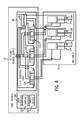
- FIG. 4 is a schematic diagram of an alternative embodiment of a fluid control unit configured to automatically adjust a penetration depth of ground engaging tools coupled to multiple frame sections.
- Embodiments disclosed herein may substantially reduce the cost and complexity associated with automatically controlling penetration depth of ground engaging tools within an agricultural implement.
- the agricultural implement system described below includes a controller configured to directly adjust a tow vehicle mounted depth control valve, thereby automatically maintaining a user-selectable penetration depth. Because the tow vehicle depth control valve is directly actuated, controllers and/or additional directional control valves, which may be coupled to the implement in alternative configurations to control penetration depth, may be obviated.
- an operator may input a desired penetration depth into a user interface mounted within a cab of the tow vehicle. The controller will then compare a measured penetration depth of the ground engaging tools to the input penetration depth.
- the controller will instruct the depth control valve to raise the implement. Conversely, if the penetration depth is shallower than desired, the controller will instruct the depth control valve to lower the implement. In this manner, the user-selected penetration depth will be maintained via direct actuation of the tow vehicle mounted depth control valve.
- FIG. 1 is a side view of an exemplary agricultural implement system, including an agricultural implement 10 .
- the implement 10 is designed to be towed behind a work vehicle, such as the illustrated tractor 12 .
- the implement 10 includes a tongue assembly 14 having a hitch used to attach to an appropriate tractor hitch 16 via a ball, clevis, or other coupling.
- a tongue of the implement 10 may be connected to a drawbar of the tractor, or a mast of the implement may be connected to a 3-point hitch of the tractor.
- the tongue assembly 14 is coupled to an implement frame 18 configured to support multiple ground engaging tools 20 .
- each ground engaging tool 20 includes a shank 22 and a tillage point 24 .
- ground engaging tools 20 such as coulters, disc blades and/or tines, may be employed in alternative embodiments.
- two ground engaging tools 20 are coupled to the frame 18 in the illustrated embodiment, it should be appreciated that alternative embodiments may include significantly more ground engaging tools.
- certain implements may include 2, 4, 6, 8, 10, 12, 14, 16, 18, 20, or more ground engaging tools 20 .
- the implement 10 includes a ground engaging wheel assembly 26 having a wheel 28 and an arm 30 .
- the wheel 28 which is pivotally coupled to a first end of the arm 30 via an axle 32 , is configured to support the implement 10 during tillage operations.
- the arm 30 is rotatably mounted to the frame 18 via a rockshaft 34 .
- a height or elevation of the frame 18 relative to the soil surface may be varied by rotating the arm 30 relative to the frame 18 . For example, rotating the arm 30 in a clockwise direction will increase the height of the frame 18 , thereby decreasing the penetration depth of the ground engaging tools 20 .
- a desired penetration depth may be particularly selected based on soil conditions, crop selection and/or other parameters associated with tillage operations.
- the height of the frame 18 may be increased to extract the ground engaging tools 20 from the soil, thereby facilitating transport of the implement 10 .
- the implement 10 includes a depth control cylinder 36 extending between the frame 18 and a second end of the arm 30 .
- the depth control cylinder 36 is fluidly coupled to a fluid control unit 38 of the tow vehicle 12 , and configured to rotate the arm 30 relative to the frame 18 .
- the fluid control unit 38 includes a depth control valve configured to selectively direct pressurized fluid to a cap side or a rod side of the cylinder 36 , thereby adjusting the height of the frame 18 relative to the soil surface.
- the fluid control unit 38 includes a controller configured to adjust the position of the depth control valve based on signals indicative of penetration depth of the ground engaging tools 20 .
- the implement 10 includes a sensor 40 communicatively coupled to the fluid control unit 38 , and configured to output signals indicative of the frame height.
- the fluid control unit 38 is configured to automatically control fluid flow to the depth control cylinder based on the signals to maintain a user-selectable penetration depth. For example, an operator may select a desired penetration depth of the ground engaging tools 20 via a user interface within the tow vehicle 12 .
- the fluid control unit 38 may automatically maintain the desired penetration depth by adjusting fluid flow to the depth control cylinder 36 . For example, if the controller determines that the penetration depth is deeper than desired, the fluid control unit 38 may increase the frame height, thereby reducing penetration depth. Conversely, if the controller determines that the penetration depth is shallower than desired, the fluid control unit 38 may decrease the height of the frame 18 to compensate.
- the senor 40 is configured to measure rotation of the arm 30 relative to the frame 18 , thereby enabling the fluid control unit 38 to determine ground engaging tool penetration depth based on the height of the frame 18 above the soil surface.
- the sensor 40 may include a rotary potentiometer coupled to the rockshaft 34 , and configured to output signals indicative of arm rotation.
- other embodiments may include a linear potentiometer configured to measure a position of the arm 30 relative to the frame 18 , a linear potentiometer configured to measure extension of a depth control cylinder rod, or a transducer (e.g., ultrasonic, electromagnetic, infrared, etc.) configured to measure a height of the frame 18 above the soil surface.
- a transducer e.g., ultrasonic, electromagnetic, infrared, etc.
- each depth control cylinder may be fluidly coupled to a respective depth control valve within the fluid control unit 38 . Consequently, a height of each frame section relative to the soil surface may be independently adjustable, thereby enabling the ground engaging tools 20 to maintain a substantially constant penetration depth despite variations in the soil surface.
- a manually operated depth stop valve located on the implement 10 may be obviated.
- an operator may adjust penetration depth without stopping the tow vehicle 12 , thereby substantially reducing the duration of tillage operations.
- controllers and/or directional control valves which may be coupled to the implement in certain embodiments to control penetration depth, may be obviated, thereby substantially reducing the cost and complexity of the automatic depth control system.
- FIG. 2 is a top view of an exemplary agricultural implement 10 that may be employed within the agricultural implement system of FIG. 1 .
- the implement frame 18 includes a center frame section 42 , a left frame section 44 and a right frame section 46 .
- Each frame section includes multiple ground engaging tools 20 , such as the illustrated tillage points, configured to till soil as the implement 10 is pulled through a field.
- each frame section includes two tool bars configured to support two rows of ground engaging tools 20 .
- the number of ground engaging tools 20 coupled to each tool bar may be particularly selected to provide a desired degree of tillage.
- the center frame section 42 is coupled to the left frame section 44 by two joints 48 , and to the right frame section 46 by two joints 48 .
- the joints 48 enable the height of each frame section to be independently adjusted relative to the soil surface.
- the joints 48 enable the left and right frame sections 44 and 46 to tilt relative to the center frame section 42 .
- each frame section may remain substantially parallel to the soil surface during tillage operations, thereby enabling the ground engaging tools 20 to maintain a substantially constant penetration depth despite variations in the soil surface.
- the left frame section 44 includes a first sensor 50 positioned at the front of the section 44 relative to the direction of travel, and a second sensor 52 positioned at the rear of the section 44 .
- Each sensor 50 and 52 is communicatively coupled to the fluid control unit, and configured to output signals indicative of the height of the sensor above the soil surface.
- each sensor 50 and 52 may include a transducer configured to emit a field (e.g., electromagnetic, ultrasonic, infrared, etc.) toward the soil surface, and to determine a distance between the sensor and the soil surface based on the received feedback.
- a field e.g., electromagnetic, ultrasonic, infrared, etc.
- the left frame section 44 also includes a first ground engaging wheel assembly 56 positioned at the front of the frame section 44 relative to the direction of travel, and a second ground engaging wheel assembly 58 positioned at the rear of the frame section 44 .
- each wheel assembly 56 and 58 includes a ground engaging wheel and a depth control cylinder configured to vary a height of the ground engaging wheel relative to the frame section 44 .
- each depth control cylinder may be fluidly coupled to a respective depth control valve within the fluid control unit. In such embodiments, the height of each ground engaging wheel relative to the frame section 44 will be independently adjustable.
- the fluid control unit may adjust the position of each ground engaging wheel to maintain the frame section 44 at a desired height and at a desired orientation (e.g., substantially parallel to the soil surface), thereby maintaining the ground engaging tools 20 at a desired penetration depth.
- the fluid control unit may adjust fluid flow to the depth control cylinders, thereby lowering the first ground engaging wheel and/or raising the second ground engaging wheel.
- the height and orientation of the left frame section 44 about an axis substantially perpendicular to the direction of travel may be substantially maintained.
- the right frame section 46 includes a front wheel assembly and a rear wheel assembly configured to adjust the height and orientation of the frame section.
- the center frame section 42 includes four ground engaging wheel assemblies configured to facilitate height adjustment and multi-axis variations in orientation of the frame section. As illustrated, the center frame section 42 includes a first sensor 60 positioned at a front left portion of the frame section, a second sensor 62 positioned at a front right portion of the frame section, a third sensor 64 positioned at a rear left portion of the frame section, and a fourth sensor 66 positioned at a rear right portion of the frame section.
- the sensors 60 , 62 , 64 and 66 are communicatively coupled to the fluid control unit, and configured to output signals indicative of the height of the sensor above the soil surface. Consequently, a controller within the fluid control unit may determine an orientation of the center frame section 42 about an axis perpendicular to the direction of travel and/or about an axis parallel to the direction of travel. The controller may also determine the average height of the frame section relative to the soil surface based on the signals from the sensors.
- the center frame section 42 includes a first ground engaging wheel assembly 68 positioned at the front left portion of the frame section, a second ground engaging wheel assembly 70 positioned at the front right portion of the frame section, a third ground engaging wheel assembly 72 positioned at the rear left portion of the frame section, and a fourth ground engaging wheel assembly 74 positioned at the rear right portion of the frame section.
- each wheel assembly 68 , 70 , 72 and 74 includes a ground engaging wheel and a depth control cylinder configured to vary a height of the ground engaging wheel relative to the center frame section 42 .
- each depth control cylinder may be fluidly coupled to a respective depth control valve within the fluid control unit.
- each ground engaging wheel relative to the frame section 42 will be independently adjustable. Consequently, the fluid control unit may adjust the position of each ground engaging wheel to maintain the frame section 44 at a desired height and at a desired orientation (e.g., substantially parallel to the soil surface), thereby maintaining the ground engaging tools 20 at a desired penetration depth. For example, if the sensors 60 , 62 , 64 and 66 indicate that the front of the frame section 42 is higher than the rear of the frame section, the fluid control unit may adjust fluid flow to the depth control cylinders, thereby lowering the first and second ground engaging wheels and/or raising the third and fourth ground engaging wheels.
- the fluid control unit may adjust fluid flow to the depth control cylinders, thereby lowering the first and third ground engaging wheels and/or raising the second and fourth ground engaging wheels.
- the height and orientation of the center frame section 42 about axes parallel and perpendicular to the direction of travel may be substantially maintained.
- each frame section 42 , 44 and 46 may include more or fewer frame sections.
- certain embodiments may include 1, 2, 3, 4, 5, 6, or more frame sections, in which a height and/or orientation of each frame section is individually adjustable.
- each ground engaging wheel assembly in the illustrated embodiment is controlled by an independent depth control valve within the fluid control unit, it should be appreciated that alternative embodiments may include multiple wheel assemblies controlled by a single depth control valve.
- the depth control cylinders of the first and second ground engaging wheel assemblies 68 and 70 of the center frame section 42 may be fluidly coupled to a first depth control valve (e.g., in a serial flow arrangement), while the depth control cylinders of the third and fourth ground engaging wheel assemblies 72 and 74 are fluidly coupled to a second depth control valve.
- the center frame section 42 may be tilted about an axis perpendicular to the direction of travel, but not parallel to the direction of travel.
- the depth control cylinders of the first and second ground engaging wheel assemblies 56 and 58 of the left frame section 44 may be fluidly coupled to a single depth control valve within the fluid control unit. In such a configuration, the height of the left frame section 44 may be adjustable, but the orientation may be fixed.
- FIG. 3 is a schematic diagram of an exemplary fluid control unit configured to automatically adjust a penetration depth of ground engaging tools on the agricultural implement.
- a first fluid conduit 76 and a second fluid conduit 78 extend to four depth control cylinders 36 .
- the depth control cylinders 36 are arranged in a serial flow configuration in which the cylinders 36 are fluidly coupled to one another by connecting conduits 80 .
- the serial flow configuration enables each cylinder 36 to extend and retract a substantially equal distance when pressurized fluid is supplied to the cylinders. While the illustrated embodiment includes four depth control cylinders 36 , it should be appreciated that alternative embodiments may include more or fewer cylinders (e.g., 1, 2, 3, 4, 5, 6, 7, 8, or more).
- certain implements may include ground engaging wheel assemblies having independent depth control cylinders.
- Alternative embodiments may include multiple wheel assemblies actuated by a single depth control cylinder 36 , or multiple groups of wheel assemblies, with each group being actuated by a single depth control cylinder 36 .
- alternative embodiments may include depth control cylinders 36 arranged in a parallel flow configuration in which each cylinder 36 is directly coupled to the first and second fluid conduits 76 and 78 .
- the first fluid conduit 76 is coupled to a cap side 82 of a first cylinder 36
- the second fluid conduit 78 is coupled to a rod side 84 of a fourth cylinder 36
- the rod side 84 of the first cylinder 36 is fluidly coupled to the cap side 82 of a second cylinder 36 via a first connecting conduit 80
- the rod side 84 of the second cylinder 36 is fluidly coupled to the cap side 82 of a third cylinder 36 via a second connecting conduit 80
- the rod side 84 of the third cylinder 36 is fluidly coupled to the cap side 82 of the fourth cylinder 36 via a third connecting conduit 80 .
- applying fluid pressure to the first conduit 76 induces the first depth control cylinder 36 to extend in a direction 86 .
- the remaining cylinders are also driven in the direction 86 as fluid from the rod side 84 of the first, second and third cylinders 36 is driven into the cap side 82 of the second, third and fourth cylinders 36 .
- applying fluid pressure to the second conduit 78 will induce each depth control cylinder 36 to retract in a direction 88 .
- the depth control cylinders 36 may be reversed such that the first fluid conduit 76 is coupled to the rod side 84 of the first cylinder, the second fluid conduit 78 is coupled to the cap side 82 of the fourth cylinder 36 , and the connecting conduits 80 extend from the cap side 82 of one cylinder to the rod side 84 of a subsequent cylinder.
- applying fluid pressure to the first fluid conduit 76 will induce the depth control cylinders 36 to retract in the direction 88
- applying fluid pressure to the second conduit 78 will induce the cylinders 36 to extend in the direction 86 .
- each depth control cylinder 36 includes a barrel 90 having an end cap 92 , a gland 94 , and a piston 96 .
- the cap side 82 is defined by a volume formed from the piston 96 , barrel 90 and end cap 92
- the rod side 84 is defined by a volume formed from the piston 96 , barrel 90 and gland 94 .
- a rod 98 is coupled to the piston 96 such that movement of the piston 96 drives the rod 98 to translate in the direction 86 and/or 88 .
- various seals may be employed between the rod 98 and the gland 94 to block a flow of fluid from exiting the cylinder 36 .
- the piston 96 includes additional seals to block a flow of fluid between the cap side 82 and the rod side 84 of the cylinder 36 .
- applying fluid pressure to the first conduit 76 increases pressure to the cap side 82 of each cylinder 36 , thereby driving the piston 96 and the rod 98 in the direction 86 .
- applying fluid pressure to the second conduit 78 increases pressure to the rod side 84 of each cylinder 36 , thereby driving the piston 96 and the rod 98 in the direction 88 .
- increasing pressure to one conduit may be accompanied by a decrease in pressure to the other conduit to facilitate movement of each piston 96 within the respective barrel 90 .
- the depth control cylinders 36 may be particularly configured to operate based on pneumatic or hydraulic fluid pressure.
- the first conduit 76 and the second conduit 78 are coupled to a depth control valve 100 (e.g., directional control valve) within the fluid control unit 38 .
- the depth control valve 100 is configured to control fluid flow from a fluid power supply to the depth control cylinders 36 .
- the directional control valve 100 is a three-position/four-way hydraulic valve configured to control a flow of hydraulic fluid to the cylinders 36 .
- a pneumatic directional control valve 100 may be employed in embodiments utilizing pneumatic cylinders 36 .
- a supply conduit 102 and a return conduit 104 are coupled to the depth control valve 100 .
- the supply conduit 102 is configured to provide fluid to the fluid control unit 38
- the return conduit 104 enables fluid to return to the fluid power supply.
- the fluid power supply may be coupled to the tow vehicle 12 .
- the depth control valve 100 includes a first position 106 configured to block fluid flow from the supply and return conduits 102 and 104 to the first and second conduits 76 and 78 . While the depth control valve 100 is in the first position 106 , fluid pressure within the cap side 82 and the rod side 84 of each cylinder 36 will be maintained, thereby holding the ground engaging tools 20 at a desired penetration depth.
- the depth control valve 100 also includes a second position 108 that establishes a fluid connection between the supply conduit 102 and the first conduit 76 , and between the return conduit 104 and the second conduit 78 .
- the depth control valve 100 While the depth control valve 100 is in the second position 108 , fluid will flow from the supply conduit 102 to the cap side 82 of the first cylinder 36 and from the rod side 84 of the fourth cylinder 36 to the return conduit 104 , thereby inducing the piston rod 98 of each cylinder 36 to extend in the direction 86 . Consequently, transitioning the depth control valve 100 to the second position 108 drives the ground engaging wheels downwardly, thereby decreasing the penetration depth of the ground engaging tools 20 . Furthermore, the depth control valve 100 includes a third position 110 that establishes a fluid connection between the supply conduit 102 and the second conduit 78 , and between the return conduit 104 and the first conduit 76 .
- the depth control valve 100 includes two actuators 112 and 114 configured to adjust the position of the valve 100 .
- the first actuator 112 is a solenoid configured to drive the depth control valve 100 to the second position 108
- the second actuator 114 is a solenoid configured to drive the valve 100 to the third position 110 .
- Both the first and second actuators 112 and 114 are communicatively coupled to a controller 116 configured to adjust the position of the depth control valve 100 . Consequently, the fluid control unit controller 116 may vary the penetration depth of the ground engaging tools 20 by adjusting the position of the depth control valve 100 .
- the controller 116 may increase the penetration depth of the ground engaging tools 20 by driving the depth control valve 100 to the third position 110 via the second actuator 114 .
- the controller 116 may also decrease the penetration depth of the ground engaging tools 20 by driving the depth control valve 100 to the second position 108 via the first actuator 112 .
- the controller 116 is communicatively coupled to a user interface 118 within the tow vehicle 12 .
- the user interface 118 may be located within an interior of a tractor to facilitate access by an operator.
- the user interface 118 includes a display 120 and an input device 122 .
- the display 120 may be configured to present a visual and/or numeric representation of the penetration depth of the ground engaging tools.
- the sensor 40 may be configured to output signals indicative of a height of the implement frame above the soil surface.
- the controller 116 may receive these signals and compute a penetration depth of the ground engaging tools based on the frame height.
- the controller 116 may then output signals indicative of the penetration depth to the user interface 118 such that the penetration depth may be presented to the operator via the display 120 .
- the controller 116 may receive signals from each sensor, and compute the penetration depth of ground engaging tools of each frame section. In addition, the controller 116 may also be configured to compute an average height and/or an orientation of each frame section based on the signals. Such information may be sent to the user interface 118 and presented on the display 120 as a graphical and/or numeric representation of the information. As will be appreciated, the controller 116 may be communicatively linked to the user interface 118 and/or the sensor 40 by a wireless connection, a wired connection, or an optical fiber connection, for example. Furthermore, the communication links may employ any suitable communication protocol such as CAN Bus or ISO Bus, for example.
- the operator may input a desired penetration depth of the ground engaging tools via the input device 122 .
- the input device 122 may include a numeric keypad that enables an operator to input a desired penetration depth in predetermined units (e.g., inches, centimeters, etc.).
- the display 120 may present a numeric representation of the desired penetration depth and a numeric representation of the measured penetration depth of each ground engaging tool.
- the user interface 122 may also enable the operator to initiate an automatic adjustment of the frame height to transition the actual penetration depth of the ground engaging tools to the desired penetration depth. For example, if the measured penetration depth is shallower than the desired penetration depth, the fluid control unit 118 may automatically increase the penetration depth of the ground engaging tools.
- the controller 116 may first receive signals indicative of the frame height from the sensor 40 . The controller 116 may then compute the penetration depth of the ground engaging tools based on the signals. If the computed penetration depth is shallower than the desired penetration depth, the controller 116 will activate the second actuator 114 to transition the depth control valve 100 to the third position 110 . As a result, a fluid connection will be established between the supply conduit 102 and the second conduit 78 , and between the return conduit 104 and the first conduit 76 . Consequently, pressurized fluid will flow into the rod side 84 of the fourth depth control cylinder 36 , thereby inducing each piston rod 98 to retract.
- the controller 116 will transition the depth control valve 100 to the first position 106 , thereby blocking fluid flow to the cylinders 36 .
- the controller 116 will activate the first actuator 112 to transition the depth control valve 100 to the second position 108 .
- a fluid connection will be established between the supply conduit 102 and the first conduit 76 , and between the return conduit 104 and the second conduit 78 . Consequently, pressurized fluid will flow into the cap side 82 of the first depth control cylinder 36 , thereby inducing each piston rod 98 to extend.
- the respective ground engaging wheels will move downwardly relative to the frame, thereby raising the height of the frame and decreasing the penetration depth of the ground engaging tools.
- the controller 116 will transition the depth control valve 100 to the first position 106 , thereby blocking fluid flow to the cylinders 36 .
- the controller 116 may periodically adjust fluid flow to the depth control cylinders 36 as the implement 10 is pulled through a field to ensure that the penetration depth of the ground engaging tools 20 remains within a desired tolerance. For example, the controller 116 may compare the measured penetration depth to the desired penetration depth at discrete intervals (e.g., 0.1 Hz, 0.5 Hz, 1 Hz, 2 Hz, etc.). If the difference between the measured penetration depth and the desired penetration depth is greater than a predetermined tolerance (e.g., 1 inch, 0.5 inches, 0.25 inches, 0.1 inches, etc.), the controller 116 may actuate the depth control valve 100 to either extend or retract the depth control cylinders 36 , thereby compensating for the variation in penetration depth.
- a predetermined tolerance e.g., 1 inch, 0.5 inches, 0.25 inches, 0.1 inches, etc.
- the tolerance may be manually input (e.g., via the input device 122 ), thereby enabling an operator to specify the desired tolerance.
- a first tolerance may be employed to determine whether the penetration depth is shallower than desired, and a second tolerance may be employed to determine whether the penetration depth is deeper than desired.
- FIG. 4 is a schematic diagram of an alternative embodiment of a fluid control unit 38 configured to automatically adjust a penetration depth of ground engaging tools coupled to multiple frame sections.
- the fluid control unit 38 includes a first depth control valve 124 configured to adjust fluid flow to a first depth control cylinder 126 , a second depth control valve 128 configured to adjust fluid flow to a second depth control cylinder 130 , and a third depth control valve 132 configured to adjust fluid flow to a third depth control cylinder 134 .
- each depth control valve 124 , 128 and 132 is a three-position/four-way hydraulic valve configured to control a flow of hydraulic fluid to a respective cylinder 126 , 130 and 134 .
- each depth control valve includes two actuators communicatively coupled to the controller 116 and configured to adjust the position of the respective valve. Consequently, the controller 116 may adjust fluid flow to each cylinder 126 , 130 and 134 by adjusting the position of a respective depth control valve.
- each depth control cylinder is coupled to a ground engaging wheel assembly of a respective frame section.
- the implement 10 may include three frame sections.
- the first depth control cylinder 126 may adjust the height of the first frame section
- the second depth control cylinder 130 may adjust the height of the second frame section
- the third depth control cylinder 134 may adjust the height of the third frame section.
- each frame section may include a single ground engaging wheel assembly, actuated by a respective depth control cylinder.
- each depth control cylinder may be configured to actuate multiple ground engaging wheel assemblies (e.g., via a linkage) within a respective frame section.
- each depth control valve may be fluidly coupled to multiple depth control cylinders (e.g., in a serial flow arrangement) within a respective frame section.
- the fluid control unit 38 may independently adjust the height of each frame section, thereby enabling the ground engaging tools to maintain a desired penetration depth despite variations in the soil surface.
- depth control valves are employed in the illustrated embodiment to control the height of three frame sections, it should be appreciated that alternative embodiments may include more or fewer depth control valves to control the height of more or fewer frame sections.
- certain embodiments may include 1, 2, 3, 4, 5, 6, or more frame sections.
- the number of depth control valves within the fluid control unit 38 may correspond to the number of frame sections, thereby facilitating independent height adjustment of each frame section.
- multiple depth control valves may be coupled to multiple depth control cylinders within a single frame section, thereby enabling the fluid control unit 38 to adjust the height and the orientation of the frame section.
- each frame section of a multi-section implement may include a first ground engaging wheel assembly positioned at a front of the frame section, and a second ground engaging wheel assembly positioned at a rear of the frame section.
- each ground engaging wheel assembly may include a depth control cylinder fluidly coupled to a respective depth control valve within the fluid control unit 38 . Consequently, the controller 116 may be configured to tilt the frame section by varying the height of the ground engaging wheels of the first and second ground engaging wheel assemblies.
- certain frame sections may include four independently controllable ground engaging wheel assemblies to control tilt about multiple axes.
- other frame sections may include 1, 2, 3, 4, 5, 6, or more independently adjustable wheel assemblies and a corresponding number of depth control valves within the fluid control unit 38 , thereby enabling the fluid control unit 38 to vary the height and the orientation of each frame section.
- the first depth control cylinder 126 includes a sensor 136 having a linear potentiometer configured to measure a position of the piston rod relative to the barrel of the cylinder. Consequently, the sensor 136 will output signals to the controller 116 indicative of the extension and retraction of the rod.
- each depth control cylinder is configured to adjust the height of a ground engaging wheel relative to the frame of the implement, thereby varying the penetration depth of the ground engaging tools. Therefore, the controller 116 may determine the penetration depth of the ground engaging tools based on the signals output from the sensor 136 .
- the second depth control cylinder 130 includes a second sensor 138
- the third depth control cylinder 134 includes a third sensor 140 .
- each depth control cylinder 126 , 130 and 134 is configured to adjust the height of a respective frame section
- the controller 116 may automatically maintain a desired penetration depth of the ground engaging tools by receiving signals from the sensors 136 , 138 and 140 , and adjusting fluid flow to the cylinders 126 , 130 and 134 to compensate for variations in the computed penetration depth.
- the controller 116 may adjust the position of the first and second depth control valves 124 and 128 to tilt the frame section to an orientation substantially parallel to the soil surface, thereby substantially maintaining the penetration depth of the ground engaging tools.
Landscapes
- Life Sciences & Earth Sciences (AREA)
- Engineering & Computer Science (AREA)
- Mechanical Engineering (AREA)
- Soil Sciences (AREA)
- Environmental Sciences (AREA)
- Lifting Devices For Agricultural Implements (AREA)
Abstract
Description
Claims (20)
Priority Applications (3)
| Application Number | Priority Date | Filing Date | Title |
|---|---|---|---|
| US13/041,563 US8857530B2 (en) | 2011-03-07 | 2011-03-07 | Automatic depth control system for an agricultural implement |
| CA2753800A CA2753800C (en) | 2011-03-07 | 2011-09-29 | Automatic depth control system for an agricultural implement |
| RU2012108587/13A RU2012108587A (en) | 2011-03-07 | 2012-03-06 | AUTOMATIC DEPTH SYSTEM FOR AGRICULTURAL WEAPONS |
Applications Claiming Priority (1)
| Application Number | Priority Date | Filing Date | Title |
|---|---|---|---|
| US13/041,563 US8857530B2 (en) | 2011-03-07 | 2011-03-07 | Automatic depth control system for an agricultural implement |
Publications (2)
| Publication Number | Publication Date |
|---|---|
| US20120227992A1 US20120227992A1 (en) | 2012-09-13 |
| US8857530B2 true US8857530B2 (en) | 2014-10-14 |
Family
ID=46787395
Family Applications (1)
| Application Number | Title | Priority Date | Filing Date |
|---|---|---|---|
| US13/041,563 Active 2032-11-24 US8857530B2 (en) | 2011-03-07 | 2011-03-07 | Automatic depth control system for an agricultural implement |
Country Status (3)
| Country | Link |
|---|---|
| US (1) | US8857530B2 (en) |
| CA (1) | CA2753800C (en) |
| RU (1) | RU2012108587A (en) |
Cited By (40)
| Publication number | Priority date | Publication date | Assignee | Title |
|---|---|---|---|---|
| US9320190B2 (en) * | 2011-06-03 | 2016-04-26 | Precision Planting Llc | Agricultural toolbar apparatus, systems and methods |
| EP2739128B1 (en) | 2011-08-05 | 2016-07-20 | Precision Planting LLC | Apparatus, systems and methods for row unit downforce control |
| US9554504B2 (en) | 2014-02-19 | 2017-01-31 | Shane Houck | Depth control for a seed planting system |
| US20180192569A1 (en) * | 2015-07-08 | 2018-07-12 | Agro Intelligence Aps | A plough system |
| US10051774B2 (en) | 2016-09-16 | 2018-08-21 | Cnh Industrial Canada, Ltd. | Common lift/lower ground entrance point |
| US10225983B2 (en) | 2017-03-27 | 2019-03-12 | Cnh Industrial America Llc | Remote hydraulic positioning of an implement stabilizer wheel |
| US20190235529A1 (en) * | 2018-01-26 | 2019-08-01 | Cnh Industrial Canada, Ltd. | System and method for monitoring frame levelness of an agricultural implement |
| US10440876B2 (en) | 2016-03-02 | 2019-10-15 | Deere & Company | Automated leveling and depth control system of a work machine and method thereof |
| US10440877B2 (en) | 2016-08-18 | 2019-10-15 | Cnh Industrial America Llc | Residue management based on topography by an agricultural tillage implement |
| US10542656B2 (en) | 2017-04-27 | 2020-01-28 | Cnh Industrial America Llc | Remote electrical positioning of an implement stabilizer wheel |
| US20200084951A1 (en) * | 2016-12-16 | 2020-03-19 | Agco Corporation | Implement contouring toolbar |
| US10645856B2 (en) | 2017-04-28 | 2020-05-12 | Cnh Industrial America Llc | Remote hydraulic actuation and positioning of a plurality of implement stabilizer wheels |
| US10667454B2 (en) | 2016-03-02 | 2020-06-02 | Deere & Company | Hydraulic control system of an implement for a work machine and method thereof |
| US10704573B2 (en) | 2017-08-29 | 2020-07-07 | Cnh Industrial Canada, Ltd. | System and method for rephasing fluid-driven actuators |
| US10752237B2 (en) | 2017-10-27 | 2020-08-25 | Cnh Industrial America Llc | System and method for automatically leveling an agricultural implement |
| US10750653B2 (en) | 2016-03-02 | 2020-08-25 | Deere & Company | Automated leveling and depth control system of a work machine and method thereof |
| US10779454B2 (en) | 2018-01-30 | 2020-09-22 | Exmark Manufacturing Company, Incorporated | Soil penetrating apparatus with depth control |
| US10813264B2 (en) | 2018-08-10 | 2020-10-27 | Cnh Industrial America Llc | Depth control for ground engaging tools of an implement |
| US10827665B2 (en) | 2018-09-19 | 2020-11-10 | Deere & Company | Tool height control for ground engaging tools |
| US10939604B2 (en) | 2018-10-01 | 2021-03-09 | Deere & Company | Multi-sensor tool height control for ground engaging tools |
| US10973171B2 (en) | 2018-10-17 | 2021-04-13 | Cnh Industrial America Llc | System and method for monitoring field profiles based on data from multiple types of sensors |
| US11019762B2 (en) | 2018-07-12 | 2021-06-01 | Cnh Industrial Canada, Ltd. | Precision depth control of seed planting units of an agricultural implement |
| US11104330B2 (en) * | 2017-11-15 | 2021-08-31 | Autonomous Stuff, LLC | Systems and method for controlling a vehicle |
| US11147205B2 (en) * | 2019-02-19 | 2021-10-19 | Cnh Industrial America Llc | System and method for monitoring tool float on an agricultural implement |
| US11206753B2 (en) | 2019-06-14 | 2021-12-28 | Cnh Industrial America Llc | System and method for controlling an agricultural implement during the performance of a tillage operation |
| US11297757B2 (en) | 2018-02-13 | 2022-04-12 | Cnh Industrial America Llc | System for monitoring the displacement of a ground engaging tool |
| US11419254B2 (en) * | 2019-10-28 | 2022-08-23 | Cnh Industrial Canada, Ltd. | System and method for detecting levelness of tools of a tillage implement based on tool loading |
| US11432454B2 (en) | 2017-08-23 | 2022-09-06 | Cnh Industrial Canada, Ltd. | System and method for spraying fluid onto seeds dispensed from a planter |
| US11470757B2 (en) | 2019-04-25 | 2022-10-18 | Cnh Industrial America Llc | Plough |
| US11558993B2 (en) | 2020-03-26 | 2023-01-24 | Cnh Industrial America Llc | Soil monitoring system for an agricultural tillage implement |
| US11602092B2 (en) | 2020-03-26 | 2023-03-14 | Cnh Industrial America Llc | Frame control system for an agricultural implement |
| US11617294B2 (en) | 2020-03-26 | 2023-04-04 | Cnh Industrial America Llc | Orientation control system for an agricultural implement |
| US11638393B2 (en) | 2020-03-26 | 2023-05-02 | Cnh Industrial America Llc | Ground engaging tool monitoring system |
| US11665991B2 (en) | 2019-09-24 | 2023-06-06 | Cnh Industrial America Llc | System and method for monitoring the levelness of a multi-wing agricultural implement |
| US11730076B2 (en) | 2020-03-26 | 2023-08-22 | Cnh Industrial America Llc | Control system for an agricultural implement |
| US11832545B2 (en) | 2019-12-31 | 2023-12-05 | Cnh Industrial America Llc | System and method for operating ground engaging tools based on measured soil moisture |
| US11895941B2 (en) | 2019-09-23 | 2024-02-13 | Cnh Industrial America Llc | Tillage system with variable fertilizer application |
| US12022756B2 (en) | 2020-03-26 | 2024-07-02 | Cnh Industrial America Llc | Orientation control system for an agricultural implement |
| US12052941B2 (en) | 2019-12-19 | 2024-08-06 | Cnh Industrial America Llc | System and method for calibrating tool depth of an agricultural implement based on frame position |
| RU232841U1 (en) * | 2024-07-15 | 2025-03-24 | Федеральное государственное бюджетное образовательное учреждение высшего образования "Красноярский государственный аграрный университет" | Device for adjusting the position of the cultivator's working parts |
Families Citing this family (21)
| Publication number | Priority date | Publication date | Assignee | Title |
|---|---|---|---|---|
| RU2014144625A (en) | 2013-11-13 | 2016-05-27 | СиЭнЭйч ИНДАСТРИАЛ АМЕРИКА ЭлЭлСи | LIFTING LEVER LIFTING SYSTEM |
| US9661798B2 (en) | 2013-11-13 | 2017-05-30 | Cnh Industrial America Llc | Agricultural tillage implement wheel control |
| CA2867274C (en) | 2013-11-13 | 2018-07-24 | Cnh Industrial America Llc | Agricultural tillage implement wheel control |
| WO2015164811A1 (en) * | 2014-04-25 | 2015-10-29 | Cnh Industrial America Llc | System and method for controlling an agricultural system based on soil analysis |
| US10420271B2 (en) | 2014-11-10 | 2019-09-24 | Cnh Industrial America Llc | Fully adjustable lift system |
| US9826677B2 (en) | 2014-12-16 | 2017-11-28 | Cnh Industrial Canada, Ltd. | Seed implement incorporating a down pressure sensing and adjustment system |
| US9714923B2 (en) * | 2015-05-08 | 2017-07-25 | Caterpillar Inc. | Topographic wear monitoring system for ground engaging tool |
| US10188027B2 (en) | 2015-05-20 | 2019-01-29 | Kinze Manufacturing, Inc. | Row unit with shank opener |
| DE102016002670A1 (en) * | 2015-12-28 | 2017-06-29 | Pöttinger Landtechnik Gmbh | Display of the support frame height at the operator terminal |
| CN109068574B (en) | 2016-02-19 | 2022-06-10 | 精密种植有限责任公司 | Agricultural trench depth system, method and device |
| US11963490B2 (en) * | 2016-07-22 | 2024-04-23 | Precision Planting Llc | Implements, systems, and methods for applying stress to early stage agricultural plants of agricultural fields |
| US10561052B2 (en) * | 2017-04-25 | 2020-02-18 | Cnh Industrial Canada, Ltd. | Automatic fore/aft leveling trim function in a towable tillage implement |
| US10820475B2 (en) * | 2017-04-27 | 2020-11-03 | Cnh Industrial America Llc | Agricultural implement and procedure for on-the-go soil nitrate testing |
| US11122725B2 (en) * | 2017-06-21 | 2021-09-21 | Honey Bee Manufacturing Ltd. | Tillage apparatuses and related methods |
| BR112020017522B1 (en) | 2018-03-01 | 2023-12-26 | Precision Planting Llc | AGRICULTURE DITCH DEPTH DEPTH SYSTEMS AND APPARATUS |
| US10918005B2 (en) * | 2018-05-23 | 2021-02-16 | Deere & Company | Implement weight transfer monitoring and wing control |
| SE545373C2 (en) * | 2020-10-30 | 2023-07-18 | Vaederstad Holding Ab | Agricultural implements for tillage and procedure for determining the working depth of tillage agricultural implements |
| US12114584B2 (en) | 2020-10-30 | 2024-10-15 | Honey Bee Manufacturing Ltd. | Agricultural implement with tine assembly |
| DE102021108388A1 (en) | 2021-04-01 | 2022-10-06 | Horsch Maschinen Gmbh | tillage device |
| US12364176B2 (en) | 2021-06-16 | 2025-07-22 | Honey Bee Manufacturing Ltd. | Agricultural apparatuses and related methods |
| DK182096B1 (en) * | 2022-10-06 | 2025-08-13 | Cmn Maskintec As | Row cleaner with automatic distance regulation relative to the ground |
Citations (55)
| Publication number | Priority date | Publication date | Assignee | Title |
|---|---|---|---|---|
| US2851014A (en) | 1956-12-17 | 1958-09-09 | Ionic Electrostatic Corp | Piston rod control mechanism |
| US3666284A (en) | 1968-07-23 | 1972-05-30 | Deere & Co | Hydraulic depth control for drawn implement carriers having pivoted outer frames |
| CA1043003A (en) | 1976-10-18 | 1978-11-21 | James M. Sakundiak | Depth sensing system for tillage implements |
| US4221266A (en) * | 1978-10-13 | 1980-09-09 | International Harvester Company | Digital memory depth tillage system |
| GB2056692A (en) | 1979-08-18 | 1981-03-18 | Bosch Gmbh Robert | Magnetic measurement of position and/or speed of a piston |
| US4279138A (en) | 1978-04-20 | 1981-07-21 | C. Van Der Lely N. V. | Vehicle with a lifting device responsive to ground irregularities |
| US4286386A (en) | 1977-09-06 | 1981-09-01 | Long Irvin E | Electro-mechanical displacement measuring device |
| US4306732A (en) | 1979-12-10 | 1981-12-22 | J. E. Love Company | Depth control for agricultural implement |
| US4355688A (en) | 1981-01-29 | 1982-10-26 | Deere & Company | Agricultural implement and depth control therefor |
| GB2106984A (en) | 1981-09-24 | 1983-04-20 | Gewerk Eisenhuette Westfalia | Hydraulic ram with stroke indication |
| DE3139638A1 (en) | 1981-10-06 | 1983-04-21 | Hydrolektric GmbH, 6053 Obertshausen | Cylinder with piston and piston rod, in particular for control purposes |
| US4471304A (en) | 1979-11-14 | 1984-09-11 | Festo-Maschinenfabrik Gottlieb Stoll | Fluid-powered actuator having a cylinder with magnetic field detectors thereon and a magnetized piston rod |
| US4506898A (en) | 1984-02-02 | 1985-03-26 | Hesston Corporation | Drift eliminator for series hydraulic lift system on tillage implements and the like |
| US4518044A (en) | 1982-03-22 | 1985-05-21 | Deere & Company | Vehicle with control system for raising and lowering implement |
| US4600060A (en) | 1983-10-28 | 1986-07-15 | Deere & Company | Depth sensing structure for an agricultural implement |
| US4622884A (en) | 1981-04-10 | 1986-11-18 | Buchl Andrew F | Floating piston depth control apparatus |
| US4646620A (en) | 1983-07-01 | 1987-03-03 | Buchl Andrew F | Automatic depth control system |
| US4723608A (en) | 1986-09-30 | 1988-02-09 | Deere & Company | Depth sensing skid assembly |
| US4839591A (en) | 1986-12-16 | 1989-06-13 | Kayaba Kogyo Kabushiki-Kaisha | Magnetic stroke sensor for detecting the stroke of a fluid-power cylinder |
| DE3743552A1 (en) | 1987-12-22 | 1989-07-13 | Kloeckner Humboldt Deutz Ag | Hydraulic lifting device on a tractor |
| US4915014A (en) | 1985-05-08 | 1990-04-10 | Deere & Company | Disk harrow hydraulic wing balancing system |
| US4967851A (en) | 1989-10-03 | 1990-11-06 | Deere & Company | Agricultural depth control system including cross plumbed series cylinders |
| US5065681A (en) | 1990-10-10 | 1991-11-19 | Deere & Company | Hydraulic down pressure structure for an implement with multiple ground engaging tools |
| US5160239A (en) | 1988-09-08 | 1992-11-03 | Caterpillar Inc. | Coordinated control for a work implement |
| US5231352A (en) | 1989-02-15 | 1993-07-27 | Schaltbau Gesellschaft Mbh | Power actuator including magnetic position detector |
| US5277257A (en) | 1992-10-05 | 1994-01-11 | Deere & Company | Depth control mechanism for an implement |
| WO1994007037A1 (en) | 1992-09-23 | 1994-03-31 | Ab Rexroth Mecman | Positioning device for fluid cylinder |
| US5300918A (en) | 1992-03-06 | 1994-04-05 | Deere & Company | Shaft rotary position sensor |
| US5339906A (en) | 1993-01-08 | 1994-08-23 | Deere & Company | Positon feedback mechanism for an implement |
| US5366024A (en) | 1993-06-09 | 1994-11-22 | Deere & Company | Remotely adjustable depth control |
| US5427182A (en) | 1993-10-08 | 1995-06-27 | Deere & Company | Pressure relieving circuit for a series cylinder depth control |
| US5562165A (en) | 1994-03-14 | 1996-10-08 | Universite Laval | Hydraulic floating system for downpressure control of seeding tools |
| US5568760A (en) | 1994-08-02 | 1996-10-29 | Festo Kg | Fluid power cylinder with position indicator |
| US5957218A (en) | 1997-11-18 | 1999-09-28 | Deere & Company | Electrohydraulic control of implement lift cylinders |
| US5975215A (en) | 1999-01-20 | 1999-11-02 | Thurston Mfg. Co. | Means for controlling the stroke of a hydraulic cylinder |
| US6068064A (en) | 1998-05-20 | 2000-05-30 | Case Corporation | Agricultural implement with ground engaging tool and fluid circuit to control same |
| US6076611A (en) | 1998-12-17 | 2000-06-20 | Agco Corporation | Implement mounted depth control system |
| US6085846A (en) | 1999-07-01 | 2000-07-11 | Automatic Depth Control, Llc | Potentiometer-based gauge wheel device positioning system and method |
| US6129155A (en) | 1998-12-02 | 2000-10-10 | Caterpillar Inc. | Method and apparatus for controlling a work implement having multiple degrees of freedom |
| US6269885B1 (en) | 1999-12-15 | 2001-08-07 | Husco International, Inc. | Blade height control system for a motorized grader |
| US6371214B1 (en) | 1999-06-11 | 2002-04-16 | Caterpillar Inc. | Methods for automating work machine functions |
| US20030127235A1 (en) | 2000-06-10 | 2003-07-10 | Helmut Dannigkeit | Ground preparation device |
| US6698523B2 (en) | 2002-07-02 | 2004-03-02 | Husco International, Inc. | Electrohydraulic control system for implement lift cylinders |
| US20040079223A1 (en) | 2002-10-25 | 2004-04-29 | Steinlage David Lee | Directly actuated depth control |
| US20050173137A1 (en) | 2004-02-10 | 2005-08-11 | Buchl Gregg N. | Selective position control system and method |
| US6935253B2 (en) | 2003-11-07 | 2005-08-30 | Cnh America Llc | Depth control for seed planter |
| US20050274254A1 (en) | 1996-11-06 | 2005-12-15 | George Kadlicko | Hydraulic cylinder with position encoder |
| US7034527B2 (en) | 2003-05-06 | 2006-04-25 | Sri International | Systems of recording piston rod position information in a magnetic layer on a piston rod |
| US7063167B1 (en) | 2000-06-16 | 2006-06-20 | Case Corporation | Self leveling towed implement |
| US7178446B2 (en) | 2005-02-28 | 2007-02-20 | Caterpillar Inc | Cylinder rod with position sensor surface markings |
| US20070066374A1 (en) | 2005-09-19 | 2007-03-22 | Cnh America Llc | Compactor control logic for a cotton harvester |
| US7259553B2 (en) | 2005-04-13 | 2007-08-21 | Sri International | System and method of magnetically sensing position of a moving component |
| US20070214952A1 (en) | 2006-03-08 | 2007-09-20 | Gerhard Kossmann | Position measuring system for a hydraulic cylinder |
| US20090301743A1 (en) | 2008-06-05 | 2009-12-10 | James Henry | Method and apparatus for controlling the depth of an agricultural work unit mounted to a frame that can be raised and lowered by a cylinder assembly |
| US20090313860A1 (en) | 2008-06-24 | 2009-12-24 | Deere & Company | Automatic depth correction based on blade pitch |
-
2011
- 2011-03-07 US US13/041,563 patent/US8857530B2/en active Active
- 2011-09-29 CA CA2753800A patent/CA2753800C/en active Active
-
2012
- 2012-03-06 RU RU2012108587/13A patent/RU2012108587A/en not_active Application Discontinuation
Patent Citations (58)
| Publication number | Priority date | Publication date | Assignee | Title |
|---|---|---|---|---|
| US2851014A (en) | 1956-12-17 | 1958-09-09 | Ionic Electrostatic Corp | Piston rod control mechanism |
| US3666284A (en) | 1968-07-23 | 1972-05-30 | Deere & Co | Hydraulic depth control for drawn implement carriers having pivoted outer frames |
| CA1043003A (en) | 1976-10-18 | 1978-11-21 | James M. Sakundiak | Depth sensing system for tillage implements |
| US4286386A (en) | 1977-09-06 | 1981-09-01 | Long Irvin E | Electro-mechanical displacement measuring device |
| US4279138A (en) | 1978-04-20 | 1981-07-21 | C. Van Der Lely N. V. | Vehicle with a lifting device responsive to ground irregularities |
| US4221266A (en) * | 1978-10-13 | 1980-09-09 | International Harvester Company | Digital memory depth tillage system |
| GB2056692A (en) | 1979-08-18 | 1981-03-18 | Bosch Gmbh Robert | Magnetic measurement of position and/or speed of a piston |
| US4471304A (en) | 1979-11-14 | 1984-09-11 | Festo-Maschinenfabrik Gottlieb Stoll | Fluid-powered actuator having a cylinder with magnetic field detectors thereon and a magnetized piston rod |
| US4306732A (en) | 1979-12-10 | 1981-12-22 | J. E. Love Company | Depth control for agricultural implement |
| US4355688A (en) | 1981-01-29 | 1982-10-26 | Deere & Company | Agricultural implement and depth control therefor |
| US4622884A (en) | 1981-04-10 | 1986-11-18 | Buchl Andrew F | Floating piston depth control apparatus |
| GB2106984A (en) | 1981-09-24 | 1983-04-20 | Gewerk Eisenhuette Westfalia | Hydraulic ram with stroke indication |
| DE3139638A1 (en) | 1981-10-06 | 1983-04-21 | Hydrolektric GmbH, 6053 Obertshausen | Cylinder with piston and piston rod, in particular for control purposes |
| US4518044A (en) | 1982-03-22 | 1985-05-21 | Deere & Company | Vehicle with control system for raising and lowering implement |
| US4646620A (en) | 1983-07-01 | 1987-03-03 | Buchl Andrew F | Automatic depth control system |
| US4600060A (en) | 1983-10-28 | 1986-07-15 | Deere & Company | Depth sensing structure for an agricultural implement |
| US4506898A (en) | 1984-02-02 | 1985-03-26 | Hesston Corporation | Drift eliminator for series hydraulic lift system on tillage implements and the like |
| US4915014A (en) | 1985-05-08 | 1990-04-10 | Deere & Company | Disk harrow hydraulic wing balancing system |
| US4723608A (en) | 1986-09-30 | 1988-02-09 | Deere & Company | Depth sensing skid assembly |
| US4839591A (en) | 1986-12-16 | 1989-06-13 | Kayaba Kogyo Kabushiki-Kaisha | Magnetic stroke sensor for detecting the stroke of a fluid-power cylinder |
| DE3743552A1 (en) | 1987-12-22 | 1989-07-13 | Kloeckner Humboldt Deutz Ag | Hydraulic lifting device on a tractor |
| US5160239A (en) | 1988-09-08 | 1992-11-03 | Caterpillar Inc. | Coordinated control for a work implement |
| US5231352A (en) | 1989-02-15 | 1993-07-27 | Schaltbau Gesellschaft Mbh | Power actuator including magnetic position detector |
| US4967851A (en) | 1989-10-03 | 1990-11-06 | Deere & Company | Agricultural depth control system including cross plumbed series cylinders |
| US5065681A (en) | 1990-10-10 | 1991-11-19 | Deere & Company | Hydraulic down pressure structure for an implement with multiple ground engaging tools |
| US5300918A (en) | 1992-03-06 | 1994-04-05 | Deere & Company | Shaft rotary position sensor |
| WO1994007037A1 (en) | 1992-09-23 | 1994-03-31 | Ab Rexroth Mecman | Positioning device for fluid cylinder |
| US5277257A (en) | 1992-10-05 | 1994-01-11 | Deere & Company | Depth control mechanism for an implement |
| US5339906A (en) | 1993-01-08 | 1994-08-23 | Deere & Company | Positon feedback mechanism for an implement |
| US5366024A (en) | 1993-06-09 | 1994-11-22 | Deere & Company | Remotely adjustable depth control |
| US5427182A (en) | 1993-10-08 | 1995-06-27 | Deere & Company | Pressure relieving circuit for a series cylinder depth control |
| US5562165A (en) | 1994-03-14 | 1996-10-08 | Universite Laval | Hydraulic floating system for downpressure control of seeding tools |
| US5568760A (en) | 1994-08-02 | 1996-10-29 | Festo Kg | Fluid power cylinder with position indicator |
| US20050274254A1 (en) | 1996-11-06 | 2005-12-15 | George Kadlicko | Hydraulic cylinder with position encoder |
| US5957218A (en) | 1997-11-18 | 1999-09-28 | Deere & Company | Electrohydraulic control of implement lift cylinders |
| US6068064A (en) | 1998-05-20 | 2000-05-30 | Case Corporation | Agricultural implement with ground engaging tool and fluid circuit to control same |
| US6129155A (en) | 1998-12-02 | 2000-10-10 | Caterpillar Inc. | Method and apparatus for controlling a work implement having multiple degrees of freedom |
| US6076611A (en) | 1998-12-17 | 2000-06-20 | Agco Corporation | Implement mounted depth control system |
| US5975215A (en) | 1999-01-20 | 1999-11-02 | Thurston Mfg. Co. | Means for controlling the stroke of a hydraulic cylinder |
| US6371214B1 (en) | 1999-06-11 | 2002-04-16 | Caterpillar Inc. | Methods for automating work machine functions |
| US6085846A (en) | 1999-07-01 | 2000-07-11 | Automatic Depth Control, Llc | Potentiometer-based gauge wheel device positioning system and method |
| US6269885B1 (en) | 1999-12-15 | 2001-08-07 | Husco International, Inc. | Blade height control system for a motorized grader |
| US20030127235A1 (en) | 2000-06-10 | 2003-07-10 | Helmut Dannigkeit | Ground preparation device |
| US7063167B1 (en) | 2000-06-16 | 2006-06-20 | Case Corporation | Self leveling towed implement |
| US6698523B2 (en) | 2002-07-02 | 2004-03-02 | Husco International, Inc. | Electrohydraulic control system for implement lift cylinders |
| US20040079223A1 (en) | 2002-10-25 | 2004-04-29 | Steinlage David Lee | Directly actuated depth control |
| US6786130B2 (en) | 2002-10-25 | 2004-09-07 | Deere & Company | Directly actuated depth control |
| US7034527B2 (en) | 2003-05-06 | 2006-04-25 | Sri International | Systems of recording piston rod position information in a magnetic layer on a piston rod |
| US7307418B2 (en) | 2003-05-06 | 2007-12-11 | Sri International | Systems for recording position information in a magnetic layer on a piston rod |
| US6935253B2 (en) | 2003-11-07 | 2005-08-30 | Cnh America Llc | Depth control for seed planter |
| US20050173137A1 (en) | 2004-02-10 | 2005-08-11 | Buchl Gregg N. | Selective position control system and method |
| US7178446B2 (en) | 2005-02-28 | 2007-02-20 | Caterpillar Inc | Cylinder rod with position sensor surface markings |
| US7259553B2 (en) | 2005-04-13 | 2007-08-21 | Sri International | System and method of magnetically sensing position of a moving component |
| US20070066374A1 (en) | 2005-09-19 | 2007-03-22 | Cnh America Llc | Compactor control logic for a cotton harvester |
| US20070214952A1 (en) | 2006-03-08 | 2007-09-20 | Gerhard Kossmann | Position measuring system for a hydraulic cylinder |
| US20090301743A1 (en) | 2008-06-05 | 2009-12-10 | James Henry | Method and apparatus for controlling the depth of an agricultural work unit mounted to a frame that can be raised and lowered by a cylinder assembly |
| US8235130B2 (en) * | 2008-06-05 | 2012-08-07 | Cnh Canada, Ltd. | Method and apparatus for controlling the depth of an agricultural work unit mounted to a frame that can be raised and lowered by a cylinder assembly |
| US20090313860A1 (en) | 2008-06-24 | 2009-12-24 | Deere & Company | Automatic depth correction based on blade pitch |
Cited By (55)
| Publication number | Priority date | Publication date | Assignee | Title |
|---|---|---|---|---|
| US9320190B2 (en) * | 2011-06-03 | 2016-04-26 | Precision Planting Llc | Agricultural toolbar apparatus, systems and methods |
| US10765054B2 (en) | 2011-06-03 | 2020-09-08 | Precision Planting Llc | Agricultural toolbar apparatus, systems and methods |
| EP3106012B1 (en) | 2011-08-05 | 2019-12-11 | Precision Planting LLC | Agricultural planter having a plurality of row units, system and method for row unit downforce control |
| EP2739128B1 (en) | 2011-08-05 | 2016-07-20 | Precision Planting LLC | Apparatus, systems and methods for row unit downforce control |
| US9955623B2 (en) | 2011-08-05 | 2018-05-01 | Precision Planting Llc | Apparatus, systems and methods for row unit downforce control |
| EP3106012B2 (en) † | 2011-08-05 | 2023-10-11 | Precision Planting LLC | Agricultural planter having a plurality of row units, with a system for row unit downforce control |
| US10238023B2 (en) | 2011-08-05 | 2019-03-26 | Precision Planting Llc | Apparatus, systems and methods for row unit downforce control |
| US10834863B2 (en) | 2011-08-05 | 2020-11-17 | Precision Planting Llc | Apparatus, systems and methods for row unit downforce control |
| US9554504B2 (en) | 2014-02-19 | 2017-01-31 | Shane Houck | Depth control for a seed planting system |
| US11382258B1 (en) | 2014-02-19 | 2022-07-12 | Shane Houck | Depth control for a seed planting system |
| US10412881B1 (en) | 2014-02-19 | 2019-09-17 | Shane Houck | Depth control for a seed planting system |
| US20180192569A1 (en) * | 2015-07-08 | 2018-07-12 | Agro Intelligence Aps | A plough system |
| US12089516B2 (en) | 2016-03-02 | 2024-09-17 | Deere & Company | Automated leveling and depth control system of a work machine and method thereof |
| US10750653B2 (en) | 2016-03-02 | 2020-08-25 | Deere & Company | Automated leveling and depth control system of a work machine and method thereof |
| US11606893B2 (en) | 2016-03-02 | 2023-03-21 | Deere & Company | Automated leveling and depth control system of a work machine and method thereof |
| US10440876B2 (en) | 2016-03-02 | 2019-10-15 | Deere & Company | Automated leveling and depth control system of a work machine and method thereof |
| US10667454B2 (en) | 2016-03-02 | 2020-06-02 | Deere & Company | Hydraulic control system of an implement for a work machine and method thereof |
| US11716920B2 (en) | 2016-08-18 | 2023-08-08 | Cnh Industrial America Llc | Residue management based on topography by an agricultural tillage implement |
| US10440877B2 (en) | 2016-08-18 | 2019-10-15 | Cnh Industrial America Llc | Residue management based on topography by an agricultural tillage implement |
| US10051774B2 (en) | 2016-09-16 | 2018-08-21 | Cnh Industrial Canada, Ltd. | Common lift/lower ground entrance point |
| US11665989B2 (en) * | 2016-12-16 | 2023-06-06 | Agco Corporation | Implement contouring toolbar |
| US20200084951A1 (en) * | 2016-12-16 | 2020-03-19 | Agco Corporation | Implement contouring toolbar |
| US10225983B2 (en) | 2017-03-27 | 2019-03-12 | Cnh Industrial America Llc | Remote hydraulic positioning of an implement stabilizer wheel |
| US10542656B2 (en) | 2017-04-27 | 2020-01-28 | Cnh Industrial America Llc | Remote electrical positioning of an implement stabilizer wheel |
| US10645856B2 (en) | 2017-04-28 | 2020-05-12 | Cnh Industrial America Llc | Remote hydraulic actuation and positioning of a plurality of implement stabilizer wheels |
| US11432454B2 (en) | 2017-08-23 | 2022-09-06 | Cnh Industrial Canada, Ltd. | System and method for spraying fluid onto seeds dispensed from a planter |
| US10704573B2 (en) | 2017-08-29 | 2020-07-07 | Cnh Industrial Canada, Ltd. | System and method for rephasing fluid-driven actuators |
| US10752237B2 (en) | 2017-10-27 | 2020-08-25 | Cnh Industrial America Llc | System and method for automatically leveling an agricultural implement |
| US11104330B2 (en) * | 2017-11-15 | 2021-08-31 | Autonomous Stuff, LLC | Systems and method for controlling a vehicle |
| US20190235529A1 (en) * | 2018-01-26 | 2019-08-01 | Cnh Industrial Canada, Ltd. | System and method for monitoring frame levelness of an agricultural implement |
| US10838432B2 (en) | 2018-01-26 | 2020-11-17 | Cnh Industrial Canada, Ltd. | System and method for monitoring frame levelness of an agricultural implement |
| US11234353B2 (en) | 2018-01-30 | 2022-02-01 | Exmark Manufacturing Company, Incorporated | Actuator assembly |
| US10779454B2 (en) | 2018-01-30 | 2020-09-22 | Exmark Manufacturing Company, Incorporated | Soil penetrating apparatus with depth control |
| US11297757B2 (en) | 2018-02-13 | 2022-04-12 | Cnh Industrial America Llc | System for monitoring the displacement of a ground engaging tool |
| US11019762B2 (en) | 2018-07-12 | 2021-06-01 | Cnh Industrial Canada, Ltd. | Precision depth control of seed planting units of an agricultural implement |
| US10813264B2 (en) | 2018-08-10 | 2020-10-27 | Cnh Industrial America Llc | Depth control for ground engaging tools of an implement |
| US10827665B2 (en) | 2018-09-19 | 2020-11-10 | Deere & Company | Tool height control for ground engaging tools |
| US10939604B2 (en) | 2018-10-01 | 2021-03-09 | Deere & Company | Multi-sensor tool height control for ground engaging tools |
| US12144273B2 (en) | 2018-10-01 | 2024-11-19 | Deere & Company | Multi-sensor tool height control for ground engaging tools |
| US10973171B2 (en) | 2018-10-17 | 2021-04-13 | Cnh Industrial America Llc | System and method for monitoring field profiles based on data from multiple types of sensors |
| US11147205B2 (en) * | 2019-02-19 | 2021-10-19 | Cnh Industrial America Llc | System and method for monitoring tool float on an agricultural implement |
| US11470757B2 (en) | 2019-04-25 | 2022-10-18 | Cnh Industrial America Llc | Plough |
| US11206753B2 (en) | 2019-06-14 | 2021-12-28 | Cnh Industrial America Llc | System and method for controlling an agricultural implement during the performance of a tillage operation |
| US11895941B2 (en) | 2019-09-23 | 2024-02-13 | Cnh Industrial America Llc | Tillage system with variable fertilizer application |
| US11665991B2 (en) | 2019-09-24 | 2023-06-06 | Cnh Industrial America Llc | System and method for monitoring the levelness of a multi-wing agricultural implement |
| US11419254B2 (en) * | 2019-10-28 | 2022-08-23 | Cnh Industrial Canada, Ltd. | System and method for detecting levelness of tools of a tillage implement based on tool loading |
| US12052941B2 (en) | 2019-12-19 | 2024-08-06 | Cnh Industrial America Llc | System and method for calibrating tool depth of an agricultural implement based on frame position |
| US11832545B2 (en) | 2019-12-31 | 2023-12-05 | Cnh Industrial America Llc | System and method for operating ground engaging tools based on measured soil moisture |
| US11730076B2 (en) | 2020-03-26 | 2023-08-22 | Cnh Industrial America Llc | Control system for an agricultural implement |
| US11558993B2 (en) | 2020-03-26 | 2023-01-24 | Cnh Industrial America Llc | Soil monitoring system for an agricultural tillage implement |
| US12022756B2 (en) | 2020-03-26 | 2024-07-02 | Cnh Industrial America Llc | Orientation control system for an agricultural implement |
| US11638393B2 (en) | 2020-03-26 | 2023-05-02 | Cnh Industrial America Llc | Ground engaging tool monitoring system |
| US11617294B2 (en) | 2020-03-26 | 2023-04-04 | Cnh Industrial America Llc | Orientation control system for an agricultural implement |
| US11602092B2 (en) | 2020-03-26 | 2023-03-14 | Cnh Industrial America Llc | Frame control system for an agricultural implement |
| RU232841U1 (en) * | 2024-07-15 | 2025-03-24 | Федеральное государственное бюджетное образовательное учреждение высшего образования "Красноярский государственный аграрный университет" | Device for adjusting the position of the cultivator's working parts |
Also Published As
| Publication number | Publication date |
|---|---|
| US20120227992A1 (en) | 2012-09-13 |
| CA2753800A1 (en) | 2012-09-07 |
| CA2753800C (en) | 2016-10-25 |
| RU2012108587A (en) | 2013-09-20 |
Similar Documents
| Publication | Publication Date | Title |
|---|---|---|
| US8857530B2 (en) | Automatic depth control system for an agricultural implement | |
| CA2648442C (en) | Method and apparatus for controlling the depth of an agricultural work unit mounted to a frame that can be raised and lowered by a cylinder assembly | |
| CA2911387C (en) | Hydraulic work unit leveling and calibration system for an agricultural implement | |
| US20080257570A1 (en) | Electronic draft control for semi-trailed implements | |
| US20080257569A1 (en) | Electronic draft control for trailed implements | |
| CA2723157C (en) | Fluid control system for steerable agricultural implement | |
| CN105578867A (en) | Soil cultivation implement having a device for reconsolidation | |
| US11464153B2 (en) | Tillage implement with gauge wheels having hydraulic down-pressure | |
| EP3456163B1 (en) | Implement optimization by automated adjustments | |
| EP3732944B1 (en) | Method of controlling weight transfer of an implement and system thereof | |
| US10912244B2 (en) | Enhanced resolution fore/aft leveling of a towable tillage implement | |
| US8893629B2 (en) | System and method for coordinating product delivery with ground engaging tool position | |
| EP3420788B1 (en) | Agricultural machine and method for operating an agricultural machine | |
| US12564124B2 (en) | Two row agricultural planting implement having a lift and downforce actuator | |
| US20230105332A1 (en) | Hydraulic height control for agricultural tillage equipment | |
| CA3008044A1 (en) | A system for damping oscillations between a tractor and an agricultural implement during transport thereof | |
| US20190265737A1 (en) | Method for controlling a hydraulic top link of a three-point linkage | |
| EP3202243B1 (en) | Vehicle implement control | |
| US20250275496A1 (en) | Independent wing position control for an agricultural implement | |
| EP3389353A1 (en) | A system for controlling the working depth of an agricultural implement | |
| JPH10327604A (en) | Tractor tilling equipment |
Legal Events
| Date | Code | Title | Description |
|---|---|---|---|
| AS | Assignment |
Owner name: CNH CANADA, LTD., CANADA Free format text: ASSIGNMENT OF ASSIGNORS INTEREST;ASSIGNOR:HENRY, JIM;REEL/FRAME:025909/0905 Effective date: 20110304 |
|
| AS | Assignment |
Owner name: CNH INDUSTRIAL CANADA, LTD., CANADA Free format text: CHANGE OF NAME;ASSIGNOR:CNH CANADA, LTD.;REEL/FRAME:033032/0548 Effective date: 20140301 |
|
| STCF | Information on status: patent grant |
Free format text: PATENTED CASE |
|
| MAFP | Maintenance fee payment |
Free format text: PAYMENT OF MAINTENANCE FEE, 4TH YEAR, LARGE ENTITY (ORIGINAL EVENT CODE: M1551) Year of fee payment: 4 |
|
| MAFP | Maintenance fee payment |
Free format text: PAYMENT OF MAINTENANCE FEE, 8TH YEAR, LARGE ENTITY (ORIGINAL EVENT CODE: M1552); ENTITY STATUS OF PATENT OWNER: LARGE ENTITY Year of fee payment: 8 |
|
| MAFP | Maintenance fee payment |
Free format text: PAYMENT OF MAINTENANCE FEE, 12TH YEAR, LARGE ENTITY (ORIGINAL EVENT CODE: M1553); ENTITY STATUS OF PATENT OWNER: LARGE ENTITY Year of fee payment: 12 |