US8854811B2 - Electronic device with cover plate - Google Patents

Electronic device with cover plate Download PDF

Info

Publication number
US8854811B2
US8854811B2 US12/821,240 US82124010A US8854811B2 US 8854811 B2 US8854811 B2 US 8854811B2 US 82124010 A US82124010 A US 82124010A US 8854811 B2 US8854811 B2 US 8854811B2
Authority
US
United States
Prior art keywords
plate
button
groove
housing
electronic device
Prior art date
Legal status (The legal status is an assumption and is not a legal conclusion. Google has not performed a legal analysis and makes no representation as to the accuracy of the status listed.)
Active, expires
Application number
US12/821,240
Other versions
US20110094766A1 (en
Inventor
Wen-Chieh CHENG
Yao-Ting Lee
Current Assignee (The listed assignees may be inaccurate. Google has not performed a legal analysis and makes no representation or warranty as to the accuracy of the list.)
Wistron Corp
Original Assignee
Wistron Corp
Priority date (The priority date is an assumption and is not a legal conclusion. Google has not performed a legal analysis and makes no representation as to the accuracy of the date listed.)
Filing date
Publication date
Application filed by Wistron Corp filed Critical Wistron Corp
Assigned to WISTRON CORP. reassignment WISTRON CORP. ASSIGNMENT OF ASSIGNORS INTEREST (SEE DOCUMENT FOR DETAILS). Assignors: CHENG, WEN-CHIEH, LEE, YAO-TING
Publication of US20110094766A1 publication Critical patent/US20110094766A1/en
Application granted granted Critical
Publication of US8854811B2 publication Critical patent/US8854811B2/en
Active legal-status Critical Current
Adjusted expiration legal-status Critical

Links

Images

Classifications

    • GPHYSICS
    • G06COMPUTING; CALCULATING OR COUNTING
    • G06FELECTRIC DIGITAL DATA PROCESSING
    • G06F1/00Details not covered by groups G06F3/00 - G06F13/00 and G06F21/00
    • G06F1/16Constructional details or arrangements
    • G06F1/18Packaging or power distribution
    • G06F1/181Enclosures
    • GPHYSICS
    • G06COMPUTING; CALCULATING OR COUNTING
    • G06FELECTRIC DIGITAL DATA PROCESSING
    • G06F1/00Details not covered by groups G06F3/00 - G06F13/00 and G06F21/00
    • G06F1/16Constructional details or arrangements
    • G06F1/1613Constructional details or arrangements for portable computers
    • G06F1/1633Constructional details or arrangements of portable computers not specific to the type of enclosures covered by groups G06F1/1615 - G06F1/1626
    • G06F1/1656Details related to functional adaptations of the enclosure, e.g. to provide protection against EMI, shock, water, or to host detachable peripherals like a mouse or removable expansions units like PCMCIA cards, or to provide access to internal components for maintenance or to removable storage supports like CDs or DVDs, or to mechanically mount accessories
    • G06F1/1658Details related to functional adaptations of the enclosure, e.g. to provide protection against EMI, shock, water, or to host detachable peripherals like a mouse or removable expansions units like PCMCIA cards, or to provide access to internal components for maintenance or to removable storage supports like CDs or DVDs, or to mechanically mount accessories related to the mounting of internal components, e.g. disc drive or any other functional module

Definitions

  • the present invention relates to an electronic device and a housing structure thereof, and more particularly, to an electronic device and a housing structure with a separable cover plate.
  • FIG. 1 illustrates a design on the back plate of a conventional laptop computer.
  • the back plate 10 of the laptop computer 1 is formed with an opening 13 . Users or engineers can access and replace components inside the laptop computer 1 through the opening 13 .
  • the cover 30 covers the opening 13 to protect components inside the back plate 10 from damage caused by the external force.
  • the cover 30 is conventionally screwed to the back plate 10 on the periphery around the opening 13 by means of screws 50 to cover the opening 13 .
  • the user When replacing the internal component, the user must release the screws 50 with a screw driver or other suitable tool so as to detach the cover 30 . Similarly, when the replacement of component is achieved, the tool is again used to lock the screws 50 .
  • Such a design is inconvenient in use since the use of additional tool is required, and moreover, the screws 50 are likely lost so that the cover 30 cannot be screwed back.
  • An object of the present invention is to provide an electronic device with an easy detachable cover plate.
  • Another object of the present invention is to provide an electronic device with improved positioning effect on the detachable cover plate.
  • the electronic device includes a housing, a cover plate, and a button.
  • the housing includes a housing plate formed with an opening, wherein the opening is encompassed by an edge of the housing plate.
  • the cover plate is separably disposed on the housing plate and correspondingly covers the opening.
  • a groove is formed on an edge of the cover plate. In addition to the top opening of the groove, the groove has a further opening formed on the edge of the cover plate.
  • the button pivotally connects to the edge of the housing which encompasses the opening.
  • the button can rotate on the plane of the housing plate and correspond to the groove of the cover plate.
  • the button has a long arm portion and a short arm portion disposed on two opposite ends. A distance between the edge of the long arm portion and the rotation center of the button is longer than a distance between the edge of the short arm portion and the rotation center.
  • the button can rotate between a release position and a lock position.
  • the short arm portion faces the opening.
  • the long arm portion is behind the short arm portion and retreats behind the edge of the housing plate. In this configuration, the button and the cover plate do not interfere with each other so that the cover plate can be freely separated from the housing plate.
  • the button rotates to the lock position the long arm portion of the button extends out the edge of the housing plate and into the groove of the cover plate. In this configuration, the long arm portion interferes with the cover plate, so that the cover plate cannot be separated from the housing plate along a direction perpendicular to the housing plate, i.e. Z direction.
  • FIG. 1 illustrates a schematic view of a conventional electronic device
  • FIG. 2 illustrates a schematic view of an electronic device in accordance with one embodiment of the present invention
  • FIG. 3 is a schematic view of an embodiment of the cover plate
  • FIG. 4 is a schematic view of an embodiment showing the button in the release position
  • FIG. 5 a schematic view of an embodiment showing the button in the lock position
  • FIG. 6A is a schematic view of an embodiment of the button
  • FIG. 6B is a schematic view of the button touching the working surface
  • FIG. 7A is a side view of an embodiment of the button
  • FIG. 7B is a schematic view of an embodiment showing the combination of the button and the second recess
  • FIG. 7C is a schematic view of the groove and the sub-groove in accordance with one embodiment
  • FIG. 8A is a schematic cross-sectional view of an embodiment showing the button in the release position
  • FIG. 8B is a schematic cross-sectional view of an embodiment showing the button in the lock position
  • FIG. 9A is a schematic view of an embodiment showing the support plate provided with breaches
  • FIG. 9B is a schematic view of an embodiment showing the protruding part engaged with the breach.
  • FIG. 10 is a schematic view of an embodiment showing the button disposed on the cover plate.
  • the present invention provides an electronic device and a housing structure thereof.
  • the electronic device includes a laptop computer; however, in different embodiments, the electronic device may include the personal computer, the electronic reader, the mobile communication device, the video and audio devices, or other types of electronic devices.
  • the electronic device includes a housing 100 , a cover plate 300 , and a button 500 .
  • the housing 100 has a housing plate 110 .
  • the housing plate 110 is on the bottom of the housing 100 to serve as a back plate.
  • the housing plate 110 can be a side plate or even a front plate of the housing 100 .
  • the housing plate 110 is formed with an opening 130 .
  • the opening 130 is encompassed by an edge 150 of the housing plate 110 .
  • the opening 130 is preferably formed in rectangular.
  • the opening 130 can be formed in circular or other shape as appropriate.
  • the cover plate 300 is separably disposed on the housing plate 110 and correspondingly covers the opening 130 .
  • the cover plate 300 and the opening 130 have the same shape to completely cover the opening 130 .
  • the lower portion of the edge 150 of the housing plate 110 encompassing the opening 130 extends inwardly into the opening 130 to form a support plate 170 .
  • the edge 350 of the cover plate 300 is placed on the support plate 170 and supported by the support plate 170 from falling into the opening 130 .
  • the edge 350 of the cover plate 300 can be encompassed by the upper portion of the edge 150 of the housing plate 110 so that the top face of the cover plate 300 and the top face of the housing plate 110 are preferably coplanar.
  • the edge 350 of the cover plate 300 and the edge 150 of the housing plate 110 are preferably most closely adjacent, i.e. substantially without a gap; however, in consideration of manufacture tolerance, a slight gap is allowed to exist.
  • a groove 330 is formed on the edge 350 of the cover plate 300 .
  • the groove 330 is a half-moon-shaped groove with a bottom which is recessed from the top face of the cover plate 300 .
  • the groove 330 is formed from the top face but not penetrating through the cover plate 300 .
  • the groove 330 also has an opening on the edge 350 of the cover plate 330 to correspond to the edge 150 of the housing plate 110 .
  • a first engaging part 710 is formed on the sidewall of the groove 330 in a direction parallel to the housing plate 110 . In the embodiment of FIG.
  • the first engaging part 710 is an engaging hole which extends along the tangential direction of the arch side of the groove 330 and communicates with the groove 330 .
  • the first engaging part 710 can be a hook extending from the sidewall of the groove 330 towards the groove 330 or other positioning mechanism as appropriate.
  • the button 500 pivotally connects to the edge 150 of the housing plate 110 , which encompasses the opening 130 .
  • the button 500 can rotate on the plane of the housing plate 110 and correspond to the position of the groove 330 of the cover plate 300 .
  • the button 500 has a long arm portion 501 and a short arm portion 503 distributed on two opposite ends. A distance between the outer edge of the long arm portion 501 and the rotation center of the button 500 is preferably greater than a distance between the rotation center of the button 500 and the edge 150 of the housing plate 110 . A distance between the outer edge of the short arm portion 503 and the rotation center of the button 500 is preferably less than the rotation center of the button 500 and the edge 150 of the housing plate 110 .
  • the button 500 is formed as a half-moon-shaped plate with a curve side 505 and a chord side 507 .
  • the button 500 can be formed in other shape such as oval shape or triangular shape, instead of half-moon shape.
  • the chord side 507 connects two ends of the curve side 505 and forms a straight line.
  • the half-moon-shaped plate can be formed by cutting a portion from a circular plate. The remaining portion of the circumference is the curve side 505 , and the cut line is the chord side 507 .
  • the cut-off portion has an area smaller than that of the remaining half-moon-shaped plate. Therefore, a central angle passing two ends of the curve side 505 of the half-moon-shaped plate is greater than 180°.
  • the rotation center of the button 500 is defined on the center of curvature of the curve side 505 , so that each point on the curve side 505 has a same path during rotation.
  • the curve side 505 of the half-moon-shaped plate is the long arm portion 501 and the chord side 507 is the short arm portion 503 .
  • the long arm portion 501 is formed with a second engaging part 720 in the direction parallel to the housing plate 110 .
  • the second engaging part 720 corresponds to the first engaging part 710 .
  • the second engaging part 720 is a hook protruding from one end of the curve side 505 along the tangential direction.
  • the second engaging part 720 in the situation of corresponding to the first engaging part 710 , can be an engaging hole on one end of the curve side 505 recessed along the curve side 505 inwardly towards the button 500 . Furthermore, in this embodiment, the second engaging parts 720 are formed on two ends of the curve side 505 . Therefore, when the first engaging part 710 on the cover plate 300 has a direction change, the button 500 can rotate in different direction to engage the first engaging part 710 with the second engaging part 720 on different end.
  • the button 500 horizontally rotates between a release position 210 and a lock position 230 with respect to the cover plate 300 .
  • the short arm portion 503 of the button 500 faces the opening 130
  • the long arm portion 501 is behind the short arm portion 503 and retreats behind the edge 150 of the housing plate 110 .
  • the button 500 and the cover plate 300 do not interfere with each other, so that the cover plate 300 can be freely separated from the housing plate 110 .
  • the button 500 rotates to the lock position 230 , as shown in FIG. 5
  • the long arm portion 501 of the button 500 extends out the edge 150 of the housing plate 110 and into the groove 300 of the edge 350 of the cover plate 300 .
  • the long arm portion 501 will interfere with the cover plate 300 , so that the cover plate 300 cannot be separated from the housing plate 110 along a direction perpendicular to the housing plate 110 , i.e. Z direction.
  • the second engaging part 720 of the button 500 is inserted into the first engaging part 710 which is formed as an engaging hole, so that the first engaging part 710 and the second engaging part 720 are engaged with each other. Due to this engagement, the cover plate 300 and the housing plate 110 are restricted to move relative to each other horizontally on the XY plane of the housing plate 110 . As described above, due to the production and assembly requirements, the cover plate 300 and the housing plate 110 are designed with a gap therebetween to resolve the manufacture tolerance. Therefore, the engagement relationship between the first engaging part 710 and the second engaging part 720 can prevent the cover plate 300 and the housing plate 110 from moving relative to each other due to the gap.
  • a spacer 400 protrudes from the top face 510 of the button 500 .
  • the spacer 400 serves as a foot pad which contacts the working surface 600 .
  • a gap exits between the housing plate 110 and the working surface 600 to allow air flow therethrough to facilitate heat dissipation and to reduce the occurrence of scratches on the housing plate 110 and the cover plate 300 due to the friction with the working surface 600 .
  • the spacer 400 is formed as a protruding ridge and disposed across the surface of the button 500 . Since the top face of the button 500 is formed as a portion of a circle, the spacer 400 extends parallel to the diameter direction of the button 500 . When intending to rotate the button 500 , a force can be conveniently exerted on the ridge-form spacer 400 .
  • the spacer 400 can be formed in columnar shape or other shapes with the foot pad effect.
  • the button 500 may not have the spacer 400 . In this case, the force can be exerted on the edge of the short arm portion 503 to rotate the button 500 .
  • the button 500 includes a first plate 530 , a second plate 540 , and a pivot 550 .
  • the first plate 530 and the second plate 540 are preferably parallel to each other. Two ends of the pivot 550 are connected to the inner faces of the first plate 530 and the second plate 540 , respectively.
  • the first plate 530 and the second plate 540 can pass through the housing plate 110 to connect with each other by means of the pivot 550 .
  • the first plate 530 and the second plate 540 have the same shape and both are formed with the short arm portion 503 and the long arm portion 501 . As shown in FIG.
  • the housing plate 110 has an upper face and a lower face on the edge 150 around the opening 130 correspondingly to form a first recess 151 and a second recess 153 .
  • the first recess 151 and the second recess 153 both have openings on the edge 150 to face the cover plate 300 , and a first separator 610 is disposed between the first recess 151 and the second recess 153 .
  • the first separator 610 is formed with a pivot hole 611 to communicate the first recess 151 with the second recess 153 .
  • the pivot 550 can be rotatably accommodated in the pivot hole 611 , and the first plate 530 and the second plate 540 are accommodated in the first recess 151 and the second recess 153 , respectively.
  • the pivot hole 611 communicates with the edge face of the edge 150 of the housing plate 110 via a connecting slot 613 , so that the pivot 550 is engaged into the pivot hole 611 through the connecting slot 613 .
  • the cover plate 300 has a top face 301 and a bottom face 303 opposite to each other.
  • the groove 330 is formed on the top face 301 of the cover plate 300 while a sub-groove 331 opposite to the groove 330 is formed on the bottom face 303 .
  • the groove 330 and the sub-groove 331 form openings on the edge face of the edge 350 of the cover plate 300 and communicate with or correspond to the first recess 151 and the second recess 153 of the housing plate 110 , respectively.
  • FIG. 7C the cover plate 300 has a top face 301 and a bottom face 303 opposite to each other.
  • the groove 330 is formed on the top face 301 of the cover plate 300 while a sub-groove 331 opposite to the groove 330 is formed on the bottom face 303 .
  • the groove 330 and the sub-groove 331 form openings on the edge face of the edge 350 of the cover plate 300 and communicate with or correspond to the first recess 151 and the second recess
  • a second separator 620 is disposed between the groove 330 and the sub-groove 331 .
  • the second separator 620 is located between the first plate 530 and the second plate 540 and clamped by the first plate 530 and the second plate 540 .
  • the housing plate 110 and the cover plate 300 are firmly positioned on relative positions in the direction perpendicular to the housing plate 110 .
  • the support plate 170 on the edge 150 of the housing plate 110 is formed with at least one breach 171 .
  • the bottom edge of the cover plate 300 is formed with a protruding part 370 outwardly extending from the cover plate 300 and corresponding to the breach 171 .
  • the protruding part 370 extends into the breach 171 of the support plate 170 to serve as a single-sided positioning device.
  • the button 500 rotates to the lock position 230 to further relatively position the cover plate 300 and the housing plate 110 .
  • the edge 150 of the housing plate 110 is disposed with the breach 171 on one side, then the button 500 is not necessary required on this side.
  • FIG. 10 is another embodiment of the electronic device.
  • the button 500 is pivotally connected to the cover plate 300 and the groove 330 is disposed on the edge 150 of the housing plate 110 . Therefore, when the button 500 is in the release position, the long arm portion 501 retreats behind the edge 350 of the cover plate 300 , and the short arm portion 503 faces outside the cover plate 300 . When the button 500 rotates to the lock position, the long arm portion 501 extends out the edge 350 of the cover plate 300 and into the groove 330 of the housing plate 110 . Furthermore, the positions of the foresaid sub-groove 310 , the first recess 151 , and the second recess 153 are correspondingly changed.

Abstract

An electronic device including a housing, a cover plate, and a button is provided. The cover plate is separably disposed on the housing and corresponds to an opening on the housing. A groove is formed on an edge of the cover plate. The button pivotally connects to an edge of the housing which encompasses the opening. The button can rotate on a housing plate of the housing and corresponds to the position of the groove. The button is behind the edge of the housing while the button is in a release position; a portion of the button extends out and into the groove of the cover plate while the button rotates to a lock position.

Description

BACKGROUND OF THE INVENTION
1. Field of the Invention
The present invention relates to an electronic device and a housing structure thereof, and more particularly, to an electronic device and a housing structure with a separable cover plate.
2. Description of the Prior Art
As the technologies advance, functions of various electronic devices become all purpose. Take laptop computer as an example, external network adaptors or other functional devices are connected to the universal serial bus or other external connection interfaces to expand the functionality of the electronic device. Since users demand the electronic device such as laptop computer with requirements such as integrity and convenience, most of external devices such as network adaptor are built in the electronic device. As specifications of software and hardware continuously update, functional devices built in the electronic device accordingly need to be upgraded. For example, the capacity of random access memory is increased, the hard disk is replaced, the network adaptor and the video adaptor are upgraded, and so on. Therefore, the housing of the electronic device is usually designed with a detachable cover which allows users or engineers to replace the internal components conveniently.
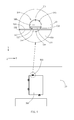
FIG. 1 illustrates a design on the back plate of a conventional laptop computer. As shown in FIG. 1, the back plate 10 of the laptop computer 1 is formed with an opening 13. Users or engineers can access and replace components inside the laptop computer 1 through the opening 13. The cover 30 covers the opening 13 to protect components inside the back plate 10 from damage caused by the external force. As shown in FIG. 1, the cover 30 is conventionally screwed to the back plate 10 on the periphery around the opening 13 by means of screws 50 to cover the opening 13. When replacing the internal component, the user must release the screws 50 with a screw driver or other suitable tool so as to detach the cover 30. Similarly, when the replacement of component is achieved, the tool is again used to lock the screws 50. Such a design is inconvenient in use since the use of additional tool is required, and moreover, the screws 50 are likely lost so that the cover 30 cannot be screwed back.
SUMMARY OF THE INVENTION
An object of the present invention is to provide an electronic device with an easy detachable cover plate.
Another object of the present invention is to provide an electronic device with improved positioning effect on the detachable cover plate.
The electronic device includes a housing, a cover plate, and a button. The housing includes a housing plate formed with an opening, wherein the opening is encompassed by an edge of the housing plate. The cover plate is separably disposed on the housing plate and correspondingly covers the opening. A groove is formed on an edge of the cover plate. In addition to the top opening of the groove, the groove has a further opening formed on the edge of the cover plate.
The button pivotally connects to the edge of the housing which encompasses the opening. The button can rotate on the plane of the housing plate and correspond to the groove of the cover plate. The button has a long arm portion and a short arm portion disposed on two opposite ends. A distance between the edge of the long arm portion and the rotation center of the button is longer than a distance between the edge of the short arm portion and the rotation center.
The button can rotate between a release position and a lock position. When the button rotates to the release position, the short arm portion faces the opening. The long arm portion is behind the short arm portion and retreats behind the edge of the housing plate. In this configuration, the button and the cover plate do not interfere with each other so that the cover plate can be freely separated from the housing plate. When the button rotates to the lock position, the long arm portion of the button extends out the edge of the housing plate and into the groove of the cover plate. In this configuration, the long arm portion interferes with the cover plate, so that the cover plate cannot be separated from the housing plate along a direction perpendicular to the housing plate, i.e. Z direction.
BRIEF DESCRIPTION OF THE DRAWINGS
FIG. 1 illustrates a schematic view of a conventional electronic device;
FIG. 2 illustrates a schematic view of an electronic device in accordance with one embodiment of the present invention;
FIG. 3 is a schematic view of an embodiment of the cover plate;
FIG. 4 is a schematic view of an embodiment showing the button in the release position;
FIG. 5 a schematic view of an embodiment showing the button in the lock position;
FIG. 6A is a schematic view of an embodiment of the button;
FIG. 6B is a schematic view of the button touching the working surface;
FIG. 7A is a side view of an embodiment of the button;
FIG. 7B is a schematic view of an embodiment showing the combination of the button and the second recess;
FIG. 7C is a schematic view of the groove and the sub-groove in accordance with one embodiment;
FIG. 8A is a schematic cross-sectional view of an embodiment showing the button in the release position;
FIG. 8B is a schematic cross-sectional view of an embodiment showing the button in the lock position;
FIG. 9A is a schematic view of an embodiment showing the support plate provided with breaches;
FIG. 9B is a schematic view of an embodiment showing the protruding part engaged with the breach; and
FIG. 10 is a schematic view of an embodiment showing the button disposed on the cover plate.
DETAILED DESCRIPTION OF THE PREFERRED EMBODIMENT
The present invention provides an electronic device and a housing structure thereof. In a preferred embodiment, the electronic device includes a laptop computer; however, in different embodiments, the electronic device may include the personal computer, the electronic reader, the mobile communication device, the video and audio devices, or other types of electronic devices.
In the embodiment of FIG. 2, the electronic device includes a housing 100, a cover plate 300, and a button 500. The housing 100 has a housing plate 110. In this embodiment, the housing plate 110 is on the bottom of the housing 100 to serve as a back plate. However, in other embodiments, the housing plate 110 can be a side plate or even a front plate of the housing 100. The housing plate 110 is formed with an opening 130. The opening 130 is encompassed by an edge 150 of the housing plate 110. As shown in FIG. 2, the opening 130 is preferably formed in rectangular. However, in different embodiments, the opening 130 can be formed in circular or other shape as appropriate.
As shown in FIG. 2, the cover plate 300 is separably disposed on the housing plate 110 and correspondingly covers the opening 130. In this embodiment, the cover plate 300 and the opening 130 have the same shape to completely cover the opening 130. Moreover, the lower portion of the edge 150 of the housing plate 110 encompassing the opening 130 extends inwardly into the opening 130 to form a support plate 170. The edge 350 of the cover plate 300 is placed on the support plate 170 and supported by the support plate 170 from falling into the opening 130. Moreover, the edge 350 of the cover plate 300 can be encompassed by the upper portion of the edge 150 of the housing plate 110 so that the top face of the cover plate 300 and the top face of the housing plate 110 are preferably coplanar. The edge 350 of the cover plate 300 and the edge 150 of the housing plate 110 are preferably most closely adjacent, i.e. substantially without a gap; however, in consideration of manufacture tolerance, a slight gap is allowed to exist.
As shown in FIG. 2 and FIG. 3, a groove 330 is formed on the edge 350 of the cover plate 300. In this embodiment, the groove 330 is a half-moon-shaped groove with a bottom which is recessed from the top face of the cover plate 300. In other words, the groove 330 is formed from the top face but not penetrating through the cover plate 300. In addition to the opening on the top face, the groove 330 also has an opening on the edge 350 of the cover plate 330 to correspond to the edge 150 of the housing plate 110. A first engaging part 710 is formed on the sidewall of the groove 330 in a direction parallel to the housing plate 110. In the embodiment of FIG. 3, the first engaging part 710 is an engaging hole which extends along the tangential direction of the arch side of the groove 330 and communicates with the groove 330. However, in different embodiments, the first engaging part 710 can be a hook extending from the sidewall of the groove 330 towards the groove 330 or other positioning mechanism as appropriate.
In the embodiment of FIG. 2 and FIG. 4, the button 500 pivotally connects to the edge 150 of the housing plate 110, which encompasses the opening 130. The button 500 can rotate on the plane of the housing plate 110 and correspond to the position of the groove 330 of the cover plate 300. The button 500 has a long arm portion 501 and a short arm portion 503 distributed on two opposite ends. A distance between the outer edge of the long arm portion 501 and the rotation center of the button 500 is preferably greater than a distance between the rotation center of the button 500 and the edge 150 of the housing plate 110. A distance between the outer edge of the short arm portion 503 and the rotation center of the button 500 is preferably less than the rotation center of the button 500 and the edge 150 of the housing plate 110. In this embodiment, the button 500 is formed as a half-moon-shaped plate with a curve side 505 and a chord side 507. However, in different embodiments, the button 500 can be formed in other shape such as oval shape or triangular shape, instead of half-moon shape.
As shown in FIG. 4, the chord side 507 connects two ends of the curve side 505 and forms a straight line. From other aspect, the half-moon-shaped plate can be formed by cutting a portion from a circular plate. The remaining portion of the circumference is the curve side 505, and the cut line is the chord side 507. In this embodiment, the cut-off portion has an area smaller than that of the remaining half-moon-shaped plate. Therefore, a central angle passing two ends of the curve side 505 of the half-moon-shaped plate is greater than 180°. Furthermore, the rotation center of the button 500 is defined on the center of curvature of the curve side 505, so that each point on the curve side 505 has a same path during rotation.
As show in FIG. 4, in this embodiment, the curve side 505 of the half-moon-shaped plate is the long arm portion 501 and the chord side 507 is the short arm portion 503. Moreover, the long arm portion 501 is formed with a second engaging part 720 in the direction parallel to the housing plate 110. The second engaging part 720 corresponds to the first engaging part 710. In the embodiment of FIG. 4, the second engaging part 720 is a hook protruding from one end of the curve side 505 along the tangential direction. However, in different embodiments, in the situation of corresponding to the first engaging part 710, the second engaging part 720 can be an engaging hole on one end of the curve side 505 recessed along the curve side 505 inwardly towards the button 500. Furthermore, in this embodiment, the second engaging parts 720 are formed on two ends of the curve side 505. Therefore, when the first engaging part 710 on the cover plate 300 has a direction change, the button 500 can rotate in different direction to engage the first engaging part 710 with the second engaging part 720 on different end.
The button 500 horizontally rotates between a release position 210 and a lock position 230 with respect to the cover plate 300. When the button 500 is in the release position 210 as shown in FIG. 4, the short arm portion 503 of the button 500 faces the opening 130, while the long arm portion 501 is behind the short arm portion 503 and retreats behind the edge 150 of the housing plate 110. In this configuration, the button 500 and the cover plate 300 do not interfere with each other, so that the cover plate 300 can be freely separated from the housing plate 110. When the button 500 rotates to the lock position 230, as shown in FIG. 5, the long arm portion 501 of the button 500 extends out the edge 150 of the housing plate 110 and into the groove 300 of the edge 350 of the cover plate 300. In this configuration, the long arm portion 501 will interfere with the cover plate 300, so that the cover plate 300 cannot be separated from the housing plate 110 along a direction perpendicular to the housing plate 110, i.e. Z direction.
Furthermore, the second engaging part 720 of the button 500 is inserted into the first engaging part 710 which is formed as an engaging hole, so that the first engaging part 710 and the second engaging part 720 are engaged with each other. Due to this engagement, the cover plate 300 and the housing plate 110 are restricted to move relative to each other horizontally on the XY plane of the housing plate 110. As described above, due to the production and assembly requirements, the cover plate 300 and the housing plate 110 are designed with a gap therebetween to resolve the manufacture tolerance. Therefore, the engagement relationship between the first engaging part 710 and the second engaging part 720 can prevent the cover plate 300 and the housing plate 110 from moving relative to each other due to the gap.
As shown in FIG. 6A, a spacer 400 protrudes from the top face 510 of the button 500. When the housing 100 is placed on the working surface 600, as shown in FIG. 6B, the surface of the housing plate 110 and the top face 510 of the button 500 will face the working surface 600. At this point, the spacer 400 serves as a foot pad which contacts the working surface 600. With the disposition of the spacer 400, a gap exits between the housing plate 110 and the working surface 600 to allow air flow therethrough to facilitate heat dissipation and to reduce the occurrence of scratches on the housing plate 110 and the cover plate 300 due to the friction with the working surface 600. In this embodiment, the spacer 400 is formed as a protruding ridge and disposed across the surface of the button 500. Since the top face of the button 500 is formed as a portion of a circle, the spacer 400 extends parallel to the diameter direction of the button 500. When intending to rotate the button 500, a force can be conveniently exerted on the ridge-form spacer 400. However, in different embodiments, the spacer 400 can be formed in columnar shape or other shapes with the foot pad effect. Moreover, in a different embodiment, the button 500 may not have the spacer 400. In this case, the force can be exerted on the edge of the short arm portion 503 to rotate the button 500.
In the embodiment of FIG. 7A, the button 500 includes a first plate 530, a second plate 540, and a pivot 550. The first plate 530 and the second plate 540 are preferably parallel to each other. Two ends of the pivot 550 are connected to the inner faces of the first plate 530 and the second plate 540, respectively. The first plate 530 and the second plate 540 can pass through the housing plate 110 to connect with each other by means of the pivot 550. In this embodiment, the first plate 530 and the second plate 540 have the same shape and both are formed with the short arm portion 503 and the long arm portion 501. As shown in FIG. 7B, the housing plate 110 has an upper face and a lower face on the edge 150 around the opening 130 correspondingly to form a first recess 151 and a second recess 153. The first recess 151 and the second recess 153 both have openings on the edge 150 to face the cover plate 300, and a first separator 610 is disposed between the first recess 151 and the second recess 153. The first separator 610 is formed with a pivot hole 611 to communicate the first recess 151 with the second recess 153. When the button 500 pivotally connects the housing plate 110, the pivot 550 can be rotatably accommodated in the pivot hole 611, and the first plate 530 and the second plate 540 are accommodated in the first recess 151 and the second recess 153, respectively. As shown in FIG. 7B, the pivot hole 611 communicates with the edge face of the edge 150 of the housing plate 110 via a connecting slot 613, so that the pivot 550 is engaged into the pivot hole 611 through the connecting slot 613.
As shown in FIG. 7C, the cover plate 300 has a top face 301 and a bottom face 303 opposite to each other. The groove 330 is formed on the top face 301 of the cover plate 300 while a sub-groove 331 opposite to the groove 330 is formed on the bottom face 303. The groove 330 and the sub-groove 331 form openings on the edge face of the edge 350 of the cover plate 300 and communicate with or correspond to the first recess 151 and the second recess 153 of the housing plate 110, respectively. As shown in FIG. 8A, when the button 500 is in the release position 210, the first plate 530 and the second plate 540 are fully accommodated in the first recess 151 and the second recess 153 of the housing plate 110 and do not extend into the groove 330 and the sub-groove 331 of the cover plate 300. As shown in FIG. 8B, when the button 500 is in the lock position 230, the long arm portions 501 of the first plate 530 and the second plate 540 extend out of the first recess 151 and the second recess 153 and are received in the groove 330 and the sub-groove 331 of the cover plate 300. At this point, the cover plate 300 is located between the first plate 530 and the second plate 540.
Specifically, as shown in FIG. 8B, a second separator 620 is disposed between the groove 330 and the sub-groove 331. When the button 500 rotates to the lock position 230, the second separator 620 is located between the first plate 530 and the second plate 540 and clamped by the first plate 530 and the second plate 540. With such a design, the housing plate 110 and the cover plate 300 are firmly positioned on relative positions in the direction perpendicular to the housing plate 110.
In the embodiment of FIG. 9A and FIG. 9B, the support plate 170 on the edge 150 of the housing plate 110 is formed with at least one breach 171. The bottom edge of the cover plate 300 is formed with a protruding part 370 outwardly extending from the cover plate 300 and corresponding to the breach 171. When the cover plate 300 is assembled with the housing plate 110, as shown in FIG. 9B, the protruding part 370 extends into the breach 171 of the support plate 170 to serve as a single-sided positioning device. Then, the button 500 rotates to the lock position 230 to further relatively position the cover plate 300 and the housing plate 110. In the embodiment of FIG. 9A and FIG. 9B, if the edge 150 of the housing plate 110 is disposed with the breach 171 on one side, then the button 500 is not necessary required on this side.
FIG. 10 is another embodiment of the electronic device. Compared to the previous embodiment, in this embodiment, the button 500 is pivotally connected to the cover plate 300 and the groove 330 is disposed on the edge 150 of the housing plate 110. Therefore, when the button 500 is in the release position, the long arm portion 501 retreats behind the edge 350 of the cover plate 300, and the short arm portion 503 faces outside the cover plate 300. When the button 500 rotates to the lock position, the long arm portion 501 extends out the edge 350 of the cover plate 300 and into the groove 330 of the housing plate 110. Furthermore, the positions of the foresaid sub-groove 310, the first recess 151, and the second recess 153 are correspondingly changed.
The present invention has been described through the relevant embodiments above; however, the embodiments above are only exemplary. What needs to point out is that the embodiments disclosed are not intended to limit the scope of the present invention. Contrarily, the modifications and the equivalents included in the spirit and scope of the claims are all included in the scope of this invention.

Claims (19)

What is claimed is:
1. An electronic device, comprising:
a housing having a housing plate with an opening, wherein a portion of an edge of the housing plate encompassing the opening extends inwardly to the opening to form a support plate and the support plate is formed with at least one breach;
a cover plate separably disposed on the housing plate and correspondingly covering the opening, wherein the cover plate is supported by the support plate and has a groove formed on an edge of the cover plate, the groove has a groove bottom surface recessed from and parallel to a surface of the cover plate; and
a button disposed at a different side on the edge of the opening with respect to the groove and rotating on the housing plate between a release position and a lock position, the button comprising a pivot, a first plate and a second plate, the pivot connecting the first plate and the second plate, wherein when the button rotates to the lock position, a portion of the button extends into the groove covering and at least a portion of the groove bottom surface is clamped between the first plate and the second plate such that the button relatively positions the cover plate and the housing plate.
2. The electronic device of claim 1, wherein the button further comprises a spacer, and when the housing is placed on a working surface, the spacer serves as a foot pad contacting the working surface such that a gap exists between the housing plate and the working surface to allow air flowing therethrough to facilitate heat dissipation and to reduce the occurrence of scratches on the housing plate and the cover plate due to friction with the working surface.
3. The electronic device of claim 2, wherein the spacer is formed as a protruding ridge on the surface of the button.
4. The electronic device of claim 1, wherein the button is a half-moon-shaped plate having a curve side and a chord side connecting two ends of the curve side.
5. The electronic device of claim 1, wherein a sidewall of the groove is formed with a first engaging part, and the button has a second engaging part, and wherein when the button rotates to the lock position, the first engaging part is engaged with the second engaging part, and when the button rotates to the release position, the first engaging part and the second engaging part are separated from each other.
6. The electronic device of claim 5, wherein the first engaging part is an engaging hole on the sidewall of the groove, and the second engaging part is a hook, and wherein when the button rotates to the lock position, the hook is inserted into the engaging hole.
7. The electronic device of claim 5, wherein the first engaging part is a hook protruding from the sidewall of the groove, and the second engaging part is a recessed hole, and wherein when the button rotates to the lock position, the hook is inserted into the recessed hole.
8. The electronic device of claim 1, wherein the housing plate has a first recess and a second recess on two surfaces of the edge encompassing the opening, and the first plate and the second plate are rotatably accommodated in the first recess and the second recess, respectively.
9. The electronic device of claim 8, wherein the first plate and the second plate pass through the housing plate connected by the pivot.
10. The electronic device of claim 8, wherein the cover plate has a top surface and a bottom surface opposite to each other, the groove is formed on the top surface of the cover plate, the bottom surface is formed with a sub-groove opposite to the groove, the groove corresponds to the first recess of housing plate, and the sub-groove corresponds to the second recess.
11. The electronic device of claim 10, wherein when the button rotates to the lock position, the cover plate is located between the first plate and the second plate.
12. An electronic device, comprising:
a housing having a housing plate with an opening, wherein a portion of an edge of the housing plate encompassing the opening extends inwardly to the opening to form a support plate, and the housing plate has a groove formed on the edge encompassing the opening, the groove has a groove bottom surface recessed from and parallel to a surface of the housing plate;
a cover plate separably disposed on the housing plate and correspondingly covering the opening, wherein the cover plate is supported by the support plate; and
a button disposed at a different side on the edge of the opening with respect to the groove and rotating between a release position and a lock position, the button comprising a pivot, a first late and a second plate, the pivot connecting the first plate and the second plate, wherein when the button rotates to the lock position, a portion of the button extends into the groove and at least a portion of the groove bottom surface is clamped between the first plate and the second plate;
wherein a first engaging part is formed on a sidewall of the groove, and the button has a second engaging part; the first engaging part is one of a hook and an engaging hole while the second engaging part is the other one of the hook and the engaging hole, when the button rotates to the lock position, the hook is engaged with the engaging hole such that the button cooperate to relatively positions the cover plate and the housing plate; and when the button rotates to the release position, the hook is separated from the engaging hole such that the cover plate and the housing plate may be separated from each other.
13. The electronic device of claim 12, wherein the button further comprises a spacer, and when the housing is placed on a working surface, the spacer serves as a foot pad contacting the working surface such that a gap exists between the housing plate and the working surface to allow air flowing therethrough to facilitate heat dissipation and to reduce the occurrence of scratches on the housing plate and the cover plate due to friction with the working surface.
14. The electronic device of claim 13, wherein the spacer is formed as a protruding ridge on the surface of the button.
15. The electronic device of claim 12, wherein the button is a half-moon-shaped plate having a curve side and a chord side connecting two ends of the curve side.
16. The electronic device of claim 12, wherein the cover plate has a first recess and a second recess on two opposite surfaces, and the first plate and the second plate are rotatably accommodated in or extend from the first recess and the second recess, respectively.
17. The electronic device of claim 16, wherein the first plate and the second plate pass through the cover plate connected by the pivot.
18. The electronic device of claim 16, wherein the housing plate has a top surface and a bottom surface opposite to each other, the groove is formed on the top surface of the housing plate, the bottom surface is formed with a sub-groove opposite to the groove, the groove corresponds to the first recess of the cover plate, and the sub-groove corresponds to the second recess of the cover plate.
19. The electronic device of claim 18, wherein when the button rotates to the lock position, the housing plate is located between the first plate and the second plate.
US12/821,240 2009-10-23 2010-06-23 Electronic device with cover plate Active 2031-12-26 US8854811B2 (en)

Applications Claiming Priority (3)

Application Number Priority Date Filing Date Title
TW98136048A 2009-10-23
TW98136048A TWI403249B (en) 2009-10-23 2009-10-23 Electronic device with cover plate
TW098136048 2009-10-23

Publications (2)

Publication Number Publication Date
US20110094766A1 US20110094766A1 (en) 2011-04-28
US8854811B2 true US8854811B2 (en) 2014-10-07

Family

ID=43897423

Family Applications (1)

Application Number Title Priority Date Filing Date
US12/821,240 Active 2031-12-26 US8854811B2 (en) 2009-10-23 2010-06-23 Electronic device with cover plate

Country Status (2)

Country Link
US (1) US8854811B2 (en)
TW (1) TWI403249B (en)

Cited By (2)

* Cited by examiner, † Cited by third party
Publication number Priority date Publication date Assignee Title
US20140313667A1 (en) * 2013-04-22 2014-10-23 Hon Hai Precision Industry Co., Ltd. Electronic device with fan module
US10178783B2 (en) * 2015-05-15 2019-01-08 Nec Platforms, Ltd. Display device

Families Citing this family (4)

* Cited by examiner, † Cited by third party
Publication number Priority date Publication date Assignee Title
CN110399016B (en) * 2018-04-24 2024-01-23 光宝电子(广州)有限公司 Casing structure
CN111432591A (en) * 2019-01-10 2020-07-17 杭州疆域创新医疗科技有限公司 Electronic device and ejecting mechanism thereof
CN110505774B (en) * 2019-06-04 2021-10-22 上海浦江桥隧运营管理有限公司 Pier safety inspection surface of water controlling means
WO2024025557A1 (en) * 2022-07-29 2024-02-01 Hewlett-Packard Development Company, L.P. Removable hinge caps

Citations (17)

* Cited by examiner, † Cited by third party
Publication number Priority date Publication date Assignee Title
US5955700A (en) * 1997-12-30 1999-09-21 Motorola, Inc. Housing unit including a latching mechanism with a cam
US6043977A (en) * 1996-10-21 2000-03-28 Kabushiki Kaisha Toshiba Information processing apparatus having a receptacle for removably containing a functional component
CN2400818Y (en) 1999-10-18 2000-10-11 神基科技股份有限公司 Rotary fixing structure
TWM244495U (en) 2003-06-10 2004-09-21 Inventec Corp Structure of magnetic switch module
CN2643604Y (en) 2003-07-30 2004-09-22 志合电脑股份有限公司 Casing structure for portable electronic device
US20050045415A1 (en) 2003-08-27 2005-03-03 Ian Popken Flush mountable vibration reducing loudspeaker mounting assembly
US6929291B2 (en) * 2003-07-28 2005-08-16 Inventec Corp. Magnetic lock
US20060007647A1 (en) * 2004-07-09 2006-01-12 Mitac Technology Corporation Lid mechanism for an interface slot opening of notebook computers
US20060050474A1 (en) * 2004-09-08 2006-03-09 Hiroyuki Kusaka Computer with restriction feature for restricting user access
US20060154136A1 (en) * 2005-01-07 2006-07-13 Fih Co.,Ltd Battery cover latching assembly for portable electronic device
US7303424B2 (en) * 2006-01-14 2007-12-04 Shenzhen Futaihong Precision Industry Co., Ltd. Battery cover assembly for portable electronic device
US20080074834A1 (en) * 2006-05-19 2008-03-27 First International Computer, Inc. Rereconfigurable structure for panel of portable personal computer
US20090290958A1 (en) * 2008-05-26 2009-11-26 Foxnum Technology Co., Ltd. Electronic device and fixture for same
US20100014221A1 (en) * 2008-07-15 2010-01-21 Shenzhen Futaihong Precision Industry Co., Ltd. Battery cover assembly for portable electronic device
US20100085691A1 (en) * 2008-10-02 2010-04-08 Wistron Corporation Housing for an electronic device
US8079561B2 (en) * 2008-08-26 2011-12-20 Orbit Industries, Inc. Universal metal stud clip
US8424926B2 (en) * 2008-06-02 2013-04-23 Casio Hitachi Mobile Communications Co., Ltd. Mobile telephone

Patent Citations (19)

* Cited by examiner, † Cited by third party
Publication number Priority date Publication date Assignee Title
US6043977A (en) * 1996-10-21 2000-03-28 Kabushiki Kaisha Toshiba Information processing apparatus having a receptacle for removably containing a functional component
US5955700A (en) * 1997-12-30 1999-09-21 Motorola, Inc. Housing unit including a latching mechanism with a cam
CN2400818Y (en) 1999-10-18 2000-10-11 神基科技股份有限公司 Rotary fixing structure
TWM244495U (en) 2003-06-10 2004-09-21 Inventec Corp Structure of magnetic switch module
US6929291B2 (en) * 2003-07-28 2005-08-16 Inventec Corp. Magnetic lock
CN2643604Y (en) 2003-07-30 2004-09-22 志合电脑股份有限公司 Casing structure for portable electronic device
US20050045415A1 (en) 2003-08-27 2005-03-03 Ian Popken Flush mountable vibration reducing loudspeaker mounting assembly
TW200602843A (en) 2004-07-09 2006-01-16 Mitac Technology Corp Cover mechanism for interface slot surface in notebook
US20060007647A1 (en) * 2004-07-09 2006-01-12 Mitac Technology Corporation Lid mechanism for an interface slot opening of notebook computers
US20060050474A1 (en) * 2004-09-08 2006-03-09 Hiroyuki Kusaka Computer with restriction feature for restricting user access
US20060154136A1 (en) * 2005-01-07 2006-07-13 Fih Co.,Ltd Battery cover latching assembly for portable electronic device
US7927730B2 (en) * 2005-01-07 2011-04-19 Shenzhen Futaihong Precision Industry Co., Ltd. Battery cover latching assembly for portable electronic device
US7303424B2 (en) * 2006-01-14 2007-12-04 Shenzhen Futaihong Precision Industry Co., Ltd. Battery cover assembly for portable electronic device
US20080074834A1 (en) * 2006-05-19 2008-03-27 First International Computer, Inc. Rereconfigurable structure for panel of portable personal computer
US20090290958A1 (en) * 2008-05-26 2009-11-26 Foxnum Technology Co., Ltd. Electronic device and fixture for same
US8424926B2 (en) * 2008-06-02 2013-04-23 Casio Hitachi Mobile Communications Co., Ltd. Mobile telephone
US20100014221A1 (en) * 2008-07-15 2010-01-21 Shenzhen Futaihong Precision Industry Co., Ltd. Battery cover assembly for portable electronic device
US8079561B2 (en) * 2008-08-26 2011-12-20 Orbit Industries, Inc. Universal metal stud clip
US20100085691A1 (en) * 2008-10-02 2010-04-08 Wistron Corporation Housing for an electronic device

Cited By (2)

* Cited by examiner, † Cited by third party
Publication number Priority date Publication date Assignee Title
US20140313667A1 (en) * 2013-04-22 2014-10-23 Hon Hai Precision Industry Co., Ltd. Electronic device with fan module
US10178783B2 (en) * 2015-05-15 2019-01-08 Nec Platforms, Ltd. Display device

Also Published As

Publication number Publication date
US20110094766A1 (en) 2011-04-28
TWI403249B (en) 2013-07-21
TW201116190A (en) 2011-05-01

Similar Documents

Publication Publication Date Title
US8854811B2 (en) Electronic device with cover plate
US7536749B2 (en) Hinge assembly having limiting and positioning abilities
TWI479752B (en) Connector mechanism
CN200990036Y (en) Data access device fixing device
US8238090B2 (en) Electronic device
US7379292B2 (en) Electronic device
US20110073445A1 (en) Control mechanism and electronic device using the same
TW200819954A (en) Chassis design for computer systems
US20070169316A1 (en) Hinge with a positioning and limiting assembly
EP4180677A1 (en) Rotary shaft mechanism and electronic device
US8625276B2 (en) Electronic device with airflow guiding duct
AU2017217024B2 (en) Electronic device
CN101725626B (en) Hinge structure
US20120257350A1 (en) Battery ejection system for a portable computer
TWI502326B (en) Door device and storage equipment
US10561042B2 (en) Fluid guiding cover
JP4018093B2 (en) Hinge mechanism
US20070169315A1 (en) Hinge with a positioning and limiting assembly
US20110047755A1 (en) Hinge
US8514555B2 (en) Electronic device
TWI462405B (en) Connector mechanism and related electronic device
TW202112205A (en) Fixing cage
US8081440B2 (en) Portable computer and hinge mechanism thereof
TWM574376U (en) Casing and electronic device
US20230230778A1 (en) Receiving case and chassis having the same

Legal Events

Date Code Title Description
AS Assignment

Owner name: WISTRON CORP., TAIWAN

Free format text: ASSIGNMENT OF ASSIGNORS INTEREST;ASSIGNORS:CHENG, WEN-CHIEH;LEE, YAO-TING;REEL/FRAME:024633/0496

Effective date: 20100609

STCF Information on status: patent grant

Free format text: PATENTED CASE

MAFP Maintenance fee payment

Free format text: PAYMENT OF MAINTENANCE FEE, 4TH YEAR, LARGE ENTITY (ORIGINAL EVENT CODE: M1551)

Year of fee payment: 4

MAFP Maintenance fee payment

Free format text: PAYMENT OF MAINTENANCE FEE, 8TH YEAR, LARGE ENTITY (ORIGINAL EVENT CODE: M1552); ENTITY STATUS OF PATENT OWNER: LARGE ENTITY

Year of fee payment: 8