US8854444B2 - Information processing apparatus and capsule endoscope system - Google Patents
Information processing apparatus and capsule endoscope system Download PDFInfo
- Publication number
- US8854444B2 US8854444B2 US13/433,877 US201213433877A US8854444B2 US 8854444 B2 US8854444 B2 US 8854444B2 US 201213433877 A US201213433877 A US 201213433877A US 8854444 B2 US8854444 B2 US 8854444B2
- Authority
- US
- United States
- Prior art keywords
- vivo
- vivo images
- capsule endoscope
- track
- sequence
- Prior art date
- Legal status (The legal status is an assumption and is not a legal conclusion. Google has not performed a legal analysis and makes no representation as to the accuracy of the status listed.)
- Active
Links
Images


Classifications
-
- A—HUMAN NECESSITIES
- A61—MEDICAL OR VETERINARY SCIENCE; HYGIENE
- A61B—DIAGNOSIS; SURGERY; IDENTIFICATION
- A61B1/00—Instruments for performing medical examinations of the interior of cavities or tubes of the body by visual or photographical inspection, e.g. endoscopes; Illuminating arrangements therefor
- A61B1/04—Instruments for performing medical examinations of the interior of cavities or tubes of the body by visual or photographical inspection, e.g. endoscopes; Illuminating arrangements therefor combined with photographic or television appliances
- A61B1/041—Capsule endoscopes for imaging
-
- A—HUMAN NECESSITIES
- A61—MEDICAL OR VETERINARY SCIENCE; HYGIENE
- A61B—DIAGNOSIS; SURGERY; IDENTIFICATION
- A61B1/00—Instruments for performing medical examinations of the interior of cavities or tubes of the body by visual or photographical inspection, e.g. endoscopes; Illuminating arrangements therefor
- A61B1/00002—Operational features of endoscopes
- A61B1/00004—Operational features of endoscopes characterised by electronic signal processing
- A61B1/00009—Operational features of endoscopes characterised by electronic signal processing of image signals during a use of endoscope
- A61B1/000094—Operational features of endoscopes characterised by electronic signal processing of image signals during a use of endoscope extracting biological structures
-
- A—HUMAN NECESSITIES
- A61—MEDICAL OR VETERINARY SCIENCE; HYGIENE
- A61B—DIAGNOSIS; SURGERY; IDENTIFICATION
- A61B1/00—Instruments for performing medical examinations of the interior of cavities or tubes of the body by visual or photographical inspection, e.g. endoscopes; Illuminating arrangements therefor
- A61B1/00002—Operational features of endoscopes
- A61B1/00043—Operational features of endoscopes provided with output arrangements
- A61B1/00045—Display arrangement
- A61B1/0005—Display arrangement combining images e.g. side-by-side, superimposed or tiled
-
- A—HUMAN NECESSITIES
- A61—MEDICAL OR VETERINARY SCIENCE; HYGIENE
- A61B—DIAGNOSIS; SURGERY; IDENTIFICATION
- A61B5/00—Measuring for diagnostic purposes; Identification of persons
- A61B5/06—Devices, other than using radiation, for detecting or locating foreign bodies ; determining position of probes within or on the body of the patient
Definitions
- the present invention relates to an image processing apparatus that displays in-vivo images obtained by a capsule endoscope inserted to an inside of a subject and a capsule endoscope system.
- an information processing apparatus that performs an image process on data of a group of in-vivo images which are obtained from a capsule endoscope that captures in-vivo images of a subject via a receiver that performs a wireless communication with the capsule endoscope and sorted in an imaging time sequence, includes: a storage unit that stores the data of the in-vivo images and information which is associated with the data of the in-vivo images and related to a position of the capsule endoscope in an inside of the subject; a positional information obtaining unit that obtains positional information of the capsule endoscope in capturing the in-vivo images based on the information related to the position; and a sequence changing unit that changes a sorting sequence of the in-vivo images based on the positional information obtained by the positional information obtaining unit.
- a capsule endoscope system includes: a capsule endoscope that is inserted to an inside of a subject, performs imaging, and generates in-vivo image data which shows in-vivo images of the subject; a receiver that receives the in-vivo image data generated by the capsule endoscope via a wireless communication; and an information processing apparatus that performs an image process on the data of a group of the in-vivo images which are obtained from the capsule endoscope via the receiver and sorted in an imaging time sequence, the information processing apparatus including a storage unit that stores the in-vivo image data and information which is associated with the in-vivo image data and related to a position of the capsule endoscope in the inside of the subject, a positional information obtaining unit that obtains positional information of the capsule endoscope in capturing the in-vivo images based on the information related to the position, and a sequence changing unit that changes a sorting sequence of the in-vivo images based on the positional information obtained by the positional information
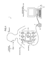
- FIG. 1 is a schematic view of a configuration of a capsule endoscope system according to a first embodiment of the present invention
- FIG. 2 is a schematic view of a configuration of the capsule endoscope shown in FIG. 1 ;
- FIG. 3 is a block diagram of a configuration of the capsule endoscope and a receiver shown in FIG. 1 ;
- FIG. 4 is a block diagram of a configuration of the information processing apparatus shown in FIG. 1 ;
- FIG. 5 is a flowchart showing an operation of the information processing apparatus shown in FIG. 4 ;
- FIG. 6 is a flowchart showing a track calculating process executed by the information processing apparatus shown in FIG. 4 ;
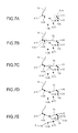
- FIGS. 7A to 7E are explanatory views of the track calculating process
- FIG. 8 is an explanatory view of a method of determining whether or not a detected track is routed through an in-vivo image as a check target;
- FIG. 9 shows a frame format of an example of an interpretation screen displayed in the display unit
- FIG. 10 is a block diagram of a configuration of an information processing apparatus according to a second embodiment of the present invention.
- FIG. 11 is a flowchart showing an operation of the information processing apparatus shown in FIG. 10 ;
- FIG. 12 is a flowchart of a track correcting process executed by the image processing apparatus shown in FIG. 10 ;
- FIGS. 13A to 13C are explanatory views of the track correcting process.
- FIG. 1 is a schematic view of a configuration of a capsule endoscope system according to a first embodiment of the present invention.
- a capsule endoscope system 1 is provided with a capsule endoscope 2 that is inserted to an inside of a subject 10 , captures in-vivo images, and wirelessly transmits data of the in-vivo images to a receiver 3 , the receiver 3 that receives the in-vivo image data wirelessly transmitted from the capsule endoscope 2 , and an information processing apparatus 5 that displays the in-vivo images based on the in-vivo image data received by the receiver 3 .
- the capsule endoscope 2 After being swallowed from a mouth of the subject 10 , the capsule endoscope 2 performs a predetermined signal process with respect to imaging signals obtained by sequentially capturing images of the inside of the subject 10 at predetermined time intervals (at 0.5 second intervals, for example) while traveling an inside of organs of the subject 10 by a peristaltic motion of the organs to generate in-vivo image data.
- the capsule endoscope 2 wirelessly transmits the generated in-vivo image data sequentially to the receiver 3 placed outside whenever capturing in-vivo images of the subject 10 .
- the capsule endoscope 2 is assigned with identification information (a serial number, for example) which allows the capsule endoscope to be identified and the identification information is also wirelessly transmitted together with the in-vivo image data.
- the receiver 3 is provided with an antenna unit 4 including a plurality of receiving antennas 41 a to 41 h .
- the receiving antennas 41 a to 41 h are, for example, realized by using a loop antenna and arranged at predetermined positions on an outside surface of the subject 10 (at positions corresponding to respective organs which are along the traveling route of the capsule endoscope 2 in the inside of the subject 10 , for example).
- the arrangement of the receiving antennas 41 a to 41 h may be changed arbitrarily depending on a purpose of an examination, a diagnosis, and the like.
- the number of antennas provided in the antenna unit 4 is not necessarily limited to eight as shown by the receiving antennas 41 a to 41 h and may be more or less than eight.
- the receiver 3 is carried by the subject 10 and receives the in-vivo image data wirelessly transmitted from the capsule endoscope 2 via the antenna unit 4 while an imaging is performed by the capsule endoscope 2 (while the capsule endoscope 2 , after inserted from a mouth of the subject 10 , travels through the inside of the digestive canal until excreted, for example).
- the receiver 3 stores the received in-vivo image data in an embedded memory.
- the receiver 3 stores, by associating with the in-vivo image data, reception intensity information of each of the receiving antennas 41 a to 41 h at a time of the image reception and time information which indicates a reception time in the memory.
- the reception intensity information and the time information is used in the information processing apparatus 5 as information related to the position of the capsule endoscope 2 .
- the receiver 3 is detached from the subject 10 and connected to the information processing apparatus 5 for the purpose of transferring (downloading) information including the in-vivo image data.
- the information processing apparatus 5 is realized by a workstation or a personal computer provided with a display unit such as a CRT display device and a liquid crystal display device, performs a predetermined process on the in-vivo image obtained via the receiver 3 and position-related information, and displays the in-vivo images in the display unit.
- An operation inputting device 5 b such as a keyset and a mouse is connected to the information processing apparatus 5 .
- a touchscreen overlapped with the display unit may be provided as the operation inputting device 5 b .
- a user While operating the operation inputting device 5 b , a user (interpreter) observes (examines) a biological body site (the esophagus, stomach, small intestine, large intestine, and the like, for example) in the inside of the subject 10 and makes a diagnosis on the subject 10 based on the observation (examination) by interpreting the in-vivo images of the subject 10 sequentially displayed in the information processing apparatus 5 .
- a biological body site the esophagus, stomach, small intestine, large intestine, and the like, for example
- the information processing apparatus 5 is provided with a universal serial bus (USB) port, via which a cradle 5 a is connected.
- the cradle 5 a is a reader that reads the in-vivo image data from the memory of the receiver 3 .
- the receiver 3 is electrically connected to the information processing apparatus 5 and thereby the in-vivo image data and its associated information (reception intensity information, time information, and identification information of the capsule endoscope 2 ) stored in the memory of the receiver 3 is transferred to the information processing apparatus 5 .
- the information processing apparatus 5 obtains a series of in-vivo image data concerning the subject 10 and its associated information in this manner, further performs a process to be explained later, and thus displays the in-vivo images.
- the information processing apparatus 5 may be connected to an output device such as a printer and may output the in-vivo images to the output device.
- the image processing apparatus 5 may obtain the in-vivo image data captured by the capsule endoscope 2 in various methods other than the method explained above.
- a memory such as a USB memory and CompactFlash (registered trademark) which can be detachably attached to the receiver 3 may be used instead of the embedded memory in the receiver 3 .
- the information processing apparatus 5 may be provided with a communication function with an external device and may obtain the in-vivo image data from the receiver 3 via a wire or wireless communication.
- FIG. 2 is a schematic view of an example of a configuration of the capsule endoscope 2 .
- FIG. 3 is a block diagram of a configuration of the capsule endoscope 2 and the receiver 3 .
- the capsule endoscope 2 is housed in a capsule-shaped casing (housing) formed by a casing 2 b which has an approximately cylindrical shape or a semi-elliptical spherical shape and whose one end has a hemispherical dome shape and the other end has an opening; and an optical dome 2 a which has a hemispherical shape and seals an inside of the casing 2 b in a water-tight manner when fitted to the opening of the casing 2 b .
- the capsule-shaped casing ( 2 a , 2 b ) has a size to be swallowed by the subject 10 , for example.
- at least the optical dome 2 a is formed of a transparent material.
- the capsule endoscope 2 is provided with an imaging unit 21 that captures images of the inside of the subject 10 , an illumination unit 22 that illuminates the inside of the subject 10 in the imaging, a circuit board 23 on which respective driving circuits and the like for driving the imaging unit 21 and the illumination unit 22 are formed, a signal processor 24 , a memory 25 , a transmitter 26 , an antenna 27 , and a battery 28 .
- the imaging unit 21 includes an imaging element 21 a such as a CCD and a CMOS that generate data of an in-vivo image of the subject from an optical image formed on a light reception surface and an optical system 21 b such as an objective lens provided at a side of the light reception surface of the imaging element 21 a , for example.
- the illumination unit 22 is realized by a light emitting diode (LED) and the like that emits a light towards the inside of the subject 10 in the imaging.
- the imaging element 21 a , the optical system 21 b , and the illumination unit 22 are mounted on the circuit board 23 .
- the driving circuit of the imaging unit 21 operates under a control of the signal processor 24 to be described later, generates an imaging signal indicating an image of the inside of the subject 10 regularly (two frames per second, for example), and inputs the generated imaging signal to the signal processor 24 .
- the imaging unit 21 and the illumination unit 22 will be explained below on the assumption that respective driving circuits are included.
- the circuit board 23 on which the imaging unit 21 and the illumination unit 22 are mounted is arranged at a side of the optical dome 2 a in the inside of the capsule-shaped casing ( 2 a , 2 b ) in a state where the light reception surface of the imaging element 21 a and a direction of the light emission of the illumination unit 22 are oriented to the inside of the subject 10 via the optical dome 2 a . Therefore, the imaging direction of the imaging unit 21 and the illuminating direction of the illumination unit 22 are oriented to an outside of the capsule endoscope 2 via the optical dome 2 a as shown in FIG. 2 .
- This configuration enables capturing images of the inside of the subject 10 by the imaging unit 21 while illuminating the inside of the subject 10 by the illumination unit 22 .
- the signal processor 24 controls each unit in the capsule endoscope 2 , generates digital in-vivo image data via an A/D conversion of the imaging signal output from the imaging unit 21 , and performs a predetermined signal process.
- the memory 25 temporarily stores various operations to be performed by the signal processor 24 and in-vivo image data to which the signal process is performed by the signal processor 24 .
- the transmitter 26 and the antenna 27 superimpose the in-vivo image data stored in the memory 25 with the identification information of the capsule endoscope 2 on a wireless signal and transmit it to the outside.
- the battery 28 supplies an electric power to each unit in the capsule endoscope 2 .
- the battery 28 is configured to include a power source circuit that raises a voltage of an electric power supplied from a primary battery such as a button battery or a secondary battery.
- the receiver 3 is provided with a receiving unit 31 , a signal processor 32 , a memory 33 , an interface (I/F) unit 34 , an operation unit 35 , a display unit 36 , and a battery 37 .
- the receiving unit 31 receivers the in-vivo image data wirelessly transmitted from the capsule endoscope 2 via the receiving antennas 41 a to 41 h .
- the signal processor 32 controls each unit in the receiver 3 and performs a predetermined signal process on the in-vivo image data received by the receiving unit 31 .
- the memory 33 stores various operations to be performed by the signal processor 32 , and the in-vivo image data to which the signal process is performed by the signal processor 32 and its associated information (reception intensity information, time information, and the like).
- the interface unit 34 transmits the image data stored in the memory 33 to the information processing apparatus 5 through the cradle 5 a .
- the operation unit 35 allows a user to input various operational instructions and settings to the receiver 3 .
- the display unit 36 notifies a user of or displays information of various kinds.
- the battery 37 supplies an electric power to each unit in the receiver 3 .
- FIG. 4 is a block diagram of a configuration of the information processing apparatus 5 .
- the information processing apparatus 5 is provided with an interface (I/F) unit 51 , a temporal storage unit 52 , an image processor 53 , a positional information obtaining unit 54 , a sequence changing unit 55 , a correlation degree calculator 56 , a track calculator 57 , an examination information generator 58 , a storage unit 59 , a display controller 60 , and a display unit 61 .
- I/F interface
- the interface unit 51 accepts the in-vivo image data input through the cradle 5 a and its associated information, and instructions and information of various kinds input via the operation inputting device 5 b.
- the temporal storage unit 52 is realized by a volatile memory such as a DRAM and an SRAM, and temporarily stores the in-vivo image data and its associated information input from the receiver 3 via the interface unit 51 .
- a recording medium such as a hard disk drive (HDD), a magnetooptical (MO) disk, a CD-R, and a DVD-R and a driving device that drives such a recording medium may be provided instead of the temporal storage unit 52 , and the in-vivo image data input from the interface unit 51 may be temporarily stored in the recording medium.
- the image processor 53 performs various kinds of image processes such as a white balance process, a demosaicing, a color conversion, a density conversion (a gamma conversion and the like), a smoothing (a noise elimination and the like), a sharpening (an edge emphasis and the like), and an image recognition with respect to the in-vivo image data stored in the temporal storage unit 52 .
- the image recognition process specifically includes a detection of an image area having a feature of a diseased site such as neoplastic, vascular, and hemorrhagic areas, a discrimination of organs, a calculation of an average color
- the positional information obtaining unit 54 obtains information (positional information) which indicates a positional coordinate of the capsule endoscope 2 in the imaging of each in-vivo image by performing a position estimating process based on the reception intensity information and the time information stored in the temporal storage unit 52 . Specifically, the positional information obtaining unit 54 obtains the reception intensity of each of the receiving antennas 41 a to 41 h from the temporal storage unit 52 , the reception intensity being associated with in-vivo image data received at a given time, and extracts a spherical area whose radius is a distance depending on the reception intensity centering around each of the receiving antennas 41 a to 41 h . Here, the lower the reception intensity becomes, the larger the radius becomes.
- the position where these areas intersect is estimated to be the position of the capsule endoscope 2 at the given time, i.e., the position in the subject 10 (hereinafter referred to as “position of in-vivo image”) where the in-vivo image is captured.
- position of in-vivo image the position in the subject 10
- the obtained positional information is associated with the in-vivo image and the time information and stored in the storage unit 59 .
- the position estimating process is not necessarily required to be performed on all the in-vivo images in time series and may be performed through a sampling in a predetermined density.
- the sequence changing unit 55 changes the sorting sequence of the in-vivo images in the initial imaging time sorting sequence based on the positional information obtained by the positional information obtaining unit 54 and the degree of correlation calculated by the correlation degree calculator 56 to be described later. Specifically, the sequence changing unit 55 changes the sequence so that the series of in-vivo images shows a stream from an upper area to a lower area in the digestive canal by extracting in-vivo images which each is a target on which whether to change the sorting sequence is determined based on the positional information and evaluating the degree of correlation in the in-vivo images according to a predetermined criterion.
- the sequence changing unit 55 is provided with a determining unit 55 a that determines whether or not the capsule endoscope 2 has performed a reciprocatory motion and a specifying unit 55 b that specifies in-vivo images which are determined to be captured redundantly when the reciprocatory motion is determined to be present by the determining unit 55 a.
- the correlation degree calculator 56 calculates the degree of correlation in the in-vivo images which are each treated as the determination target by the sequence changing unit 55 .
- the track calculator 57 calculates a track along which the capsule endoscope 2 has passed during a period after the capsule endoscope 2 is inserted to the inside of the subject 10 and until excreted to the outside by sequentially joining respective positional coordinates of the in-vivo images according to the sorting sequence, changed by the sequence changing unit 55 , of the in-vivo images.
- the examination information generator 58 generates information concerning an appropriate examination based on the information input via the operation inputting device 5 b .
- the information includes patient information (ID, name, sex, age, date of birth, and the like) for identifying the subject 10 as a patient and medical examination information (hospital name, name of a doctor or a nurse who performs an administration of a capsule endoscope, date and time of the capsule administration, date and time when data is obtained, serial number of the capsule endoscope 2 , serial number of the receiver 3 , and the like) for identifying the content of the medical examination for the subject 10 .
- the examination information may be generated in advance before the transmission of the in-vivo image data from the receiver 3 or may be generated after the transmission of the in-vivo image data.
- the storage unit 59 stores, in addition to the various process programs performed by the image processing apparatus 5 , in-vivo image data to which an image process is performed by the image processor 53 , the positional information obtained by the positional information obtaining unit 54 , the track data calculated by the track calculator 57 , the examination information generated by the examination information generator 58 , and the like.
- the storage unit 59 is realized by a recording medium such as a semiconductor memory like a flash memory, a random access memory (RAM), and a read only memory (ROM), a hard disk drive (HDD), a magnetooptical (MO) disk, a CD-R, and a DVD-R and a driving device that drives the recording medium, for example.
- the display controller 60 controls the display unit 61 to display an interpretation screen including the in-vivo images and the track of the capsule endoscope 2 and other information of various kinds in a predetermined format.
- the display unit 61 is realized by a CRT display device and a liquid crystal display device and displays the interpretation screen including the in-vivo images of the subject 10 and information of various kinds under the control by the display controller 60 .
- FIG. 5 is a flowchart showing an operation of the information processing apparatus 5 .
- step S 101 when the receiver 3 is attached to the cradle 5 a (“Yes” at step S 101 ), the transmission of the in-vivo image data and its associated information stored in the memory 33 of the receiver 3 to the image processing apparatus 5 is started (step S 102 ).
- the transmitted in-vivo image data and the like are stored in the temporal storage unit 52 .
- the information processing apparatus 5 waits for the receiver 3 to be attached.
- step S 103 when the transmission of the in-vivo image data and the like is completed (“Yes” at step S 103 ), the image processor 53 performs an image process on the in-vivo image data stored in the temporal storage unit 52 and the positional information obtaining unit 54 obtains the position of each in-vivo image based on the reception intensity information and the time information stored in the temporal storage unit 52 (step S 104 ).
- the in-vivo image data to which the image process is performed and the positional information indicating the position of each in-vivo image is stored in the storage unit 59 .
- step S 105 the image processing apparatus 5 calculates a track while checking respective positional coordinates of the in-vivo images sorted in the imaging time sequence and arbitrarily changing their sorting sequence. This process is repetitively performed as far as an in-vivo image as a check target is present (“Yes” at step S 106 ).
- step S 106 when no more in-vivo image as a check target is present (“No” at step S 106 ), the storage unit 59 stores the track data calculated by the track calculator 57 (step S 107 ).
- step S 108 the display controller 60 reads out the in-vivo image data to which the image process is performed and the track data from the storage unit 59 and controls the display unit 61 to display the interpretation screen. A display example of the interpretation screen will be described later.
- FIG. 6 is a flowchart showing a track calculating process performed by the information processing apparatus 5 .
- FIGS. 7A to 7E are explanatory views of the track calculating process.
- positions of in-vivo images are indicated by points a to h.
- Parenthetic numerals ( 1 ) to ( 8 ) provided to respective points a to h indicate the sorting sequence of the in-vivo images at the respective points a to h.
- the sequence of the reference symbol a to h corresponds to the sorting sequence ( 1 ) to ( 8 ) provided thereto in FIG. 7A .
- FIG. 7A a track T 1 calculated on the way to the point a is shown.
- the sequence changing unit 55 extracts an in-vivo image as a check target and obtains positional information including the positional coordinate of the in-vivo image.
- the order of the extraction of the check target is not specifically limited as long as all check targets are covered.
- the first embodiment is configured to perform the check along the initial sorting sequence from ( 2 ) to ( 8 ), starting from an in-vivo image (at the point b in the sequence 2 ) captured right after the in-vivo image at the point a (in the sequence 1 ) where the track T 1 is already calculated.
- the sequence changing unit 55 checks whether or not an already-checked in-vivo image captured around the in-vivo image as the check target is present. Specifically, whether or not a positional coordinate of an already-checked in-vivo image is present within a predetermined range centering around the positional coordinate of the in-vivo image as the check target (within a cube whose side has a predetermined length or within a sphere having a predetermined radius, for example) is determined.
- the size of the predetermined range (the length of one side of the cube, the radius of the sphere, or the like, for example) may be determined based on an imaging frame rate and an average traveling velocity of the capsule endoscope 2 , for example.
- the size of the predetermined range may be determined based on an accuracy of a positional estimation (a sampling density in which the positional estimating process is performed). For example, when the point b shown in FIG. 7A is checked, no already-checked point is present within a predetermined range A(b). When no already-checked point is present within the predetermined range of the check target point in this situation (“No” at step S 112 ), the operation moves to step S 113 .
- a positional estimation a sampling density in which the positional estimating process is performed.
- the sequence changing unit 55 checks whether or not an already-calculated track is present around the position of the in-vivo image as the check target. Specifically, whether or not a track passes through the predetermined range of the point corresponding to the in-vivo image as the check target is determined. In the case of the point b shown in FIG. 7A for example, no track passing through the predetermined range A(b) is present. When no already-calculated track passing through the predetermined range of the check target point in this situation (“No” at step S 113 ), the operation moves to step S 114 .
- the track calculator 57 calculates a track which joins the position of the in-vivo image as the check target and the position of an in-vivo image present right before the target in-vivo image. As a result, a track T 2 joining the point a and the point b is generated as shown in FIG. 7B .
- step S 112 a process in the case where an already-checked in-vivo image captured around the in-vivo image as the check target is present at step S 112 (“Yes” at step S 112 ) will be explained.
- the point c shown in FIG. 7B is checked, it is found that the point a is included within a predetermined range A(c).
- the correlation degree calculator 56 calculates a degree of correlation between the in-vivo image as the check target and the in-vivo image whose imaging position is determined to be close (in-vivo image as a comparison target) (step S 121 ).
- the degree of correlation known various indexes such as a correlation value in a fixed size block, a traveling amount of a template calculated via a block matching method (magnitude of a vector), and a change rate in brightness between in-vivo images may be used, for example.
- the determining unit 55 a determines whether or not the degree of correlation calculated by the correlation degree calculator 56 is high, i.e., how the capsule endoscope 2 travels in the inside of the subject 10 .
- the degree of correlation between in-vivo images which are close to each other in position is considered to depend on the differences explained in (i) to (iii) below.
- the degree of correlation becomes moderate to high when the capsule endoscope 2 is retained and thereby the traveling distance is short while the motion of the intestine in the subject 10 is working or when the capsule endoscope 2 performs a reciprocatory motion within a certain range and thereby positions comparatively close to each other are captured, for example.
- in-vivo images locate close to each other when positions overlap due to a tortuous shape of the intestine even though different positions in the intestine canal are captured. In this situation, the degree of correlation between the in-vivo images becomes low.
- the degree of correlation between in-vivo images is determined to be high when the degree of correlation is moderate or high, i.e., in the situation (ii) described above and to be low when the degree of correlation is low, i.e., in the situation (iii) described above.
- the sequence changing unit 55 changes the sorting sequence of the in-vivo images based on the positional information of the in-vivo image as the check target, the in-vivo image as the comparison target, and an in-vivo image right before or after the comparison target (step S 123 ).
- the specifying unit 55 b specifies the in-vivo images whose degree of correlation is high as a group of in-vivo images whose imaging positions are close to each other and sets a flag in in-vivo image data so that they can be treated as in-vivo images belonging to the same group.
- the specifying unit 55 b may specify the in-vivo images whose degree of correlation is significantly high as a group of in-vivo images whose imaging positions are the same and set a flag in the in-vivo image data.
- the degree of correlation between the in-vivo images is low (“No” at step S 122 )
- the original sorting sequence remains and the operation moves to step S 114 .
- the sequence changing unit 55 extracts a positional coordinate of a point right before or after the point a (the point b in the case in FIG. 7B ) and changes the sorting sequence of the in-vivo images so that a route passing through these three points becomes the shortest.
- the initial sorting sequence “the point a( 1 ) ⁇ the point b( 2 ) ⁇ the point c( 3 )” is changed to the sequence “the point a( 1 ) ⁇ the point c( 2 ) ⁇ the point b( 3 )” as shown in FIG. 7C .
- the track calculator 57 calculates a track based on the changed sorting sequence.
- the track T 2 joining the point a and the point b is deleted and a track T 3 joining the point a, the point c, and the point b in this order is added.
- step S 113 a process in the case where an already-calculated track is present around the position of the in-vivo image as the check target (“Yes” at step S 113 ) will be explained. For example, when the point d shown in FIG. 7C is checked, it is found that the track T 3 passes through a predetermined range A(d).
- the sequence changing unit 55 determines whether or not the detected track is routed through the position of the in-vivo image as the check target (step S 131 ). This determination is performed by using one of the following methods (i) to (iii), for example.
- an interpolated image is generated based on the in-vivo images at the point c and the point b which are both ends of the detected track T 3 . It is preferable to generate the interpolated image by taking a mutual positional relation between in-vivo images (distance and the like between in-vivo images) into consideration. For example, an interpolated image at a position d′ obtained by projecting the position d onto the track T 3 is generated as shown in FIG. 8 . Then, a degree of similarity between the interpolated image and the in-vivo image at the point d is calculated.
- the degree of similarity various indexes such as a correlation coefficient, a change rate in brightness, and a combination thereof may be used.
- the larger the correlation coefficient is the higher the degree of similarity becomes.
- the lower the change rate in brightness is the higher the degree of similarity becomes.
- An optical flow indicates a travel amount expressed as vector data through an association of the same object (object position) captured at different times in two images.
- known methods such as a block matching and a gradient method are used.
- respective optical flows between the point c and the point d and between the point d and the point b are calculated on the assumption that the point d locates between the point c and the point b, and whether or not the optical flows are smoothly connected to each other is determined.
- the track T 3 is determined to be routed through the point d.
- the track T 3 is determined not to be routed through the point d.
- the block matching is performed between the in-vivo image at the point c and the in-vivo image at the point d and between the in-vivo image at the point d and the in-vivo image at the point b to obtain the number of matching templates.
- the number of matching templates is equal to or more than a predetermined threshold each between the point c and the point d and between the point d and the point b, it is determined that the point d is highly correlated with both of the point c and the point b and the track T 3 is routed through the point d.
- the number of matching templates is less than the predetermined threshold at least one of the relations between the point c and the point d and between the point d and the point b, it is determined that the track T 3 is not routed through point d.
- a summation of correlation coefficients and a maximum value of the correlation coefficients in the block matching may be obtained instead of the number of matching templates, and the values may be compared to a predetermined threshold to determine whether or not the track T 3 is routed through the point d.
- the sequence changing unit 55 changes the sorting sequence of the in-vivo images at both ends of the detected track (step S 132 ).
- the sequence changing unit 55 changes the sorting sequence of the in-vivo images to “the point c( 2 ) ⁇ the point d( 3 ) ⁇ the point b( 4 )” according to the determination.
- the track calculator 57 deletes the track T 3 joining the point c and the point b and adds a track T 4 joining the point c, the point d, and the point b in this order (see FIG. 7D ).
- step S 131 when the detected track is determined not to be routed through the in-vivo image as the check target (“No” at step S 131 ), the original sorting sequence remains and the operation moves to step S 114 .
- steps S 111 to S 114 , S 121 to S 123 , and S 131 to S 132 are further repeated with respect to points e to h while a predetermined range for each check target (a predetermined range A(e) centering around the point e, for example) is set.
- a predetermined range for each check target a predetermined range A(e) centering around the point e, for example
- a total track R is generated as shown in FIG. 7E .
- FIG. 9 shows a frame format of an example of an interpretation screen displayed in the display unit 61 .
- An interpretation screen 100 includes a patient information area 101 in which identification information of the subject 10 as a patient is displayed, a medical examination information area 102 in which identification information of medical examinations performed on the subject 10 is displayed, a main display area 103 in which a series of in-vivo images are reproduced as pseudo moving or still images, a reproducing operation button group 104 which enables an operation of reproducing in-vivo the images displayed in the main display area 103 , a thumbnail area 105 in which a plurality of reduced in-vivo images are displayed as thumbnails, a time bar 106 which indicates a time when the in-vivo image currently displayed in the main display area 103 is obtained, a color bar 107 which indicates an average color of each image in the series of in-vivo images in time series, and a track display area 108 .
- the reduced images in the thumbnail area 105 and points on the time bar 106 indicating respective time points when the reduced images are obtained are displayed by being connected by lines in the screen.
- a display area at each time point on the color bar 107 an average color of an in-vivo image of the subject captured at each time point is indicated.
- the interpreter since each of the series of in-vivo images presents a specific average color depending on the organ captured, it is possible for the interpreter to easily tell the organ shown in an in-vivo image at each time point based on a transition of the average colors along the time axis.
- the track display area 108 the track R calculated by the track calculator 57 is displayed by overlapping with a subject image 110 indicating the subject 10 .
- the display controller 60 thins out and displays a group of in-vivo images whose imaging positions are close to each other and which are specified (flag-set) by the specifying unit 55 b . Or, only one of a group of in-vivo images whose imaging positions are the same may be displayed. In either case, it is possible to make a rate in displaying a pseudo moving in the main display area 103 high. In the case of displaying in-vivo images as still images, it is possible to reduce the number of in-vivo images to be displayed.
- the reduced images which are connected to the time bar 106 by lines and displayed in the thumbnail area 105 are preferable as for the reduced images which are connected to the time bar 106 by lines and displayed in the thumbnail area 105 , too that a group of in-vivo images whose imaging positions are close to each other or the same is thinned out or omitted in displaying.
- a distance bar may be generated based on in-vivo images after the sorting sequence is changed (after the group of in-vivo images whose imaging positions are close to each other or the same is thinned out and the like as appropriate) and may be displayed together with or instead of the color bar 107 on the interpretation screen 100 .
- the distance bar is generated by one-dimensionally presenting average colors of respective in-vivo images along the sorting sequence of the in-vivo images.
- a redundant distance added due to the reciprocatory motion and the like of the capsule endoscope 2 is eliminated. Therefore, it is possible for the interpreter to easily tell the organ shown in each in-vivo image, judging from the transition of the average colors along the corrected track of the capsule endoscope 2 .
- a motion detecting process may be performed between each in-vivo image and its previous in-vivo image in the sorting sequence and the rate in displaying a pseudo moving may be automatically adjusted based on a motion amount (magnitude of motion vector) therebetween. For example, a displaying rate is lowered with respect to an in-vivo image having a large motion amount and heightened with respect to an in-vivo image having a small motion amount, so that interpretation efficiency can be improved.
- the motion detecting process in this case may be performed between in-vivo images whose sorting sequence is not yet changed (i.e., between in-vivo images sorted in the imaging time sequence) or between in-vivo images whose sorting sequence is already changed (i.e., between in-vivo images sorted in the corrected track sequence).
- the first embodiment it becomes possible according to the first embodiment to reduce an influence of a reciprocatory motion and the like of the capsule endoscope 2 and to display in-vivo images along a route from an upper to a lower stream in the digestive canal since the sorting sequence of the in-vivo images is changed based on positional information and degree of correlation of the in-vivo images. Besides, since a track of the capsule endoscope 2 is generated according to the changed sorting sequence, it becomes possible to grasp the position indicated by each in-vivo image in the inside of the subject 10 more accurately.
- orientation information of the capsule endoscope 2 can be obtained by using various known methods including a method of providing a magnet in an eccentrically-located manner with respect to a rotation axis and detecting a magnetic field formed by this magnet, for example.
- a capsule endoscope system according to a second embodiment will be explained next.
- a capsule endoscope system according to the second embodiment is provided with an information processing apparatus 6 shown in FIG. 10 instead of the information processing apparatus 5 shown in FIG. 4 .
- the information processing apparatus 6 is provided with a track calculator 65 , a sequence changing unit 66 , and a correlation degree calculator 67 instead of the sequence changing unit 55 , the correlation degree calculator 56 , and the track calculator 57 shown in FIG. 4 .
- Other components are the same as those shown in FIGS. 1 to 4 .
- the track calculator 65 calculates a track of the capsule endoscope 2 in the inside of the subject 10 based on the positional information obtained by the position information obtaining unit 54 and also corrects the track according to the in-vivo image sorting sequence changed by the sequence changing unit 66 to be described later.
- the sequence changing unit 66 changes the sorting sequence of the in-vivo images in the initial imaging time sorting sequence based on the positional information obtained by the positional information obtaining unit 54 and a degree of correlation calculated by a correlation degree calculator 67 to be described later.
- the correlation degree calculator 67 calculates a degree of correlation between the in-vivo images which are each the determination target on the sorting sequence changed by the sequence changing unit 66 .
- FIG. 11 is a flowchart showing an operation of the information processing apparatus 6 .
- a track is generated tentatively in the initial sorting sequence (i.e., in the sequence of the imaging time of the in-vivo images) and then corrected by checking each of the in-vivo images and arbitrarily changing the sorting sequence.
- the information processing apparatus 6 obtains in-vivo image data and its associated information from the receiver 3 and obtains the positional information of the in-vivo images. The detail of these steps is the same as that explained in the first embodiment.
- the track calculator 65 calculates a track of the capsule endoscope 2 by sequentially joining respective positions of the in-vivo images in the imaging time sequence.
- the display controller 60 may control the display unit 61 to display the track tentatively in the interpretation screen based on track data calculated at this stage. In other words, a track correcting process to be explained below is performed in the background while displaying the interpretation screen.
- step S 202 the information processing apparatus 6 corrects the tentative track calculated at step S 201 by checking positional relation and the like of the in-vivo images. This process is repetitively performed as far as an in-vivo image as a check target is present (“Yes” at step S 203 ).
- step S 203 when no more in-vivo image as a check target is present (“No” at step S 203 ), the storage unit 59 stores data of the already-corrected track calculated by the track calculator 65 (step S 107 ).
- the operation following this step is the same as that in the first embodiment.
- FIG. 12 is a flowchart of a track correcting process performed by the image processing apparatus 6 .
- FIGS. 13A to 13C are explanatory views of the track correcting process.
- points a to h which indicate respective positions of the in-vivo images and a tentative track R 1 passing through the points a to h are shown.
- Parenthetic numerals ( 1 ) to ( 8 ) provided to the points a to h indicate the sorting sequence of the in-vivo images at the respective points a to h.
- the sequence changing unit 66 extracts an in-vivo image as a check target and obtains positional information including a positional coordinate of the in-vivo image.
- the second embodiment is configured to perform the check, since the in-vivo image (sorting sequence 1 ) at the point a is already checked, along the initial sorting sequence from ( 2 ) to ( 8 ), starting from the in-vivo image (the sorting sequence 2 ) at the point b captured right after the in-vivo image (at the sequence 1 ).
- the sequence changing unit 66 determines whether or not an already-checked in-vivo image captured around the in-vivo image as the check target is present. Specifically, whether or not a positional coordinate of an already-checked in-vivo image is present within a predetermined range centering around the positional coordinate of the in-vivo image as the check target (within a cube whose side has a predetermined length or within a sphere having a predetermined radius, for example) is determined. For example, when the point b shown in FIG. 13A is checked, no already-checked in-vivo image is present within a predetermined range B(b). When no already-checked point is present within the predetermined range in this situation (“No” at step S 212 ), the operation moves to step S 213 .
- the sequence changing unit 66 determines whether or not a part of another track at least one end of which is at a position of an already-checked in-vivo image is present around the in-vivo image as the check target except for a part of the track whose one end is at the position of the in-vivo image as the check target. Specifically, whether or not a part of another track at least one end of which is at a position of an already-checked in-vivo image (hereinafter referred to as simply “another track part”) passes through the predetermined range of the position of the in-vivo image as the check target is determined.
- another track part passes through the predetermined range of the position of the in-vivo image as the check target is determined.
- step S 212 a process in the case where an already-checked in-vivo image captured around the in-vivo image as the check target is present at step S 212 (“Yes” at step S 212 ) will be explained.
- the point c shown in FIG. 13A is checked, it is found that the point a is included within a predetermined range B(c).
- the correlation degree calculator 67 calculates a degree of correlation between the in-vivo image as the check target and the in-vivo image captured in the vicinity (in-vivo image as a comparison target) (step S 221 ).
- the index used as the degree of correlation and the determining method are the same as those explained at step S 121 (see FIG. 6 ) in the first embodiment.
- the sequence changing unit 66 changes the sorting sequence of the in-vivo images based on the positional information of the in-vivo image as the check target, the in-vivo image as the comparison target, and an in-vivo image right before or after the comparison target (step S 223 ).
- the sequence changing unit 66 may specify a group of in-vivo images whose imaging positions are close to each other and a group of in-vivo images whose imaging positions are the same and may set a flag in in-vivo image data so that they can be treated as in-vivo images belonging to the same group.
- the degree of correlation between in-vivo images is determined not to be high (“No” at step S 222 )
- the operation returns to the main routine without making any track correction.
- the sequence changing unit 66 extracts a point b right after the point a and changes the sorting sequence so that a route joining these three points becomes the shortest.
- the initial sorting sequence “the point a( 1 ) ⁇ the point b( 2 ) ⁇ the point c( 3 )” is changed to the sequence “the point a( 1 ) ⁇ the point c( 2 ) ⁇ the point b( 3 )” as shown in FIG. 13B .
- the track calculator 65 corrects the track based on the changed sorting sequence.
- a track R 2 in which a part joining the point a and the point b is deleted and a part joining the point a, the point c, and the point b in this order is added instead is generated.
- step S 213 a process in the case where a part of another track is present around the in-vivo image as the check target (“Yes” at step S 213 ) will be explained.
- a part R x of a track whose both ends are at the already-checked points c and b passes through a predetermined range B(d) around the point d in FIG. 13B .
- the sequence changing unit 66 determines whether or not the part of the detected track is routed through the position of the in-vivo image as the check target (step S 231 ).
- the method of this determination is the same as that explained at step S 131 (see FIG. 6 ) in the first embodiment.
- the sequence changing unit 66 changes the sorting sequence of the in-vivo image as the check target and the in-vivo images at both end points of the detected track part (step S 232 ).
- the sorting sequence of the in-vivo images is changed to “the point c( 2 ) ⁇ the point d( 3 ) ⁇ the point b( 4 )” according to the determination.
- the track calculator 65 corrects the track according to the new sorting sequence. As a result, a track R 3 in which the track part R x is deleted and a track part joining the point c and the point d is added is obtained as shown in FIG. 13C .
- the first and the second embodiments and the modification it becomes possible according to the first and the second embodiments and the modification to reduce an influence of the reciprocatory motion and the like of the capsule endoscope and to generate a group of in-vivo images along a route in the digestive canal since the sorting sequence of the in-vivo images is changed based on positional information and degree of correlation of the in-vivo images.
Abstract
Description
Claims (11)
Applications Claiming Priority (3)
| Application Number | Priority Date | Filing Date | Title |
|---|---|---|---|
| JP2010-219802 | 2010-09-29 | ||
| JP2010219802 | 2010-09-29 | ||
| PCT/JP2011/064261 WO2012042986A1 (en) | 2010-09-29 | 2011-06-22 | Information processing device and capsule endoscope system |
Related Parent Applications (1)
| Application Number | Title | Priority Date | Filing Date |
|---|---|---|---|
| PCT/JP2011/064261 Continuation WO2012042986A1 (en) | 2010-09-29 | 2011-06-22 | Information processing device and capsule endoscope system |
Publications (2)
| Publication Number | Publication Date |
|---|---|
| US20120242813A1 US20120242813A1 (en) | 2012-09-27 |
| US8854444B2 true US8854444B2 (en) | 2014-10-07 |
Family
ID=45892467
Family Applications (1)
| Application Number | Title | Priority Date | Filing Date |
|---|---|---|---|
| US13/433,877 Active US8854444B2 (en) | 2010-09-29 | 2012-03-29 | Information processing apparatus and capsule endoscope system |
Country Status (5)
| Country | Link |
|---|---|
| US (1) | US8854444B2 (en) |
| EP (1) | EP2491849B1 (en) |
| JP (1) | JP4956694B2 (en) |
| CN (1) | CN102639049B (en) |
| WO (1) | WO2012042986A1 (en) |
Cited By (2)
| Publication number | Priority date | Publication date | Assignee | Title |
|---|---|---|---|---|
| US20140300719A1 (en) * | 2012-10-24 | 2014-10-09 | Olympus Medical Systems Corp. | Inspection management apparatus, system, and method, and computer readable recording medium |
| US9877635B2 (en) | 2014-09-22 | 2018-01-30 | Olympus Corporation | Image processing device, image processing method, and computer-readable recording medium |
Families Citing this family (7)
| Publication number | Priority date | Publication date | Assignee | Title |
|---|---|---|---|---|
| WO2013186625A1 (en) * | 2012-06-11 | 2013-12-19 | Hi-Tech Solutions Ltd. | System and method for detection cargo container seals |
| WO2017006618A1 (en) * | 2015-07-09 | 2017-01-12 | オリンパス株式会社 | Server, endoscopic system, transmission method, and program |
| JP6626783B2 (en) * | 2016-06-02 | 2019-12-25 | Hoya株式会社 | Image processing apparatus and electronic endoscope system |
| CN114302679A (en) * | 2019-08-27 | 2022-04-08 | 富士胶片株式会社 | Ultrasonic endoscope system and method for operating ultrasonic endoscope system |
| CN111728613B (en) * | 2020-08-18 | 2020-11-24 | 安翰科技(武汉)股份有限公司 | Electronic device and readable storage medium |
| CN116761075A (en) * | 2023-05-09 | 2023-09-15 | 深圳显融医疗科技有限公司 | Image processing method and device based on endoscope, electronic equipment and storage medium |
| CN116320763B (en) * | 2023-05-23 | 2023-08-08 | 深圳杰泰科技有限公司 | Image processing method and device based on endoscope, electronic equipment and storage medium |
Citations (14)
| Publication number | Priority date | Publication date | Assignee | Title |
|---|---|---|---|---|
| US20050096526A1 (en) * | 2003-10-08 | 2005-05-05 | Siemens Aktiengesellschaft | Endoscopy device comprising an endoscopy capsule or an endoscopy head with an image recording device, and imaging method for such an endoscopy device |
| JP2006187611A (en) | 2004-12-30 | 2006-07-20 | Given Imaging Ltd | Device, system and method for specifying position of in-vivo signal source |
| JP2007519440A (en) | 2003-12-31 | 2007-07-19 | ギブン・イメージング・リミテツド | System and method for displaying an image stream |
| WO2008041401A1 (en) | 2006-10-02 | 2008-04-10 | Olympus Corporation | Image processing device, image processing method and image processing program |
| JP2009195343A (en) | 2008-02-19 | 2009-09-03 | Olympus Corp | Image processor and image processing program |
| JP2009261798A (en) | 2008-04-28 | 2009-11-12 | Olympus Corp | Image processor, image processing program, and image processing method |
| JP2010069208A (en) | 2008-09-22 | 2010-04-02 | Olympus Corp | Image processing device, image processing method, and image processing program |
| EP2181640A1 (en) | 2007-08-28 | 2010-05-05 | Olympus Corporation | Intra-specimen position detecting system and intra-specimen position detecting method |
| JP2010099137A (en) | 2008-10-21 | 2010-05-06 | Olympus Medical Systems Corp | Capsule guide system |
| JP2010142375A (en) | 2008-12-17 | 2010-07-01 | Olympus Corp | Image processing apparatus, image processing program and image processing method |
| JP2010158308A (en) | 2009-01-06 | 2010-07-22 | Olympus Corp | Image processing apparatus, image processing method and image processing program |
| US20100194992A1 (en) * | 2009-02-04 | 2010-08-05 | Olympus Corporation | Image processing device, computer readable storage medium storing image processing program and image processing method |
| WO2010122823A1 (en) | 2009-04-20 | 2010-10-28 | オリンパスメディカルシステムズ株式会社 | Subject internal examination system |
| US7993265B2 (en) * | 2004-08-06 | 2011-08-09 | Olympus Corporation | In-vivo image acquiring system and body-insertable apparatus |
Family Cites Families (3)
| Publication number | Priority date | Publication date | Assignee | Title |
|---|---|---|---|---|
| IL157007A0 (en) * | 2001-01-22 | 2004-02-08 | Target Technologies Ltd V | Ingestible device |
| JP2006288612A (en) * | 2005-04-08 | 2006-10-26 | Olympus Corp | Picture display device |
| JP2008041401A (en) | 2006-08-04 | 2008-02-21 | Toshiba Corp | Fuel cell |
-
2011
- 2011-06-22 CN CN201180004723.3A patent/CN102639049B/en active Active
- 2011-06-22 JP JP2011551364A patent/JP4956694B2/en active Active
- 2011-06-22 WO PCT/JP2011/064261 patent/WO2012042986A1/en active Application Filing
- 2011-06-22 EP EP11828547.7A patent/EP2491849B1/en active Active
-
2012
- 2012-03-29 US US13/433,877 patent/US8854444B2/en active Active
Patent Citations (23)
| Publication number | Priority date | Publication date | Assignee | Title |
|---|---|---|---|---|
| US20050096526A1 (en) * | 2003-10-08 | 2005-05-05 | Siemens Aktiengesellschaft | Endoscopy device comprising an endoscopy capsule or an endoscopy head with an image recording device, and imaging method for such an endoscopy device |
| JP2007519440A (en) | 2003-12-31 | 2007-07-19 | ギブン・イメージング・リミテツド | System and method for displaying an image stream |
| US20070230893A1 (en) | 2003-12-31 | 2007-10-04 | Gavriel Meron | System and Method for Displaying an Image Stream |
| US7993265B2 (en) * | 2004-08-06 | 2011-08-09 | Olympus Corporation | In-vivo image acquiring system and body-insertable apparatus |
| JP2006187611A (en) | 2004-12-30 | 2006-07-20 | Given Imaging Ltd | Device, system and method for specifying position of in-vivo signal source |
| US20060183993A1 (en) | 2004-12-30 | 2006-08-17 | Eli Horn | Device, system, and method for locating an in-vivo signal source |
| WO2008041401A1 (en) | 2006-10-02 | 2008-04-10 | Olympus Corporation | Image processing device, image processing method and image processing program |
| US20090252390A1 (en) | 2006-10-02 | 2009-10-08 | Olympus Corporation | Image processing apparatus and image processing method |
| EP2181640A1 (en) | 2007-08-28 | 2010-05-05 | Olympus Corporation | Intra-specimen position detecting system and intra-specimen position detecting method |
| JP2009195343A (en) | 2008-02-19 | 2009-09-03 | Olympus Corp | Image processor and image processing program |
| US20100310239A1 (en) | 2008-02-19 | 2010-12-09 | Olympus Corporation | Image processing apparatus |
| US20100034436A1 (en) | 2008-04-28 | 2010-02-11 | Olympus Corporation | Image processing apparatus, computer program product and image processing method |
| JP2009261798A (en) | 2008-04-28 | 2009-11-12 | Olympus Corp | Image processor, image processing program, and image processing method |
| JP2010069208A (en) | 2008-09-22 | 2010-04-02 | Olympus Corp | Image processing device, image processing method, and image processing program |
| JP2010099137A (en) | 2008-10-21 | 2010-05-06 | Olympus Medical Systems Corp | Capsule guide system |
| US20110196202A1 (en) | 2008-10-21 | 2011-08-11 | Olympus Medical Systems Corp. | Capsule guiding system |
| JP2010142375A (en) | 2008-12-17 | 2010-07-01 | Olympus Corp | Image processing apparatus, image processing program and image processing method |
| JP2010158308A (en) | 2009-01-06 | 2010-07-22 | Olympus Corp | Image processing apparatus, image processing method and image processing program |
| US20100194992A1 (en) * | 2009-02-04 | 2010-08-05 | Olympus Corporation | Image processing device, computer readable storage medium storing image processing program and image processing method |
| CN101800846A (en) | 2009-02-04 | 2010-08-11 | 奥林巴斯株式会社 | Image processing apparatus and image processing method |
| WO2010122823A1 (en) | 2009-04-20 | 2010-10-28 | オリンパスメディカルシステムズ株式会社 | Subject internal examination system |
| US20110224490A1 (en) | 2009-04-20 | 2011-09-15 | Olympus Medical Systems Corp. | In-vivo examination system |
| US8298136B2 (en) * | 2009-04-20 | 2012-10-30 | Olympus Medical Systems Corp. | In-vivo examination system |
Non-Patent Citations (3)
| Title |
|---|
| Decision of a Patent Grant issued Mar. 6, 2012 in corresponding Japanese Patent Application No. JP 2011-551364, together with an English language translation. |
| European Search Report dated Jul. 24, 2012 from corresponding European Patent Application No. EP 11 82 8547.7. |
| International Search Report PCT/JP2011/064261 dated Aug. 9, 2011. |
Cited By (3)
| Publication number | Priority date | Publication date | Assignee | Title |
|---|---|---|---|---|
| US20140300719A1 (en) * | 2012-10-24 | 2014-10-09 | Olympus Medical Systems Corp. | Inspection management apparatus, system, and method, and computer readable recording medium |
| US8982204B2 (en) * | 2012-10-24 | 2015-03-17 | Olympus Medical Systems Corp. | Inspection management apparatus, system, and method, and computer readable recording medium |
| US9877635B2 (en) | 2014-09-22 | 2018-01-30 | Olympus Corporation | Image processing device, image processing method, and computer-readable recording medium |
Also Published As
| Publication number | Publication date |
|---|---|
| WO2012042986A1 (en) | 2012-04-05 |
| CN102639049B (en) | 2014-11-26 |
| EP2491849A1 (en) | 2012-08-29 |
| EP2491849B1 (en) | 2013-10-16 |
| JP4956694B2 (en) | 2012-06-20 |
| CN102639049A (en) | 2012-08-15 |
| EP2491849A4 (en) | 2012-08-29 |
| JPWO2012042986A1 (en) | 2014-02-06 |
| US20120242813A1 (en) | 2012-09-27 |
Similar Documents
| Publication | Publication Date | Title |
|---|---|---|
| US8854444B2 (en) | Information processing apparatus and capsule endoscope system | |
| US11600385B2 (en) | Medical image processing device, endoscope system, diagnosis support method, and program | |
| EP1769729B1 (en) | System and method for in-vivo feature detection | |
| CN113544743B (en) | Endoscope processor, program, information processing method, and information processing device | |
| US8711205B2 (en) | Image display device and capsule endoscope system | |
| US20120281078A1 (en) | Image display apparatus and capsule endoscope system | |
| US11918176B2 (en) | Medical image processing apparatus, processor device, endoscope system, medical image processing method, and program | |
| WO2004096025A1 (en) | Device, method and program for image processing | |
| US9877635B2 (en) | Image processing device, image processing method, and computer-readable recording medium | |
| US8986198B2 (en) | Image display apparatus and capsule endoscope system | |
| US20210361142A1 (en) | Image recording device, image recording method, and recording medium | |
| US20220313067A1 (en) | Medical image processing apparatus, endoscope system, diagnosis assistance method, and program | |
| JP4554647B2 (en) | Image display device, image display method, and image display program | |
| US10932648B2 (en) | Image processing apparatus, image processing method, and computer-readable recording medium | |
| JP6411834B2 (en) | Image display apparatus, image display method, and image display program | |
| US20140321724A1 (en) | Image processing apparatus and image processing method | |
| CN110772210B (en) | Diagnosis interaction system and method | |
| JP2021015317A (en) | Recognition device, recognition method and program | |
| JP2007307397A (en) | Image display device, image display method and image display program | |
| JP2005131031A (en) | Image display device, method and program |
Legal Events
| Date | Code | Title | Description |
|---|---|---|---|
| AS | Assignment |
Owner name: OLYMPUS MEDICAL SYSTEMS CORP., JAPAN Free format text: ASSIGNMENT OF ASSIGNORS INTEREST;ASSIGNORS:KOBAYASHI, SATOMI;TAKASUGI, KEI;REEL/FRAME:028359/0328 Effective date: 20120425 |
|
| STCF | Information on status: patent grant |
Free format text: PATENTED CASE |
|
| FEPP | Fee payment procedure |
Free format text: PAYOR NUMBER ASSIGNED (ORIGINAL EVENT CODE: ASPN); ENTITY STATUS OF PATENT OWNER: LARGE ENTITY |
|
| AS | Assignment |
Owner name: OLYMPUS CORPORATION, JAPAN Free format text: ASSIGNMENT OF ASSIGNORS INTEREST;ASSIGNOR:OLYMPUS MEDICAL SYSTEMS CORP.;REEL/FRAME:036276/0543 Effective date: 20150401 |
|
| AS | Assignment |
Owner name: OLYMPUS CORPORATION, JAPAN Free format text: CHANGE OF ADDRESS;ASSIGNOR:OLYMPUS CORPORATION;REEL/FRAME:039344/0502 Effective date: 20160401 |
|
| MAFP | Maintenance fee payment |
Free format text: PAYMENT OF MAINTENANCE FEE, 4TH YEAR, LARGE ENTITY (ORIGINAL EVENT CODE: M1551) Year of fee payment: 4 |
|
| MAFP | Maintenance fee payment |
Free format text: PAYMENT OF MAINTENANCE FEE, 8TH YEAR, LARGE ENTITY (ORIGINAL EVENT CODE: M1552); ENTITY STATUS OF PATENT OWNER: LARGE ENTITY Year of fee payment: 8 |